
Manual
Page 1
GA-H67A-UD3H-B3 LGA1155 socket motherboard for Intel® Core™ i7 processors/ Intel® Core™ i5 processors/Intel® Core™ i3 processors/ Intel® Pentium® processors/Intel® Celeron® processors User's Manual Rev. 1101 12ME-H67U3HB-1101R
GA-H67A-UD3H-B3 LGA1155 socket motherboard for Intel® Core™ i7 processors/ Intel® Core™ i5 processors/Intel® Core™ i3 processors/ Intel® Pentium® processors/Intel® Celeron® processors User's Manual Rev. 1101 12ME-H67U3HB-1101R

Manual
Page 2
Motherboard GA-H67A-UD3H-B3 Oct. 29, 2010 Motherboard GA-H67A-UD3H-B3 Oct. 29, 2010
Motherboard GA-H67A-UD3H-B3 Oct. 29, 2010 Motherboard GA-H67A-UD3H-B3 Oct. 29, 2010
Manual
Page 3
... is protected by any means without prior notice. For product-related information, check on our website at: http://www.gigabyte.com Identifying Your Motherboard Revision The revision number on your motherboard revision before updating motherboard BIOS, drivers, or when looking for technical information. Copyright © 2011 GIGA-BYTE TECHNOLOGY CO., LTD. No part of...
... is protected by any means without prior notice. For product-related information, check on our website at: http://www.gigabyte.com Identifying Your Motherboard Revision The revision number on your motherboard revision before updating motherboard BIOS, drivers, or when looking for technical information. Copyright © 2011 GIGA-BYTE TECHNOLOGY CO., LTD. No part of...

Manual
Page 4
Table of Contents Box Contents...6 Optional Items...6 GA-H67A-UD3H-B3 Motherboard Layout 7 GA-H67A-UD3H-B3 Motherboard Block Diagram 8 Chapter 1 Hardware Installation 9 1-1 Installation Precautions 9 1-2 Product Specifications 10 1-3 Installing the CPU and CPU Cooler 13 1-3-1 Installing the CPU 13 1-3-2 Installing the CPU Cooler ...
Table of Contents Box Contents...6 Optional Items...6 GA-H67A-UD3H-B3 Motherboard Layout 7 GA-H67A-UD3H-B3 Motherboard Block Diagram 8 Chapter 1 Hardware Installation 9 1-1 Installation Precautions 9 1-2 Product Specifications 10 1-3 Installing the CPU and CPU Cooler 13 1-3-1 Installing the CPU 13 1-3-2 Installing the CPU Cooler ...

Manual
Page 6
The box contents are for reference only. Box Contents GA-H67A-UD3H-B3 motherboard Motherboard driver disk User's Manual Quick Installation Guide Four SATA cables I/O Shield • The box contents above are subject to change without notice. • The motherboard image is for reference only and the actual items shall depend on the product package you obtain. Optional Items 2-port USB 2.0 bracket (Part No. 12CR1-1UB030-5*R) 2-port IEEE 1394a bracket (Part No. 12CF1-1IE008-0*R) 2-port SATA power cable (Part No. 12CF1-2SERPW-0*R) COM port cable (Part No. 12CF1-1CM001-3*R) - 6 -
The box contents are for reference only. Box Contents GA-H67A-UD3H-B3 motherboard Motherboard driver disk User's Manual Quick Installation Guide Four SATA cables I/O Shield • The box contents above are subject to change without notice. • The motherboard image is for reference only and the actual items shall depend on the product package you obtain. Optional Items 2-port USB 2.0 bracket (Part No. 12CR1-1UB030-5*R) 2-port IEEE 1394a bracket (Part No. 12CF1-1IE008-0*R) 2-port SATA power cable (Part No. 12CF1-2SERPW-0*R) COM port cable (Part No. 12CF1-1CM001-3*R) - 6 -

Manual
Page 7
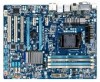
GA-H67A-UD3H-B3 Motherboard Layout KB_USB CPU_FAN ATX_12V_2X4 VGA_DVI LGA1155 PHASE LED DP_HDMI_SPDIF PWR_FAN ESATA_1394_USB USB30_LAN Renesas D720200 AUDIO PCIEX1_1 F_AUDIO Realtek RTL8111E PCIEX16 PCIEX1_2 CODEC PCIEX4 SPDIF_O PCI1 iTE PCI2 IT8728 PCI3 GA-H67A-UD3H-B3 BAT CLR_CMOS iTE IT8892 Bridge T.I. TSB43AB23 ATX DDR3_1 DDR3_2 DDR3_3 DDR3_4 Intel® H67 B_BIOS M_BIOS SYS_FAN2 SATA2_2 SATA2_3 SATA3_0 SATA2_4 SATA3_1 F_PANEL COMA SYS_FAN1 F_1394_1 F_USB4 F_USB2 F_1394_2 F_USB5 F_USB3 F_USB1 - 7 -
GA-H67A-UD3H-B3 Motherboard Layout KB_USB CPU_FAN ATX_12V_2X4 VGA_DVI LGA1155 PHASE LED DP_HDMI_SPDIF PWR_FAN ESATA_1394_USB USB30_LAN Renesas D720200 AUDIO PCIEX1_1 F_AUDIO Realtek RTL8111E PCIEX16 PCIEX1_2 CODEC PCIEX4 SPDIF_O PCI1 iTE PCI2 IT8728 PCI3 GA-H67A-UD3H-B3 BAT CLR_CMOS iTE IT8892 Bridge T.I. TSB43AB23 ATX DDR3_1 DDR3_2 DDR3_3 DDR3_4 Intel® H67 B_BIOS M_BIOS SYS_FAN2 SATA2_2 SATA2_3 SATA3_0 SATA2_4 SATA3_1 F_PANEL COMA SYS_FAN1 F_1394_1 F_USB4 F_USB2 F_1394_2 F_USB5 F_USB3 F_USB1 - 7 -

Manual
Page 8
GA-H67A-UD3H-B3 Motherboard Block Diagram 1 PCI Express x16 PCIe CLK (100 MHz) LGA1155 CPU CPU CLK+/- (100 MHz) DDR3 1333/1066/800 MHz Dual Channel Memory PCI Express ...
GA-H67A-UD3H-B3 Motherboard Block Diagram 1 PCI Express x16 PCIe CLK (100 MHz) LGA1155 CPU CPU CLK+/- (100 MHz) DDR3 1333/1066/800 MHz Dual Channel Memory PCI Express ...

Manual
Page 9
...computer system on an uneven surface. • Do not place the computer system in a high-temperature environment. • Turning on the motherboard, make sure the power supply voltage has been set according to the use of electrostatic discharge (ESD). If you are connected tightly and securely.... • When handling the motherboard, avoid touching any installation steps or have a problem related to the local voltage standard. • Before using the product, please verify ...
...computer system on an uneven surface. • Do not place the computer system in a high-temperature environment. • Turning on the motherboard, make sure the power supply voltage has been set according to the use of electrostatic discharge (ESD). If you are connected tightly and securely.... • When handling the motherboard, avoid touching any installation steps or have a problem related to the local voltage standard. • Before using the product, please verify ...

Manual
Page 12
... Support for Xpress Install Support for Xpress Recovery2 Support for Microsoft® Windows® 7/Vista/XP Form Factor w ATX Form Factor; 30.5cm x 24.4cm * GIGABYTE reserves the right to make any changes to the product specifications and product-related information without prior notice. Hardware Installation - 12 - Support for Dynamic Energy... Charge Support for Cloud OC Support for Q-Share Norton Internet Security (OEM version) Operating System w Support for EasyTune * Available functions in EasyTune may differ by motherboard model.
... Support for Xpress Install Support for Xpress Recovery2 Support for Microsoft® Windows® 7/Vista/XP Form Factor w ATX Form Factor; 30.5cm x 24.4cm * GIGABYTE reserves the right to make any changes to the product specifications and product-related information without prior notice. Hardware Installation - 12 - Support for Dynamic Energy... Charge Support for Cloud OC Support for Q-Share Norton Internet Security (OEM version) Operating System w Support for EasyTune * Available functions in EasyTune may differ by motherboard model.

Manual
Page 13
... One Corner of the CPU. • Do not turn on the computer if the CPU cooler is not recommended that the motherboard supports the CPU. (Go to GIGABYTE's website for the latest CPU support list.) • Always turn off the computer and unplug the power cord from the power...according to your hardware specifications including the CPU, graphics card, memory, hard drive, etc. 1-3-1 Installing the CPU A. Locate the alignment keys on the motherboard CPU socket and the notches on the CPU - 13 - 1-3 Installing the CPU and CPU Cooler Read the following guidelines before installing the CPU to...
... One Corner of the CPU. • Do not turn on the computer if the CPU cooler is not recommended that the motherboard supports the CPU. (Go to GIGABYTE's website for the latest CPU support list.) • Always turn off the computer and unplug the power cord from the power...according to your hardware specifications including the CPU, graphics card, memory, hard drive, etc. 1-3-1 Installing the CPU A. Locate the alignment keys on the motherboard CPU socket and the notches on the CPU - 13 - 1-3 Installing the CPU and CPU Cooler Read the following guidelines before installing the CPU to...

Manual
Page 14
... completely lift the CPU socket lever and the metal load plate will be lifted as shown. Step 5: Push the CPU socket lever back into the motherboard CPU socket. Hold your thumb and index fingers. Step 1: Gently press the CPU socket lever handle down on the rear grip of the load plate...
... completely lift the CPU socket lever and the metal load plate will be lifted as shown. Step 5: Push the CPU socket lever back into the motherboard CPU socket. Hold your thumb and index fingers. Step 1: Gently press the CPU socket lever handle down on the rear grip of the load plate...

Manual
Page 15
1-3-2 Installing the CPU Cooler Follow the steps below to correctly install the CPU cooler on the motherboard. (The following procedure uses Intel® boxed cooler as the picture above shows, the installation is complete. Check that the Male and Female push pins ...are joined closely. (Refer to the CPU fan header (CPU_FAN) on the motherboard. Push down each push pin. Step 4: You should hear a "click" when pushing down on installing the cooler.) Step 5: After the installation, check the back of...
1-3-2 Installing the CPU Cooler Follow the steps below to correctly install the CPU cooler on the motherboard. (The following procedure uses Intel® boxed cooler as the picture above shows, the installation is complete. Check that the Male and Female push pins ...are joined closely. (Refer to the CPU fan header (CPU_FAN) on the motherboard. Push down each push pin. Step 4: You should hear a "click" when pushing down on installing the cooler.) Step 5: After the installation, check the back of...

Manual
Page 16
...in only one DDR3 memory module is recommended that the motherboard supports the memory. After the memory is recommended that memory of the same capacity, brand, speed, and chips be used . (Go to GIGABYTE's website for optimum performance. Enabling Dual Channel memory mode...power cord from the power outlet before installing the memory to insert the memory, switch the direction. 1-4-1 Dual Channel Memory Configuration This motherboard provides four DDR3 memory sockets and supports Dual Channel Technology. 1-4 Installing the Memory Read the following : Channel 0: DDR3_1, DDR3_2 Channel...
...in only one DDR3 memory module is recommended that the motherboard supports the memory. After the memory is recommended that memory of the same capacity, brand, speed, and chips be used . (Go to GIGABYTE's website for optimum performance. Enabling Dual Channel memory mode...power cord from the power outlet before installing the memory to insert the memory, switch the direction. 1-4-1 Dual Channel Memory Configuration This motherboard provides four DDR3 memory sockets and supports Dual Channel Technology. 1-4 Installing the Memory Read the following : Channel 0: DDR3_1, DDR3_2 Channel...

Manual
Page 17
..., make sure to turn off the computer and unplug the power cord from the power outlet to prevent damage to install DDR3 DIMMs on this motherboard.
..., make sure to turn off the computer and unplug the power cord from the power outlet to prevent damage to install DDR3 DIMMs on this motherboard.

Manual
Page 18
... turn off the computer and unplug the power cord from the power outlet before you begin to install an expansion card: • Make sure the motherboard supports the expansion card. Locate an expansion slot that came with the slot, and press down on your card. Secure the card's metal bracket to...
... turn off the computer and unplug the power cord from the power outlet before you begin to install an expansion card: • Make sure the motherboard supports the expansion card. Locate an expansion slot that came with the slot, and press down on your card. Secure the card's metal bracket to...

Manual
Page 20
... the DisplayPort device, make sure the default device for sound playback is compatible with SATA 1.5Gb/s standard. Use this port for the Onboard Graphics: This motherboard provides four video output ports: D-Sub, DVI-D, HDMI, and DisplayPort. Hardware Installation - 20 - RJ-45 LAN Port The Gigabit Ethernet LAN port provides Internet connection...
... the DisplayPort device, make sure the default device for sound playback is compatible with SATA 1.5Gb/s standard. Use this port for the Onboard Graphics: This motherboard provides four video output ports: D-Sub, DVI-D, HDMI, and DisplayPort. Hardware Installation - 20 - RJ-45 LAN Port The Gigabit Ethernet LAN port provides Internet connection...

Manual
Page 21
... 2/4/5.1/7.1-Channel Audio." • When removing the cable connected to a back panel connector, first remove the cable from your device and then remove it from the motherboard. • When removing the cable, pull it side to side to the instructions on setting up a 2/4/5.1/7.1-channel audio configuration in a 4/5.1/7.1-channel audio configuration. Hardware Installation...
... 2/4/5.1/7.1-Channel Audio." • When removing the cable connected to a back panel connector, first remove the cable from your device and then remove it from the motherboard. • When removing the cable, pull it side to side to the instructions on setting up a 2/4/5.1/7.1-channel audio configuration in a 4/5.1/7.1-channel audio configuration. Hardware Installation...

Manual
Page 22
..., make sure your devices are compliant with the connectors you wish to connect. • Before installing the devices, be sure to the connector on the motherboard.
..., make sure your devices are compliant with the connectors you wish to connect. • Before installing the devices, be sure to the connector on the motherboard.

Manual
Page 23
... the power supply is not connected, the computer will not start. If the 12V power connector is turned off and all the components on the motherboard. To meet expansion requirements, it is used (500W or greater).
... the power supply is not connected, the computer will not start. If the 12V power connector is turned off and all the components on the motherboard. To meet expansion requirements, it is used (500W or greater).

Manual
Page 24
...in the correct orientation (the black connector wire is the ground wire). When connecting a fan cable, be installed inside the chassis. The motherboard supports CPU fan speed control, which requires the use of a CPU fan with fan speed control design. Definition 1 1 GND CPU_FAN ...8226; These fan headers are not configuration jumper blocks. Most fan headers possess a foolproof insertion design. 3/4/5) CPU_FAN/SYS_FAN1/SYS_FAN2/PWR_FAN (Fan Headers) The motherboard has a 4-pin CPU fan header (CPU_FAN), a 4-pin (SYS_FAN1) and a 3-pin (SYS_ FAN2) system fans, and a 3-pin power fan....
...in the correct orientation (the black connector wire is the ground wire). When connecting a fan cable, be installed inside the chassis. The motherboard supports CPU fan speed control, which requires the use of a CPU fan with fan speed control design. Definition 1 1 GND CPU_FAN ...8226; These fan headers are not configuration jumper blocks. Most fan headers possess a foolproof insertion design. 3/4/5) CPU_FAN/SYS_FAN1/SYS_FAN2/PWR_FAN (Fan Headers) The motherboard has a 4-pin CPU fan header (CPU_FAN), a 4-pin (SYS_FAN1) and a 3-pin (SYS_ FAN2) system fans, and a 3-pin power fan....


