
Manual
Page 2
Motherboard GA-H61M-S2H Jul. 15, 2011 Motherboard GA-H61M-S2H Jul. 15, 2011
Motherboard GA-H61M-S2H Jul. 15, 2011 Motherboard GA-H61M-S2H Jul. 15, 2011

Manual
Page 3
... this product, carefully read the User's Manual. For product-related information, check on our website at: http://www.gigabyte.com Identifying Your Motherboard Revision The revision number on your motherboard revision before updating motherboard BIOS, drivers, or when looking for technical information. Changes to their respective owners. For example, "REV: 1.0" means the revision...
... this product, carefully read the User's Manual. For product-related information, check on our website at: http://www.gigabyte.com Identifying Your Motherboard Revision The revision number on your motherboard revision before updating motherboard BIOS, drivers, or when looking for technical information. Changes to their respective owners. For example, "REV: 1.0" means the revision...
Manual
Page 4
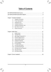
Table of Contents GA-H61M-S2H Motherboard Layout 5 GA-H61M-S2H Motherboard Block Diagram 6 Chapter 1 Hardware Installation 7 1-1 Installation Precautions 7 1-2 Product Specifications 8 1-3 Installing the CPU 10 1-4 Installing the Memory 11 1-5 Installing an Expansion Card 11 1-6 Back Panel Connectors ...
Table of Contents GA-H61M-S2H Motherboard Layout 5 GA-H61M-S2H Motherboard Block Diagram 6 Chapter 1 Hardware Installation 7 1-1 Installation Precautions 7 1-2 Product Specifications 8 1-3 Installing the CPU 10 1-4 Installing the Memory 11 1-5 Installing an Expansion Card 11 1-6 Back Panel Connectors ...

Manual
Page 5
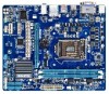
GA-H61M-S2H Motherboard Layout KB_MS ATX_12V LGA1155 VGA_DVI HDMI SYS_FAN R_USB USB_LAN CPU_FAN Atheros AUDIO 8151 BAT PCIEX16 PCI1 GA-H61M-S2H iTE IT8728 CODEC PCIEX1_1 PCIEX1_2 PCIe to PCI Bridge DDR3_1 DDR3_2 M_BIOS B_BIOS ATX Intel® H61 CLR_CMOS F_AUDIO COMA F_USB2 F_USB1 F_PANEL SATA2_3 SATA2_1 SATA2_2 SATA2_0 Box Contents GA-H61M-S2H motherboard Motherboard driver disk User's Manual Two SATA cables I/O Shield * The box contents above are for reference only and the actual items shall depend on the product package you obtain. - 5 -
GA-H61M-S2H Motherboard Layout KB_MS ATX_12V LGA1155 VGA_DVI HDMI SYS_FAN R_USB USB_LAN CPU_FAN Atheros AUDIO 8151 BAT PCIEX16 PCI1 GA-H61M-S2H iTE IT8728 CODEC PCIEX1_1 PCIEX1_2 PCIe to PCI Bridge DDR3_1 DDR3_2 M_BIOS B_BIOS ATX Intel® H61 CLR_CMOS F_AUDIO COMA F_USB2 F_USB1 F_PANEL SATA2_3 SATA2_1 SATA2_2 SATA2_0 Box Contents GA-H61M-S2H motherboard Motherboard driver disk User's Manual Two SATA cables I/O Shield * The box contents above are for reference only and the actual items shall depend on the product package you obtain. - 5 -

Manual
Page 6
GA-H61M-S2H Motherboard Block Diagram 1 PCI Express x16 CPU CLK+/- (100 MHz) LGA1155 CPU DDR3 1333/1066/800 MHz Dual Channel Memory PCIe CLK (100 MHz) x16 PCI Express Bus DMI 2.0 FDI D-Sub DVI-D HDMI LAN RJ45 Atheros 8151 x1 PCI Express Bus x1 x1 PCIe CLK (100 MHz) PCIe to PCI Bridge PCI Bus 2 PCI Express x1 Intel® H61 Dual BIOS 4 SATA 3Gb/s 8 USB 2.0/1.1 LPC Bus iTE IT8728 CODEC COM Port PS/2 KB/Mouse MIC (Center/Subwoofer Speaker Out) Line Out (Front Speaker Out) Line In (Rear Speaker Out) - 6 -
GA-H61M-S2H Motherboard Block Diagram 1 PCI Express x16 CPU CLK+/- (100 MHz) LGA1155 CPU DDR3 1333/1066/800 MHz Dual Channel Memory PCIe CLK (100 MHz) x16 PCI Express Bus DMI 2.0 FDI D-Sub DVI-D HDMI LAN RJ45 Atheros 8151 x1 PCI Express Bus x1 x1 PCIe CLK (100 MHz) PCIe to PCI Bridge PCI Bus 2 PCI Express x1 Intel® H61 Dual BIOS 4 SATA 3Gb/s 8 USB 2.0/1.1 LPC Bus iTE IT8728 CODEC COM Port PS/2 KB/Mouse MIC (Center/Subwoofer Speaker Out) Line Out (Front Speaker Out) Line In (Rear Speaker Out) - 6 -

Manual
Page 7
...installation process can become damaged as a result of the product, please consult a certified computer technician. - 7 - ponents such as a motherboard, CPU or memory. These stickers are required for warranty validation. •• Always remove the AC power by your hardware components are ... the product, please verify that all cables and power connectors of your dealer. Chapter 1 Hardware Installation 1-1 Installation Precautions The motherboard contains numerous delicate electronic circuits and components which can lead to damage to system components as well as physical harm to the ...
...installation process can become damaged as a result of the product, please consult a certified computer technician. - 7 - ponents such as a motherboard, CPU or memory. These stickers are required for warranty validation. •• Always remove the AC power by your hardware components are ... the product, please verify that all cables and power connectors of your dealer. Chapter 1 Hardware Installation 1-1 Installation Precautions The motherboard contains numerous delicate electronic circuits and components which can lead to damage to system components as well as physical harm to the ...

Manual
Page 9
... Center ŠŠ Support for Xpress Install ŠŠ Support for Xpress Recovery2 ŠŠ Support for EasyTune * Available functions in EasyTune may differ by motherboard model. ŠŠ Support for Smart 6™ ŠŠ Support for Auto Green ŠŠ Support for 3TB+ Unlock ŠŠ Support for Cloud OC...
... Center ŠŠ Support for Xpress Install ŠŠ Support for Xpress Recovery2 ŠŠ Support for EasyTune * Available functions in EasyTune may differ by motherboard model. ŠŠ Support for Smart 6™ ŠŠ Support for Auto Green ŠŠ Support for 3TB+ Unlock ŠŠ Support for Cloud OC...

Manual
Page 10
...CPU. If you may occur. •• Set the CPU host frequency in accordance with the CPU specifications. Locate the alignment keys on the motherboard CPU socket and the notches on the CPU - 10 - It is not installed, otherwise overheating and dam- The CPU cannot be set the...for the latest CPU support list.) •• Always turn on the computer if the CPU cooler is not recommended that the motherboard supports the CPU. (Go to GIGABYTE's website for the peripherals. 1-3 Installing the CPU Read the following guidelines before you begin to install the CPU: ••...
...CPU. If you may occur. •• Set the CPU host frequency in accordance with the CPU specifications. Locate the alignment keys on the motherboard CPU socket and the notches on the CPU - 10 - It is not installed, otherwise overheating and dam- The CPU cannot be set the...for the latest CPU support list.) •• Always turn on the computer if the CPU cooler is not recommended that the motherboard supports the CPU. (Go to GIGABYTE's website for the peripherals. 1-3 Installing the CPU Read the following guidelines before you begin to install the CPU: ••...

Manual
Page 11
... installing the memory to prevent hardware damage. •• Memory modules have a foolproof design. Dual Channel Memory Configuration This motherboard provides two DDR3 memory sockets and supports Dual Channel Technology. The two DDR3 memory sockets are unable to prevent hardware damage. ...mode will automatically detect the specifications and capacity of the memory. DDR3_1 DDR3_2 A memory module can be used. (Go to GIGABYTE's website for optimum performance. 1-5 Installing an Expansion Card Read the following guidelines before installing the memory in only one memory socket...
... installing the memory to prevent hardware damage. •• Memory modules have a foolproof design. Dual Channel Memory Configuration This motherboard provides two DDR3 memory sockets and supports Dual Channel Technology. The two DDR3 memory sockets are unable to prevent hardware damage. ...mode will automatically detect the specifications and capacity of the memory. DDR3_1 DDR3_2 A memory module can be used. (Go to GIGABYTE's website for optimum performance. 1-5 Installing an Expansion Card Read the following guidelines before installing the memory in only one memory socket...

Manual
Page 13
...; When removing the cable connected to this jack. Use this audio jack for a headphone or 2-channel speaker. Do not rock it straight out from the motherboard. •• When removing the cable, pull it side to side to 1 Gbps data rate.
...; When removing the cable connected to this jack. Use this audio jack for a headphone or 2-channel speaker. Do not rock it straight out from the motherboard. •• When removing the cable, pull it side to side to 1 Gbps data rate.

Manual
Page 14
... 13 11 79 4 2 5 8 10 6 1) ATX_12V 2) ATX 3) CPU_FAN 4) SYS_FAN 5) SATA2_0/1/2/3 6) F_PANEL 7) F_AUDIO 8) F_USB1/2 9) COMA 10) CLR_CMOS 11) BAT Read the following guidelines before turning on the motherboard. - 14 - Unplug the power cord from the power outlet to prevent damage to the devices. •• After installing the device and before connecting external...
... 13 11 79 4 2 5 8 10 6 1) ATX_12V 2) ATX 3) CPU_FAN 4) SYS_FAN 5) SATA2_0/1/2/3 6) F_PANEL 7) F_AUDIO 8) F_USB1/2 9) COMA 10) CLR_CMOS 11) BAT Read the following guidelines before turning on the motherboard. - 14 - Unplug the power cord from the power outlet to prevent damage to the devices. •• After installing the device and before connecting external...

Manual
Page 15
Connect the power supply cable to the CPU. If a power supply is turned off and all the components on the motherboard. The power connector possesses a foolproof design. If the 12V power connector is recommended that a power supply that does not provide the required power, the result ...
Connect the power supply cable to the CPU. If a power supply is turned off and all the components on the motherboard. The power connector possesses a foolproof design. If the 12V power connector is recommended that a power supply that does not provide the required power, the result ...

Manual
Page 16
The motherboard supports CPU fan speed control, which requires the use of the SATA cable to the CPU or the system may result in the correct orientation (... PORT PORT •• Be sure to connect fan cables to the fan headers to prevent your SATA hard drive. 3/4) CPU_FAN/SYS_FAN (Fan Headers) The motherboard has a 4-pin CPU fan header (CPU_FAN), a 4-pin system fan header (SYS_FAN).
The motherboard supports CPU fan speed control, which requires the use of the SATA cable to the CPU or the system may result in the correct orientation (... PORT PORT •• Be sure to connect fan cables to the fan headers to prevent your SATA hard drive. 3/4) CPU_FAN/SYS_FAN (Fan Headers) The motherboard has a 4-pin CPU fan header (CPU_FAN), a 4-pin system fan header (SYS_FAN).

Manual
Page 18
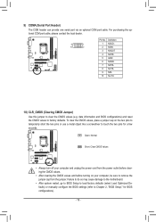
... contact the chassis manufacturer. 8) F_USB1/2 (USB 2.0/1.1 Headers) The headers conform to installing the USB bracket, be present on each wire instead of the motherboard header. Each USB header can provide two USB ports via an optional USB bracket. For information about connecting the front panel audio module that has... sure the wire assignments of the module connector match the pin assignments of a single plug. Incorrect connection between the module connector and the motherboard header will be sure to turn off your chassis front panel audio module to the USB bracket. - 18 -
... contact the chassis manufacturer. 8) F_USB1/2 (USB 2.0/1.1 Headers) The headers conform to installing the USB bracket, be present on each wire instead of the motherboard header. Each USB header can provide two USB ports via an optional USB bracket. For information about connecting the front panel audio module that has... sure the wire assignments of the module connector match the pin assignments of a single plug. Incorrect connection between the module connector and the motherboard header will be sure to turn off your chassis front panel audio module to the USB bracket. - 18 -
Manual
Page 19
..., place a jumper cap on your computer, be sure to remove the jumper cap from the jumper. Failure to do so may cause damage to the motherboard. •• After system restart, go to BIOS Setup to load factory defaults (select Load Optimized Defaults) or manually configure the BIOS settings (refer to...
..., place a jumper cap on your computer, be sure to remove the jumper cap from the jumper. Failure to do so may cause damage to the motherboard. •• After system restart, go to BIOS Setup to load factory defaults (select Load Optimized Defaults) or manually configure the BIOS settings (refer to...

Manual
Page 21
...; It is turned on. A. The LOGO Screen (Default): B. To upgrade the BIOS, use either the GIGABYTE Q-Flash or @BIOS utility. •• Q-Flash allows the user to boot. The POST Screen Motherboard Model BIOS Version Award Modular BIOS v6.00PG Copyright (C) 1984-2011, Award Software, Inc. Chapter 2 BIOS ... system. •• @BIOS is a Windows-based utility that searches and downloads the latest version of the BIOS Setup program. H61M-S2H E5 . . . . : BIOS Setup : XpressRecovery2 : Boot Menu : Qflash 06/28/2011-H61-7A89WG0WC-00 Function Keys Function Keys - 21 -
...; It is turned on. A. The LOGO Screen (Default): B. To upgrade the BIOS, use either the GIGABYTE Q-Flash or @BIOS utility. •• Q-Flash allows the user to boot. The POST Screen Motherboard Model BIOS Version Award Modular BIOS v6.00PG Copyright (C) 1984-2011, Award Software, Inc. Chapter 2 BIOS ... system. •• @BIOS is a Windows-based utility that searches and downloads the latest version of the BIOS Setup program. H61M-S2H E5 . . . . : BIOS Setup : XpressRecovery2 : Boot Menu : Qflash 06/28/2011-H61-7A89WG0WC-00 Function Keys Function Keys - 21 -

Manual
Page 34
...; Move Enter: Select F5: Previous Values +/-/PU/PD: Value F10: Save F6: Fail-Safe Defaults ESC: Exit F1: General Help F7: Optimized Defaults This motherboard incorporates cable diagnostic feature designed to enter the ACPI S1 (Power on Windows 7/Vista operating system only. - 34 - This feature will detect cabling issue and...
...; Move Enter: Select F5: Previous Values +/-/PU/PD: Value F10: Save F6: Fail-Safe Defaults ESC: Exit F1: General Help F7: Optimized Defaults This motherboard incorporates cable diagnostic feature designed to enter the ACPI S1 (Power on Windows 7/Vista operating system only. - 34 - This feature will detect cabling issue and...

Manual
Page 36
...: Exit F1: General Help F7: Optimized Defaults Reset Case Open Status Keeps or clears the record of the chassis intrusion detection device attached to the motherboard CI header. Current System/CPU Temperature Displays current system/CPU temperature. Options are: Disabled (default), 60oC/140oF, 70oC/158oF, 80oC/176oF, 90oC/194oF. - 36 - Current...
...: Exit F1: General Help F7: Optimized Defaults Reset Case Open Status Keeps or clears the record of the chassis intrusion detection device attached to the motherboard CI header. Current System/CPU Temperature Displays current system/CPU temperature. Options are: Disabled (default), 60oC/140oF, 70oC/158oF, 80oC/176oF, 90oC/194oF. - 36 - Current...

Manual
Page 37
... if the CPU/system fan is set for a 4-pin CPU fan that is enabled. Options are the safest and most stable BIOS settings for the motherboard. - 37 - ENxit Setup Exit Without Saving ESC: Quit F8: Q-Flash Select Item F10: Save & Exit Setup Load Fail-Safe Defaults F11: Save CMOS to BIOS...
... if the CPU/system fan is set for a 4-pin CPU fan that is enabled. Options are the safest and most stable BIOS settings for the motherboard. - 37 - ENxit Setup Exit Without Saving ESC: Quit F8: Q-Flash Select Item F10: Save & Exit Setup Load Fail-Safe Defaults F11: Save CMOS to BIOS...

Manual
Page 40
... scan your optical drive. Chapter 3 Drivers Installation • Before installing the drivers, first install the operating system. • After installing the operating system, insert the motherboard driver disk into your system and then list all the recommended drivers. The driver Autorun screen is automatically displayed which looks like that shown in...
... scan your optical drive. Chapter 3 Drivers Installation • Before installing the drivers, first install the operating system. • After installing the operating system, insert the motherboard driver disk into your system and then list all the recommended drivers. The driver Autorun screen is automatically displayed which looks like that shown in...


