
Manual
Page 3
... or download the information on/from the Support&Downloads\Motherboard\Technology Guide page on your motherboard revision before updating motherboard BIOS, drivers, or when looking for technical information. For detailed product information, carefully read the Quick Installation Guide included ...use of this : "REV: X.X." All rights reserved. Example: For product-related information, check on our website at: http://www.gigabyte.com.tw Identifying Your Motherboard Revision The revision number on our website. Disclaimer Information in this manual is 1.0. Copyright © 2010 GIGA...
... or download the information on/from the Support&Downloads\Motherboard\Technology Guide page on your motherboard revision before updating motherboard BIOS, drivers, or when looking for technical information. For detailed product information, carefully read the Quick Installation Guide included ...use of this : "REV: X.X." All rights reserved. Example: For product-related information, check on our website at: http://www.gigabyte.com.tw Identifying Your Motherboard Revision The revision number on our website. Disclaimer Information in this manual is 1.0. Copyright © 2010 GIGA...

Manual
Page 4
Table of Contents Box Contents...6 Optional Items...6 GA-H55N-USB3 Motherboard Layout 7 GA-H55N-USB3 Motherboard Block Diagram 8 Chapter 1 Hardware Installation 9 1-1 Installation Precautions 9 1-2 Product Specifications 10 1-3 Installing the CPU and CPU ... an Expansion Card 18 1-6 Back Panel Connectors 19 1-7 Internal Connectors 22 Chapter 2 BIOS Setup 31 2-1 Startup Screen 32 2-2 The Main Menu 33 2-3 MB Intelligent Tweaker(M.I.T 35 2-4 Standard CMOS Features 44 2-5 Advanced BIOS Features 46 2-6 Integrated Peripherals 48 2-7 Power Management Setup 51 2-8 PC Health Status ...
Table of Contents Box Contents...6 Optional Items...6 GA-H55N-USB3 Motherboard Layout 7 GA-H55N-USB3 Motherboard Block Diagram 8 Chapter 1 Hardware Installation 9 1-1 Installation Precautions 9 1-2 Product Specifications 10 1-3 Installing the CPU and CPU ... an Expansion Card 18 1-6 Back Panel Connectors 19 1-7 Internal Connectors 22 Chapter 2 BIOS Setup 31 2-1 Startup Screen 32 2-2 The Main Menu 33 2-3 MB Intelligent Tweaker(M.I.T 35 2-4 Standard CMOS Features 44 2-5 Advanced BIOS Features 46 2-6 Integrated Peripherals 48 2-7 Power Management Setup 51 2-8 PC Health Status ...

Manual
Page 5
... 58 3-4 Contact...59 3-5 System...59 3-6 Download Center 60 3-7 New Utilities...60 Chapter 4 Unique Features 61 4-1 Xpress Recovery2 61 4-2 BIOS Update Utilities 64 4-2-1 Updating the BIOS with the Q-Flash Utility 64 4-2-2 Updating the BIOS with the @BIOS Utility 67 4-3 EasyTune 6...68 4-4 Dynamic Energy Saver™ 2 69 4-5 Q-Share...71 4-6 Smart 6™...72 4-7 Auto Green...75 Chapter...
... 58 3-4 Contact...59 3-5 System...59 3-6 Download Center 60 3-7 New Utilities...60 Chapter 4 Unique Features 61 4-1 Xpress Recovery2 61 4-2 BIOS Update Utilities 64 4-2-1 Updating the BIOS with the Q-Flash Utility 64 4-2-2 Updating the BIOS with the @BIOS Utility 67 4-3 EasyTune 6...68 4-4 Dynamic Energy Saver™ 2 69 4-5 Q-Share...71 4-6 Smart 6™...72 4-7 Auto Green...75 Chapter...

Manual
Page 7
... CI CPU_FAN VGA_DVI Intel® H55 F_USB2 F_USB1 iTE IT8720 CLR_CMOS ATX_12V HDMI_SPDIF NEC D720200F1 USB_ESATA Realtek RTL8111E (Note 2) USB30_LAN SPDIF_O AUDIO F_AUDIO CODEC LGA1156 GA-H55N-USB3 DDR3_3 PHASE LED DDR3_1 DDR3_2 ATX BAT PCIEX16 M_BIOS B_BIOS (Note 3) (Note 1) Whether this feature is supported depends on the product being received. (Note 2) The...
... CI CPU_FAN VGA_DVI Intel® H55 F_USB2 F_USB1 iTE IT8720 CLR_CMOS ATX_12V HDMI_SPDIF NEC D720200F1 USB_ESATA Realtek RTL8111E (Note 2) USB30_LAN SPDIF_O AUDIO F_AUDIO CODEC LGA1156 GA-H55N-USB3 DDR3_3 PHASE LED DDR3_1 DDR3_2 ATX BAT PCIEX16 M_BIOS B_BIOS (Note 3) (Note 1) Whether this feature is supported depends on the product being received. (Note 2) The...

Manual
Page 8
GA-H55N-USB3 Motherboard Block Diagram 1 PCI Express x16 CPU CLK+/- (133 MHz) PCIe CLK (100 MHz) LGA1156 CPU DDR3 1666 (O.C.)/1333/1066... USB 3.0/2.0 Switch x1 Gen 1 NEC D720200F1 PCI Express Bus Realtek RTL8111E RJ45 LAN Intel® H55 D-Sub DVI-D (Note) HDMI (Note) Dual BIOS 5 SATA 3Gb/s 8 USB 2.0/1.1 CODEC LPC Bus iTE IT8720 PS/2 KB/Mouse Surround Speaker Out Center/Subwoofer Speaker Out Side Speaker Out MIC Line Out...(Note) You can use only one of the onboard digital graphics ports (HDMI and DVI-D) for output when in the BIOS Setup program or when during the POST screens. - 8 -
GA-H55N-USB3 Motherboard Block Diagram 1 PCI Express x16 CPU CLK+/- (133 MHz) PCIe CLK (100 MHz) LGA1156 CPU DDR3 1666 (O.C.)/1333/1066... USB 3.0/2.0 Switch x1 Gen 1 NEC D720200F1 PCI Express Bus Realtek RTL8111E RJ45 LAN Intel® H55 D-Sub DVI-D (Note) HDMI (Note) Dual BIOS 5 SATA 3Gb/s 8 USB 2.0/1.1 CODEC LPC Bus iTE IT8720 PS/2 KB/Mouse Surround Speaker Out Center/Subwoofer Speaker Out Side Speaker Out MIC Line Out...(Note) You can use only one of the onboard digital graphics ports (HDMI and DVI-D) for output when in the BIOS Setup program or when during the POST screens. - 8 -

Manual
Page 11
...-45 port 6 x audio jacks (Center/Subwoofer Speaker Out/Rear Speaker Out/ Side Speaker Out/Line In/Line Out/Microphone) I/O Controller w iTE IT8720 chip Hardware Monitor w w w w BIOS w w w w System voltage detection CPU/System temperature detection CPU/System fan speed detection CPU fan speed control (Note 5) 2 x 64 Mbit flash Use of licensed AWARD...
...-45 port 6 x audio jacks (Center/Subwoofer Speaker Out/Rear Speaker Out/ Side Speaker Out/Line In/Line Out/Microphone) I/O Controller w iTE IT8720 chip Hardware Monitor w w w w BIOS w w w w System voltage detection CPU/System temperature detection CPU/System fan speed detection CPU fan speed control (Note 5) 2 x 64 Mbit flash Use of licensed AWARD...

Manual
Page 12
Unique Features w w w w w w w w w w w w Bundled Software w Support for @BIOS Support for Q-Flash Support for Xpress BIOS Rescue Support for Download Center Support for Xpress Install Support for Xpress Recovery2 Support for EasyTune (Note 6) Support for Dynamic... adapter. (Note 4) You can use only one of the onboard digital graphics ports (HDMI and DVI-D) for output when in the BIOS Setup program or when during the POST screens. (Note 5) Whether the CPU fan speed control function is supported will depend on the ...
Unique Features w w w w w w w w w w w w Bundled Software w Support for @BIOS Support for Q-Flash Support for Xpress BIOS Rescue Support for Download Center Support for Xpress Install Support for Xpress Recovery2 Support for EasyTune (Note 6) Support for Dynamic... adapter. (Note 4) You can use only one of the onboard digital graphics ports (HDMI and DVI-D) for output when in the BIOS Setup program or when during the POST screens. (Note 5) Whether the CPU fan speed control function is supported will depend on the ...

Manual
Page 16
... if only one direction. When enabling Dual Channel mode with two memory modules, it is installed, the BIOS will double the original memory bandwidth. Hardware Installation - 16 - Dual Channel mode cannot be used . (Go to GIGABYTE's website for optimum performance. A memory module can be installed in Dual Channel mode. 1. The two DDR3...
... if only one direction. When enabling Dual Channel mode with two memory modules, it is installed, the BIOS will double the original memory bandwidth. Hardware Installation - 16 - Dual Channel mode cannot be used . (Go to GIGABYTE's website for optimum performance. A memory module can be installed in Dual Channel mode. 1. The two DDR3...

Manual
Page 18
... the driver provided with your card. After installing all expansion cards, replace the chassis cover(s). 6. Hardware Installation - 18 - If necessary, go to BIOS Setup to the chassis back panel with the slot, and press down on the card until it is fully inserted into the slot. 4. Turn on...at the end of the card until it is fully seated in your expansion card(s). 7. Secure the card's metal bracket to make any required BIOS changes for your operating system. Align the card with a screw. 5. PCI Express x16 Slot Follow the steps below to release the card ...
... the driver provided with your card. After installing all expansion cards, replace the chassis cover(s). 6. Hardware Installation - 18 - If necessary, go to BIOS Setup to the chassis back panel with the slot, and press down on the card until it is fully inserted into the slot. 4. Turn on...at the end of the card until it is fully seated in your expansion card(s). 7. Secure the card's metal bracket to make any required BIOS changes for your operating system. Align the card with a screw. 5. PCI Express x16 Slot Follow the steps below to release the card ...

Manual
Page 20
... HDMI ports, you must install an Intel CPU with SATA 1.5Gb/s standard. Use this audio jack to the USB 2.0/1.1 specification. Hardware Installation - 20 - Combination POST/BIOS Windows DVI-D + D-Sub Yes Yes DVI-D + HDMI No Yes HDMI + D-Sub Yes Yes eSATA 3Gb/s Port The eSATA 3Gb/s port conforms to SATA 3Gb/s standard... shows the supported/unsupported dual display configurations for the onboard graphics ports in a 7.1-channel audio configuration. Line In Jack (Blue) The default line in the BIOS Setup program or when during the POST screens.
... HDMI ports, you must install an Intel CPU with SATA 1.5Gb/s standard. Use this audio jack to the USB 2.0/1.1 specification. Hardware Installation - 20 - Combination POST/BIOS Windows DVI-D + D-Sub Yes Yes DVI-D + HDMI No Yes HDMI + D-Sub Yes Yes eSATA 3Gb/s Port The eSATA 3Gb/s port conforms to SATA 3Gb/s standard... shows the supported/unsupported dual display configurations for the onboard graphics ports in a 7.1-channel audio configuration. Line In Jack (Blue) The default line in the BIOS Setup program or when during the POST screens.

Manual
Page 25
...- The LED is on when the hard drive is on the chassis front panel. When connecting your system using the power switch (refer to Chapter 2, "BIOS Setup," "Power Management Setup," for more information). • HD (Hard Drive Activity LED, Blue) Connects to the hard drive activity LED on the chassis front...
...- The LED is on when the hard drive is on the chassis front panel. When connecting your system using the power switch (refer to Chapter 2, "BIOS Setup," "Power Management Setup," for more information). • HD (Hard Drive Activity LED, Blue) Connects to the hard drive activity LED on the chassis front...

Manual
Page 28
...turning on the two pins to temporarily short the two pins or use a metal object like a screwdriver to keep the values (such as BIOS configurations, date, and time information) in the power cord and restart your computer. • Always turn off . self or uncertain about ...You may cause damage to the motherboard. • After system restart, go to BIOS Setup to load factory defaults (select Load Optimized Defaults) or manually configure the BIOS settings (refer to Chapter 2, "BIOS Setup," for BIOS configurations). 12) BAT (Battery) The battery provides power to touch the two pins ...
...turning on the two pins to temporarily short the two pins or use a metal object like a screwdriver to keep the values (such as BIOS configurations, date, and time information) in the power cord and restart your computer. • Always turn off . self or uncertain about ...You may cause damage to the motherboard. • After system restart, go to BIOS Setup to load factory defaults (select Load Optimized Defaults) or manually configure the BIOS settings (refer to Chapter 2, "BIOS Setup," for BIOS configurations). 12) BAT (Battery) The battery provides power to touch the two pins ...

Manual
Page 31
... system's failure to activate certain system features. Chapter 2 BIOS Setup BIOS (Basic Input and Output System) records hardware parameters of the system in the CMOS on . To see more advanced BIOS Setup menu options, you not flash the BIOS. To upgrade the BIOS, use either the GIGABYTE Q-Flash or @BIOS utility. • Q-Flash allows the user to...
... system's failure to activate certain system features. Chapter 2 BIOS Setup BIOS (Basic Input and Output System) records hardware parameters of the system in the CMOS on . To see more advanced BIOS Setup menu options, you not flash the BIOS. To upgrade the BIOS, use either the GIGABYTE Q-Flash or @BIOS utility. • Q-Flash allows the user to...

Manual
Page 32
... Recovery2 to back up arrow key or the down arrow key to select the first boot device, then press to enter BIOS Setup first. Motherboard Model BIOS Version H55N-USB3 E9 . . . . : BIOS Setup : XpressRecovery2 : Boot Menu : Qflash 04/01/2010-H55-7A89TG0VC-00 Function Keys Function Keys SATA Mode Message: ... Q-Flash utility in time. The LOGO Screen (Default) B. Note: This message will display a message during the POST. To show the BIOS POST screen. When the motherboard is found running at IDE MODE!" A. 2-1 Startup Screen The following screens may appear when the computer boots...
... Recovery2 to back up arrow key or the down arrow key to select the first boot device, then press to enter BIOS Setup first. Motherboard Model BIOS Version H55N-USB3 E9 . . . . : BIOS Setup : XpressRecovery2 : Boot Menu : Qflash 04/01/2010-H55-7A89TG0VC-00 Function Keys Function Keys SATA Mode Message: ... Q-Flash utility in time. The LOGO Screen (Default) B. Note: This message will display a message during the POST. To show the BIOS POST screen. When the motherboard is found running at IDE MODE!" A. 2-1 Startup Screen The following screens may appear when the computer boots...

Manual
Page 33
... & Exit Setup Exit Without Saving ESC: Quit F8: Q-Flash Select Item F10: Save & Exit Setup Change CPU's Clock & Voltage F11: Save CMOS to BIOS F12: Load CMOS from BIOS BIOS Setup Program Function Keys Move the selection bar to select an item Execute command or enter the submenu Main Menu: Exit the... screen. Submenu Help While in the Item Help block on the right side of the Main Menu. Help for reference only and may differ by BIOS version. - 33 - 2-2 The Main Menu Once you want in the Main Menu or a submenu, press + to access more advanced options. • When the ...
... & Exit Setup Exit Without Saving ESC: Quit F8: Q-Flash Select Item F10: Save & Exit Setup Change CPU's Clock & Voltage F11: Save CMOS to BIOS F12: Load CMOS from BIOS BIOS Setup Program Function Keys Move the selection bar to select an item Execute command or enter the submenu Main Menu: Exit the... screen. Submenu Help While in the Item Help block on the right side of the Main Menu. Help for reference only and may differ by BIOS version. - 33 - 2-2 The Main Menu Once you want in the Main Menu or a submenu, press + to access more advanced options. • When the ...

Manual
Page 34
... configure the system time and date, hard drive types, and the type of errors that stop the system boot, etc. Advanced BIOS Features Use this menu to configure the device boot order, advanced features available on the CPU, and the primary display adapter. Integrated...configure all peripheral devices, such as IDE, SATA, USB, integrated audio, and integrated LAN, etc. Power Management Setup Use this task.) BIOS Setup - 34 - First enter the profile name (to erase the default profile name, use this menu to see information about autodetected system/CPU temperature,...
... configure the system time and date, hard drive types, and the type of errors that stop the system boot, etc. Advanced BIOS Features Use this menu to configure the device boot order, advanced features available on the CPU, and the primary display adapter. Integrated...configure all peripheral devices, such as IDE, SATA, USB, integrated audio, and integrated LAN, etc. Power Management Setup Use this task.) BIOS Setup - 34 - First enter the profile name (to erase the default profile name, use this menu to see information about autodetected system/CPU temperature,...

Manual
Page 35
BIOS Setup 2-3 MB Intelligent Tweaker(M.I.T.) CMOS Setup Utility-Copyright (C) 1984-2010 Award Software MB Intelligent Tweaker(M.I.T.) } M.I .T. Incorrectly doing overclock/overvoltage may result in damage to ...Frequency Settings } Advanced Memory Settings } Advanced Voltage Settings } Miscellaneous Settings [Press Enter] [Press Enter] [Press Enter] [Press Enter] [Press Enter] Item Help Menu Level BIOS Version BCLK CPU Frequency Memory Frequency Total Memory Size E9 133.37 MHz 3067.78 MHz 1333.75 MHz 1024 MB CPU Temperature PCH Temperature...
BIOS Setup 2-3 MB Intelligent Tweaker(M.I.T.) CMOS Setup Utility-Copyright (C) 1984-2010 Award Software MB Intelligent Tweaker(M.I.T.) } M.I .T. Incorrectly doing overclock/overvoltage may result in damage to ...Frequency Settings } Advanced Memory Settings } Advanced Voltage Settings } Miscellaneous Settings [Press Enter] [Press Enter] [Press Enter] [Press Enter] [Press Enter] Item Help Menu Level BIOS Version BCLK CPU Frequency Memory Frequency Total Memory Size E9 133.37 MHz 3067.78 MHz 1333.75 MHz 1024 MB CPU Temperature PCH Temperature...
Manual
Page 36
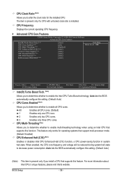
Auto lets the BIOS automatically configure this function. For more information about Intel CPUs' unique features, please visit Intel's website. The item ...Note) Allows you to determine whether to enable multi-threading technology when using an Intel CPU that supports this feature. Auto lets the BIOS automatically configure this setting. (Default: Auto) (Note) This item is installed. When enabled, the CPU core frequency and voltage will...power-saving function in system halt state. This feature only works for the installed CPU. All Enables all CPU cores. BIOS Setup - 36 -
Auto lets the BIOS automatically configure this function. For more information about Intel CPUs' unique features, please visit Intel's website. The item ...Note) Allows you to determine whether to enable multi-threading technology when using an Intel CPU that supports this feature. Auto lets the BIOS automatically configure this setting. (Default: Auto) (Note) This item is installed. When enabled, the CPU core frequency and voltage will...power-saving function in system halt state. This feature only works for the installed CPU. All Enables all CPU cores. BIOS Setup - 36 -
Manual
Page 37
...the CPU core frequency and voltage will be configurable. ting. (Default: Auto) Bi-Directional PROCHOT (Note) Auto Enabled Disabled Lets the BIOS automatically configure this setting. (Default) When the CPU or chipset detects that supports this set the QPI clock ratio. QPI Clock Ratio Allows...you to determine whether to let the CPU enter C3/C6/C7 mode in accordance with unlocked clock ratio is installed. Auto lets the BIOS automatically configure this setting. (Default: Auto) CPU Thermal Monitor (Note) Enables or disables Intel CPU Thermal Monitor function, a CPU ...
...the CPU core frequency and voltage will be configurable. ting. (Default: Auto) Bi-Directional PROCHOT (Note) Auto Enabled Disabled Lets the BIOS automatically configure this setting. (Default) When the CPU or chipset detects that supports this set the QPI clock ratio. QPI Clock Ratio Allows...you to determine whether to let the CPU enter C3/C6/C7 mode in accordance with unlocked clock ratio is installed. Auto lets the BIOS automatically configure this setting. (Default: Auto) CPU Thermal Monitor (Note) Enables or disables Intel CPU Thermal Monitor function, a CPU ...

Manual
Page 38
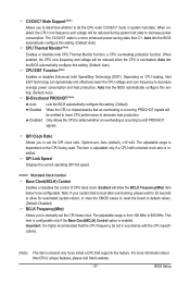
...Note) Uses Profile 2 settings. Options are : 0ps~750ps. (Default: 0ps) (Note) This item appears only if you to enhance memory performance when enabled. BIOS Setup - 38 - The adjustable range is from 400 MHz to 2000 MHz. (Default: Auto) PCI Express Frequency(Mhz) Allows you to the CPU clock.... Extreme Memory Profile (X.M.P.) (Note) Allows the BIOS to read the SPD data on XMP memory module(s) to adjust the amplitude of the memory being used; Options are : 700mV, 800mV, 900mV (default...
...Note) Uses Profile 2 settings. Options are : 0ps~750ps. (Default: 0ps) (Note) This item appears only if you to enhance memory performance when enabled. BIOS Setup - 38 - The adjustable range is from 400 MHz to 2000 MHz. (Default: Auto) PCI Express Frequency(Mhz) Allows you to the CPU clock.... Extreme Memory Profile (X.M.P.) (Note) Allows the BIOS to read the SPD data on XMP memory module(s) to adjust the amplitude of the memory being used; Options are : 700mV, 800mV, 900mV (default...


