Manual
Page 1
GA-H55M-S2 LGA1156 socket motherboard for Intel® Core™ i7 processors/Intel® Core™ i5 processors/Intel® Core™ i3 processors/Intel® Pentium® processors User's Manual Rev. 1301 12ME-H55MS2-1301R
GA-H55M-S2 LGA1156 socket motherboard for Intel® Core™ i7 processors/Intel® Core™ i5 processors/Intel® Core™ i3 processors/Intel® Pentium® processors User's Manual Rev. 1301 12ME-H55MS2-1301R
Manual
Page 2
Motherboard GA-H55M-S2 Jun. 21, 2010 Motherboard GA-H55M-S2 Jun. 21, 2010
Motherboard GA-H55M-S2 Jun. 21, 2010 Motherboard GA-H55M-S2 Jun. 21, 2010
Manual
Page 3
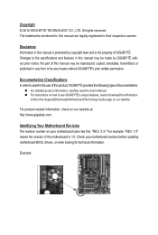
... Documentation Classifications In order to assist in the use GIGABYTE's unique features, read the User's Manual. For instructions on how to use of this product, GIGABYTE provides the following types of the motherboard is the property of this manual may be reproduced,... check on our website at: http://www.gigabyte.com Identifying Your Motherboard Revision The revision number on our website. Check your motherboard looks like this manual may be made by GIGABYTE without GIGABYTE's prior written permission. No part of GIGABYTE. The trademarks mentioned in this : "REV:...
... Documentation Classifications In order to assist in the use GIGABYTE's unique features, read the User's Manual. For instructions on how to use of this product, GIGABYTE provides the following types of the motherboard is the property of this manual may be reproduced,... check on our website at: http://www.gigabyte.com Identifying Your Motherboard Revision The revision number on our website. Check your motherboard looks like this manual may be made by GIGABYTE without GIGABYTE's prior written permission. No part of GIGABYTE. The trademarks mentioned in this : "REV:...
Manual
Page 4
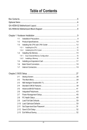
Table of Contents Box Contents...6 Optional Items...6 GA-H55M-S2 Motherboard Layout 7 GA-H55M-S2 Motherboard Block Diagram 8 Chapter 1 Hardware Installation 9 1-1 Installation Precautions 9 1-2 Product Specifications 10 1-3 Installing the CPU and CPU Cooler 12 1-3-1 Installing the CPU 12 1-3-2 Installing the CPU Cooler ...
Table of Contents Box Contents...6 Optional Items...6 GA-H55M-S2 Motherboard Layout 7 GA-H55M-S2 Motherboard Block Diagram 8 Chapter 1 Hardware Installation 9 1-1 Installation Precautions 9 1-2 Product Specifications 10 1-3 Installing the CPU and CPU Cooler 12 1-3-1 Installing the CPU 12 1-3-2 Installing the CPU Cooler ...
Manual
Page 6
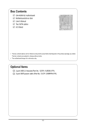
The box contents are for reference only. Optional Items 2-port USB 2.0 bracket (Part No. 12CR1-1UB030-5*R) 2-port SATA power cable (Part No. 12CF1-2SERPW-0*R) - 6 - Box Contents GA-H55M-S2 motherboard Motherboard driver disk User's Manual Two SATA cables I/O Shield • The box contents above are subject to change without notice. • The motherboard image is for reference only and the actual items shall depend on the product package you obtain.
The box contents are for reference only. Optional Items 2-port USB 2.0 bracket (Part No. 12CR1-1UB030-5*R) 2-port SATA power cable (Part No. 12CF1-2SERPW-0*R) - 6 - Box Contents GA-H55M-S2 motherboard Motherboard driver disk User's Manual Two SATA cables I/O Shield • The box contents above are subject to change without notice. • The motherboard image is for reference only and the actual items shall depend on the product package you obtain.
Manual
Page 7
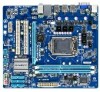
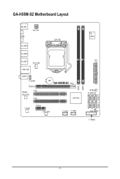
GA-H55M-S2 Motherboard Layout KB_MS VGA ATX_12V R_USB3 LGA1156 R_USB2 R_USB1 CPU_FAN USB_LAN AUDIO F_AUDIO PCIEX16 Realtek PCI1 RTL8111E PCI2 BAT GA-H55M-S2 Intel® H55 CODEC PCIEX1 SYS_FAN F_USB2 F_USB1 iTE IT8720 ATX M_BIOS B_BIOS CLR_CMOS F_PANEL DDR3_1 DDR3_2 SATA2_5 SATA2_2 SATA2_4 SATA2_1 SATA2_3 SATA2_0 - 7 -
GA-H55M-S2 Motherboard Layout KB_MS VGA ATX_12V R_USB3 LGA1156 R_USB2 R_USB1 CPU_FAN USB_LAN AUDIO F_AUDIO PCIEX16 Realtek PCI1 RTL8111E PCI2 BAT GA-H55M-S2 Intel® H55 CODEC PCIEX1 SYS_FAN F_USB2 F_USB1 iTE IT8720 ATX M_BIOS B_BIOS CLR_CMOS F_PANEL DDR3_1 DDR3_2 SATA2_5 SATA2_2 SATA2_4 SATA2_1 SATA2_3 SATA2_0 - 7 -
Manual
Page 8
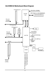
GA-H55M-S2 Motherboard Block Diagram 1 PCI Express x16 LGA1156 CPU CPU CLK+/- (133 MHz) DDR3 1666 (O.C.)/1333/1066/800 MHz Dual Channel Memory PCIe CLK (100 MHz) x16 PCI Express Bus 1 PCI Express x1 LAN PCIe CLK (100 MHz) PCI Express Bus x1 RJ45 Realtek RTL8111E x1 PCI Bus FDI Interface DMI Interface Intel® H55 D-Sub Dual BIOS 6 SATA 3Gb/s 12 USB Ports CODEC LPC Bus iTE IT8720 PS/2 KB/Mouse 2 PCI PCI CLK (33 MHz) MIC (Center/Subwoofer Speakcer Out ) Line Out (Front Speakcer Out ) Line In (Rear Speakcer Out ) - 8 -
GA-H55M-S2 Motherboard Block Diagram 1 PCI Express x16 LGA1156 CPU CPU CLK+/- (133 MHz) DDR3 1666 (O.C.)/1333/1066/800 MHz Dual Channel Memory PCIe CLK (100 MHz) x16 PCI Express Bus 1 PCI Express x1 LAN PCIe CLK (100 MHz) PCI Express Bus x1 RJ45 Realtek RTL8111E x1 PCI Bus FDI Interface DMI Interface Intel® H55 D-Sub Dual BIOS 6 SATA 3Gb/s 12 USB Ports CODEC LPC Bus iTE IT8720 PS/2 KB/Mouse 2 PCI PCI CLK (33 MHz) MIC (Center/Subwoofer Speakcer Out ) Line Out (Front Speakcer Out ) Line In (Rear Speakcer Out ) - 8 -
Manual
Page 9
...computer system on an uneven surface. • Do not place the computer system in a high-temperature environment. • Turning on the motherboard, make sure the power supply voltage has been set according to the local voltage standard. • Before using the product, please verify... warranty validation. • Always remove the AC power by your hardware components are connected tightly and securely. • When handling the motherboard, avoid touching any installation steps or have a problem related to wear an electrostatic discharge (ESD) wrist strap when handling electronic com-...
...computer system on an uneven surface. • Do not place the computer system in a high-temperature environment. • Turning on the motherboard, make sure the power supply voltage has been set according to the local voltage standard. • Before using the product, please verify... warranty validation. • Always remove the AC power by your hardware components are connected tightly and securely. • When handling the motherboard, avoid touching any installation steps or have a problem related to wear an electrostatic discharge (ESD) wrist strap when handling electronic com-...
Manual
Page 11
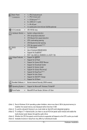
... 4) Whether the CPU fan speed control function is supported will depend on the CPU cooler you install. (Note 5) Available functions in EasyTune may differ by motherboard model. - 11 -
... 4) Whether the CPU fan speed control function is supported will depend on the CPU cooler you install. (Note 5) Available functions in EasyTune may differ by motherboard model. - 11 -
Manual
Page 12
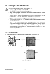
...surface of the CPU. • Do not turn on the computer if the CPU cooler is not recommended that the motherboard supports the CPU. (Go to GIGABYTE's website for the peripherals. It is not installed, otherwise overheating and dam- LGA1156 CPU Socket Alignment Key Alignment Key ...your hardware specifications including the CPU, graphics card, memory, hard drive, etc. 1-3-1 Installing the CPU A. Locate the alignment keys on the motherboard CPU socket and the notches on the CPU Hardware Installation - 12 - The CPU cannot be set the frequency beyond hardware specifications since it ...
...surface of the CPU. • Do not turn on the computer if the CPU cooler is not recommended that the motherboard supports the CPU. (Go to GIGABYTE's website for the peripherals. It is not installed, otherwise overheating and dam- LGA1156 CPU Socket Alignment Key Alignment Key ...your hardware specifications including the CPU, graphics card, memory, hard drive, etc. 1-3-1 Installing the CPU A. Locate the alignment keys on the motherboard CPU socket and the notches on the CPU Hardware Installation - 12 - The CPU cannot be set the frequency beyond hardware specifications since it ...
Manual
Page 13
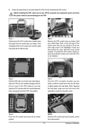
... when the CPU is not installed.) Step 3: Hold the CPU with your thumb and index fingers. Step 5: Push the CPU socket lever back into the motherboard CPU socket. Hardware Installation Hold your thumb to lift up the front edge (next to the "REMOVE" mark) and then remove the cover. (DO NOT...
... when the CPU is not installed.) Step 3: Hold the CPU with your thumb and index fingers. Step 5: Push the CPU socket lever back into the motherboard CPU socket. Hardware Installation Hold your thumb to lift up the front edge (next to the "REMOVE" mark) and then remove the cover. (DO NOT...

Manual
Page 14
... between the CPU cooler and CPU may damage the CPU. Inadequately removing the CPU cooler may adhere to the CPU fan header (CPU_FAN) on the motherboard. Hardware Installation - 14 - Step 4: You should hear a "click" when pushing down on the push pins diagonally. Step 6: Finally, attach the ...the contrary, is to install.) Step 3: Place the cooler atop the CPU, aligning the four push pins through the pin holes on the motherboard. (The following procedure uses Intel® boxed cooler as the picture above shows, the installation is inserted as the example cooler.) Direction of ...
... between the CPU cooler and CPU may damage the CPU. Inadequately removing the CPU cooler may adhere to the CPU fan header (CPU_FAN) on the motherboard. Hardware Installation - 14 - Step 4: You should hear a "click" when pushing down on the push pins diagonally. Step 6: Finally, attach the ...the contrary, is to install.) Step 3: Place the cooler atop the CPU, aligning the four push pins through the pin holes on the motherboard. (The following procedure uses Intel® boxed cooler as the picture above shows, the installation is inserted as the example cooler.) Direction of ...
Manual
Page 15
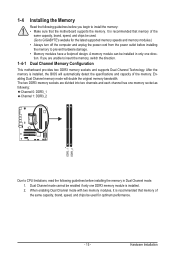
If you begin to install the memory: • Make sure that the motherboard supports the memory. Dual Channel mode cannot be used for the latest supported memory speeds and memory modules.) • Always turn off the ..., brand, speed, and chips be enabled if only one direction. A memory module can be used . (Go to GIGABYTE's website for optimum performance. - 15 - Hardware Installation Dual Channel Memory Configuration This motherboard provides two DDR3 memory sockets and supports Dual Channel Technology. Enabling Dual Channel memory mode will automatically detect the...
If you begin to install the memory: • Make sure that the motherboard supports the memory. Dual Channel mode cannot be used for the latest supported memory speeds and memory modules.) • Always turn off the ..., brand, speed, and chips be enabled if only one direction. A memory module can be used . (Go to GIGABYTE's website for optimum performance. - 15 - Hardware Installation Dual Channel Memory Configuration This motherboard provides two DDR3 memory sockets and supports Dual Channel Technology. Enabling Dual Channel memory mode will automatically detect the...
Manual
Page 16
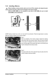
..., make sure to turn off the computer and unplug the power cord from the power outlet to prevent damage to install DDR3 DIMMs on this motherboard. Hardware Installation - 16 -
..., make sure to turn off the computer and unplug the power cord from the power outlet to prevent damage to install DDR3 DIMMs on this motherboard. Hardware Installation - 16 -
Manual
Page 17
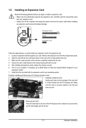
... back panel. 2. PCI Express x16 Slot PCI Slot PCI Express x1 Slot Follow the steps below to install an expansion card: • Make sure the motherboard supports the expansion card. Turn on the card are completely inserted into the PCI Express slot. 1-5 Installing an Expansion Card Read the following guidelines before...
... back panel. 2. PCI Express x16 Slot PCI Slot PCI Express x1 Slot Follow the steps below to install an expansion card: • Make sure the motherboard supports the expansion card. Turn on the card are completely inserted into the PCI Express slot. 1-5 Installing an Expansion Card Read the following guidelines before...
Manual
Page 18
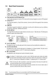
... In Jack (Blue) The default line in jack. Line Out Jack (Green) The default line out jack. Do not rock it straight out from the motherboard. • When removing the cable, pull it side to side to connect a PS/2 keyboard. Hardware Installation - 18 - To configure 7.1-channel audio, you have to use...
... In Jack (Blue) The default line in jack. Line Out Jack (Green) The default line out jack. Do not rock it straight out from the motherboard. • When removing the cable, pull it side to side to connect a PS/2 keyboard. Hardware Installation - 18 - To configure 7.1-channel audio, you have to use...

Manual
Page 19
.... Hardware Installation 1-7 Internal Connectors 1 3 8 6 1) ATX_12V 2) ATX 3) CPU_FAN 4) SYS_FAN 5) SATA2_0/1/2/3/4/5 2 5 10 4 9 7 6) BAT 7) F_PANEL 8) F_AUDIO 9) F_USB1/F_USB2 10) CLR_CMOS Read the following guidelines before turning on the motherboard. - 19 -
.... Hardware Installation 1-7 Internal Connectors 1 3 8 6 1) ATX_12V 2) ATX 3) CPU_FAN 4) SYS_FAN 5) SATA2_0/1/2/3/4/5 2 5 10 4 9 7 6) BAT 7) F_PANEL 8) F_AUDIO 9) F_USB1/F_USB2 10) CLR_CMOS Read the following guidelines before turning on the motherboard. - 19 -

Manual
Page 20
... are properly installed. Connect the power supply cable to the CPU. To meet expansion requirements, it is turned off and all the components on the motherboard. If a power supply is not connected, the computer will not start. The power connector possesses a foolproof design. The 12V power connector mainly supplies power to...
... are properly installed. Connect the power supply cable to the CPU. To meet expansion requirements, it is turned off and all the components on the motherboard. If a power supply is not connected, the computer will not start. The power connector possesses a foolproof design. The 12V power connector mainly supplies power to...
Manual
Page 21
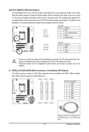
...PORT PORT PORT • Be sure to connect fan cables to the fan headers to connect it is the ground wire). The motherboard supports CPU fan speed control, which requires the use of the SATA cable to SATA 3Gb/s standard and are not configuration jumper blocks...your CPU and system from overheating. Please connect the L-shaped end of a CPU fan with SATA 1.5Gb/s standard. 3/4) CPU_FAN/SYS_FAN (Fan Headers) The motherboard has a 4-pin CPU fan header (CPU_FAN) and a 3-pin system fan header (SYS_FAN). Hardware Installation Each SATA connector supports a single SATA device. ...
...PORT PORT PORT • Be sure to connect fan cables to the fan headers to connect it is the ground wire). The motherboard supports CPU fan speed control, which requires the use of the SATA cable to SATA 3Gb/s standard and are not configuration jumper blocks...your CPU and system from overheating. Please connect the L-shaped end of a CPU fan with SATA 1.5Gb/s standard. 3/4) CPU_FAN/SYS_FAN (Fan Headers) The motherboard has a 4-pin CPU fan header (CPU_FAN) and a 3-pin system fan header (SYS_FAN). Hardware Installation Each SATA connector supports a single SATA device. ...
Manual
Page 24
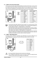
... power cord from the power outlet to prevent damage to installing the USB bracket, be present on each wire instead of the motherboard header. Definition Pin No. For purchasing the optional USB bracket, please contact the local dealer. For information about connecting the front...front panel audio module), refer to activate AC'97 functionality via an optional USB bracket. Incorrect connection between the module connector and the motherboard header will be sure to turn off your chassis front panel audio module to USB 2.0/1.1 specification. 8) F_AUDIO (Front Panel Audio Header...
... power cord from the power outlet to prevent damage to installing the USB bracket, be present on each wire instead of the motherboard header. Definition Pin No. For purchasing the optional USB bracket, please contact the local dealer. For information about connecting the front...front panel audio module), refer to activate AC'97 functionality via an optional USB bracket. Incorrect connection between the module connector and the motherboard header will be sure to turn off your chassis front panel audio module to USB 2.0/1.1 specification. 8) F_AUDIO (Front Panel Audio Header...


