
Manual
Page 3
... is 1.0. For product-related information, check on our website at: http://www.gigabyte.com.tw Identifying Your Motherboard Revision The revision number on our website. Check your motherboard looks like this manual are legally registered to assist in this : "REV: ... Classifications In order to their respective owners. Changes to use GIGABYTE's unique features, read or download the information on/from the Support\Motherboard\Technology Guide page on your motherboard revision before updating motherboard BIOS, drivers, or when looking for technical information. The ...
... is 1.0. For product-related information, check on our website at: http://www.gigabyte.com.tw Identifying Your Motherboard Revision The revision number on our website. Check your motherboard looks like this manual are legally registered to assist in this : "REV: ... Classifications In order to their respective owners. Changes to use GIGABYTE's unique features, read or download the information on/from the Support\Motherboard\Technology Guide page on your motherboard revision before updating motherboard BIOS, drivers, or when looking for technical information. The ...

Manual
Page 4
Table of Contents OptionalItems ...6 Box Contents ...6 GA-GC330UD Motherboard Layout 7 Block Diagram ...8 Chapter 1 Hardware Installation 9 1-1 Installation Precautions 9 1-2 Product Specifications 10 1-3 Installing the Memory 12 1-4 Back Panel Connectors 13 1-5 Internal Connectors 15 Chapter 2 BIOS Setup ...
Table of Contents OptionalItems ...6 Box Contents ...6 GA-GC330UD Motherboard Layout 7 Block Diagram ...8 Chapter 1 Hardware Installation 9 1-1 Installation Precautions 9 1-2 Product Specifications 10 1-3 Installing the Memory 12 1-4 Back Panel Connectors 13 1-5 Internal Connectors 15 Chapter 2 BIOS Setup ...

Manual
Page 6
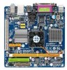
Optional Items 2-port USB 2.0 bracket (Part No. 12CR1-1UB030-5*R) 2-port SATA power cable (Part No. 12CF1-2SERPW-0*R) - 6 - Box Contents GA-GC330UD motherboard Motherboard driver disk User's Manual One IDE cable One SATA 3Gb/s cable I/O Shield • The box contents above are subject to change without notice. • The motherboard image is for reference only and the actual items shall depend on product package you obtain. The box contents are for reference only.
Optional Items 2-port USB 2.0 bracket (Part No. 12CR1-1UB030-5*R) 2-port SATA power cable (Part No. 12CF1-2SERPW-0*R) - 6 - Box Contents GA-GC330UD motherboard Motherboard driver disk User's Manual One IDE cable One SATA 3Gb/s cable I/O Shield • The box contents above are subject to change without notice. • The motherboard image is for reference only and the actual items shall depend on product package you obtain. The box contents are for reference only.

Manual
Page 9
...a result of electrostatic discharge (ESD). Hardware Installation These stickers are connected tightly and securely. • When handling the motherboard, avoid touching any installation steps or have it on top of an antistatic pad or within an electrostatic shielding container. ... power connectors of the product, please consult a certified computer technician. - 9 - Chapter 1 Hardware Installation 1-1 Installation Precautions The motherboard contains numerous delicate electronic circuits and components which can lead to damage to system components as well as physical harm to the user...
...a result of electrostatic discharge (ESD). Hardware Installation These stickers are connected tightly and securely. • When handling the motherboard, avoid touching any installation steps or have it on top of an antistatic pad or within an electrostatic shielding container. ... power connectors of the product, please consult a certified computer technician. - 9 - Chapter 1 Hardware Installation 1-1 Installation Precautions The motherboard contains numerous delicate electronic circuits and components which can lead to damage to system components as well as physical harm to the user...

Manual
Page 10
... Memory 1 x 1.8V DDR2 DIMM socket supporting up to 2 GB of system memory Support for DDR2 667(Note 2)/533 MHz memory module (Go to GIGABYTE's website for the latest memory support list.) Onboard Graphics Integrated in the North Bridge Audio Realtek ALC662 codec High Definition Audio ... header 1 x system fan header 1 x front panel header 1 x front panel audio header 2 x USB 2.0/1.1 headers 1 x chassis intrusion header 1 x power LED header GA-GC330UD Motherboard - 10 -
... Memory 1 x 1.8V DDR2 DIMM socket supporting up to 2 GB of system memory Support for DDR2 667(Note 2)/533 MHz memory module (Go to GIGABYTE's website for the latest memory support list.) Onboard Graphics Integrated in the North Bridge Audio Realtek ALC662 codec High Definition Audio ... header 1 x system fan header 1 x front panel header 1 x front panel audio header 2 x USB 2.0/1.1 headers 1 x chassis intrusion header 1 x power LED header GA-GC330UD Motherboard - 10 -
Manual
Page 11
... these components. (Note 2) The DDR2 667 MHz memory will run at 533 MHz due to a CPU limitation. (Note 3) Available functions in EasyTune may differ by motherboard model. - 11 - Hardware Installation
... these components. (Note 2) The DDR2 667 MHz memory will run at 533 MHz due to a CPU limitation. (Note 3) Available functions in EasyTune may differ by motherboard model. - 11 - Hardware Installation

Manual
Page 12
... place when the memory module is securely inserted. If you begin to install the memory: • Make sure that the motherboard supports the memory. (Go to GIGABYTE's website for the latest memory support list.) • Always turn off the computer and unplug the power cord from the ... module on the socket. A memory module can only fit in the memory socket. Spread the retaining clips at both ends of the memory module. GA-GC330UD Motherboard - 12 - 1-3 Installing the Memory Read the following guidelines before you are unable to insert the memory, switch the direction. • DDR2 DIMMs...
... place when the memory module is securely inserted. If you begin to install the memory: • Make sure that the motherboard supports the memory. (Go to GIGABYTE's website for the latest memory support list.) • Always turn off the computer and unplug the power cord from the ... module on the socket. A memory module can only fit in the memory socket. Spread the retaining clips at both ends of the memory module. GA-GC330UD Motherboard - 12 - 1-3 Installing the Memory Read the following guidelines before you are unable to insert the memory, switch the direction. • DDR2 DIMMs...

Manual
Page 13
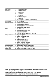
.... Hardware Installation Parallel Port Use the parallel port to a back panel connector, first remove the cable from your device and then remove it from the motherboard. • When removing the cable, pull it side to side to connect devices such as a mouse, modem or other peripherals. D-Sub Port The D-Sub port...
.... Hardware Installation Parallel Port Use the parallel port to a back panel connector, first remove the cable from your device and then remove it from the motherboard. • When removing the cable, pull it side to side to connect devices such as a mouse, modem or other peripherals. D-Sub Port The D-Sub port...

Manual
Page 14
Line Out Jack (Green) The default line out jack. Mic In Jack (Pink) The default Mic in Chapter 5, "Configuring 2/4/5.1-Channel Audio." Microphones must be used to connect front speakers in a 4/5.1-channel audio configuration. This jack can be connected to the instructions on setting up a 2/4/5.1-channel audio configuration in jack. Use this jack. GA-GC330UD Motherboard - 14 - Use this audio jack for a headphone or 2-channel speaker. Refer to this audio jack for line in jack. Line In Jack (Blue) The default line in devices such as an optical drive, walkman, etc.
Line Out Jack (Green) The default line out jack. Mic In Jack (Pink) The default Mic in Chapter 5, "Configuring 2/4/5.1-Channel Audio." Microphones must be used to connect front speakers in a 4/5.1-channel audio configuration. This jack can be connected to the instructions on setting up a 2/4/5.1-channel audio configuration in jack. Use this jack. GA-GC330UD Motherboard - 14 - Use this audio jack for a headphone or 2-channel speaker. Refer to this audio jack for line in jack. Line In Jack (Blue) The default line in devices such as an optical drive, walkman, etc.

Manual
Page 15
..., make sure your devices are compliant with the connectors you wish to connect. • Before installing the devices, be sure to the connector on the motherboard. - 15 - Hardware Installation Unplug the power cord from the power outlet to prevent damage to the devices. • After installing the device and before connecting...
..., make sure your devices are compliant with the connectors you wish to connect. • Before installing the devices, be sure to the connector on the motherboard. - 15 - Hardware Installation Unplug the power cord from the power outlet to prevent damage to the devices. • After installing the device and before connecting...

Manual
Page 16
... 18 19 20 Definition 3.3V -12V GND PS_ON(soft On/Off) GND GND GND -5V +5V +5V GA-GC330UD Motherboard - 16 - If the 12V power connector is turned off and all the components on the motherboard. 1/2) ATX_12V/ATX (2x2 12V Power Connector and 2x12 Main Power Connector) With the use of the power connector...
... 18 19 20 Definition 3.3V -12V GND PS_ON(soft On/Off) GND GND GND -5V +5V +5V GA-GC330UD Motherboard - 16 - If the 12V power connector is turned off and all the components on the motherboard. 1/2) ATX_12V/ATX (2x2 12V Power Connector and 2x12 Main Power Connector) With the use of the power connector...

Manual
Page 17
3/4) CPU_FAN/SYS_FAN (Fan Headers) The motherboard has a 3-pin CPU fan header (CPU_FAN) and a 3-pin system fan header (SYS_FAN). If you wish to connect two IDE devices, remember to set the jumpers ...and the cabling according to the role of a CPU fan with fan speed control design. Most fan headers possess a foolproof insertion design. The motherboard supports CPU fan speed control, which requires the use of the IDE devices (for example, master or slave). (For information about configuring master/slave settings...
3/4) CPU_FAN/SYS_FAN (Fan Headers) The motherboard has a 3-pin CPU fan header (CPU_FAN) and a 3-pin system fan header (SYS_FAN). If you wish to connect two IDE devices, remember to set the jumpers ...and the cabling according to the role of a CPU fan with fan speed control design. Most fan headers possess a foolproof insertion design. The motherboard supports CPU fan speed control, which requires the use of the IDE devices (for example, master or slave). (For information about configuring master/slave settings...

Manual
Page 18
The LED is off (S5). Definition 1 MPD+ 2 MPD- 1 3 MPD- Pin No. Pin No. System Status LED S0 On S1 Blinking S3/S4/S5 Off GA-GC330UD Motherboard - 18 - Each SATA connector supports a single SATA device. Definition 1 1 GND SATA2_1 2 TXP 3 TXN 4 GND 7 5 RXN 1 6 RXP 7 GND SATA2_0 7 Please connect the L-shaped end of the ...
The LED is off (S5). Definition 1 MPD+ 2 MPD- 1 3 MPD- Pin No. Pin No. System Status LED S0 On S1 Blinking S3/S4/S5 Off GA-GC330UD Motherboard - 18 - Each SATA connector supports a single SATA device. Definition 1 1 GND SATA2_1 2 TXP 3 TXN 4 GND 7 5 RXN 1 6 RXP 7 GND SATA2_0 7 Please connect the L-shaped end of the ...

Manual
Page 20
... reading or writing data. • RES (Reset Switch): Connects to the hard drive activity LED on the chassis front panel. You may differ by chassis. GA-GC330UD Motherboard - 20 - Note the positive and negative pins before connecting the cables. The LED is on the chassis front panel. Power Switch Message LED/ Power/ Sleep...
... reading or writing data. • RES (Reset Switch): Connects to the hard drive activity LED on the chassis front panel. You may differ by chassis. GA-GC330UD Motherboard - 20 - Note the positive and negative pins before connecting the cables. The LED is on the chassis front panel. Power Switch Message LED/ Power/ Sleep...

Manual
Page 21
... connections simultaneously. If your chassis front panel audio module to work or even damage it. Hardware Installation Incorrect connection between the module connector and the motherboard header will be present on how to activate AC'97 functioninality via the audio software in Chapter 5, "Configuring 2/4/5.1-Channel Audio." • Audio signals will make... module, refer to the instructions on both of a single plug. Make sure the wire assignments of the module connector match the pin assignments of the motherboard header.
... connections simultaneously. If your chassis front panel audio module to work or even damage it. Hardware Installation Incorrect connection between the module connector and the motherboard header will be present on how to activate AC'97 functioninality via the audio software in Chapter 5, "Configuring 2/4/5.1-Channel Audio." • Audio signals will make... module, refer to the instructions on both of a single plug. Make sure the wire assignments of the module connector match the pin assignments of the motherboard header.

Manual
Page 22
Pin No. 11) F_USB1/F_USB2 (USB Headers) The headers conform to the USB bracket. 12) CI (Chassis Intrusion Header) This motherboard provides a chassis detection feature that detects if the chassis cover has been removed. For purchasing the optional USB bracket, please contact the local dealer. 10 9... cord from the power outlet to prevent damage to USB 2.0/1.1 specification. This function requires a chassis with chassis intrusion detection design. Definition 1 Signal 1 2 GND GA-GC330UD Motherboard - 22 - Each USB header can provide two USB ports via an optional USB bracket.
Pin No. 11) F_USB1/F_USB2 (USB Headers) The headers conform to the USB bracket. 12) CI (Chassis Intrusion Header) This motherboard provides a chassis detection feature that detects if the chassis cover has been removed. For purchasing the optional USB bracket, please contact the local dealer. 10 9... cord from the power outlet to prevent damage to USB 2.0/1.1 specification. This function requires a chassis with chassis intrusion detection design. Definition 1 Signal 1 2 GND GA-GC330UD Motherboard - 22 - Each USB header can provide two USB ports via an optional USB bracket.
Manual
Page 23
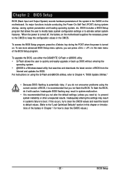
To upgrade the BIOS, use either the GIGABYTE Q-Flash or @BIOS utility. • Q-Flash allows the user to quickly and easily...the battery on using the current version of BIOS, it with caution. When the power is turned on the motherboard. To flash the BIOS, do not encounter problems using the Q-Flash and @BIOS utilities, refer to keep the...of the battery in Chapter 1 for how to prevent system instability or other unexpected results. For instructions on the motherboard supplies the necessary power to the CMOS to Chapter 4, "BIOS Update Utilities." • Because BIOS flashing is ...
To upgrade the BIOS, use either the GIGABYTE Q-Flash or @BIOS utility. • Q-Flash allows the user to quickly and easily...the battery on using the current version of BIOS, it with caution. When the power is turned on the motherboard. To flash the BIOS, do not encounter problems using the Q-Flash and @BIOS utilities, refer to keep the...of the battery in Chapter 1 for how to prevent system instability or other unexpected results. For instructions on the motherboard supplies the necessary power to the CMOS to Chapter 4, "BIOS Update Utilities." • Because BIOS flashing is ...

Manual
Page 24
...based on BIOS Setup settings. Motherboard Model BIOS Version Award Modular BIOS v6.00PG, An Energy Star Ally Copyright (C) 1984-2009, Award Software, Inc. After system restart, the device boot order will directly boot from the device configured in Boot Menu. GA-GC330UD Motherboard - 24 - In Boot ...Menu, use the up hard drive data using the motherboard driver disk, the key can access Boot Menu again to change the first boot device setting as...
...based on BIOS Setup settings. Motherboard Model BIOS Version Award Modular BIOS v6.00PG, An Energy Star Ally Copyright (C) 1984-2009, Award Software, Inc. After system restart, the device boot order will directly boot from the device configured in Boot Menu. GA-GC330UD Motherboard - 24 - In Boot ...Menu, use the up hard drive data using the motherboard driver disk, the key can access Boot Menu again to change the first boot device setting as...

Manual
Page 26
... fan speed, etc. Frequency/Voltage Control Use this menu to the confirmation message will exit BIOS Setup. (Pressing can also carry out this task.) GA-GC330UD Motherboard - 26 - Standard CMOS Features Use this menu to configure the system time and date, hard drive types, and the type of your CPU, memory...
... fan speed, etc. Frequency/Voltage Control Use this menu to the confirmation message will exit BIOS Setup. (Pressing can also carry out this task.) GA-GC330UD Motherboard - 26 - Standard CMOS Features Use this menu to configure the system time and date, hard drive types, and the type of your CPU, memory...

Manual
Page 28
... boot will stop for all other errors. (Default) Memory These fields are read-only and are determined by the BIOS POST. Head Number of cylinders. GA-GC330UD Motherboard - 28 - Cylinder Number of heads. Landing Zone Landing zone. No Errors The system boot will be reserved for any error. Typically, 640 KB will not...
... boot will stop for all other errors. (Default) Memory These fields are read-only and are determined by the BIOS POST. Head Number of cylinders. GA-GC330UD Motherboard - 28 - Cylinder Number of heads. Landing Zone Landing zone. No Errors The system boot will be reserved for any error. Typically, 640 KB will not...


