Manual
Page 4
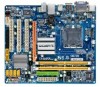
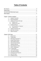
Table of Contents Box Contents...6 Optional Items...6 GA-G41M-ES2H Motherboard Layout 7 Block Diagram...8 Chapter 1 Hardware Installation 9 1-1 Installation Precautions 9 1-2 Product Specifications 10 1-3 Installing the CPU and CPU Cooler 13 1-3-1 Installing the CPU 13 1-3-2 Installing the CPU Cooler 15 1-4 Installing the Memory 16 1-4-1 Dual Channel Memory Configuration 16 1-4-2 Installing a Memory 17 1-5 Installing an Expansion Card 18 1-6 Back Panel Connectors...
Table of Contents Box Contents...6 Optional Items...6 GA-G41M-ES2H Motherboard Layout 7 Block Diagram...8 Chapter 1 Hardware Installation 9 1-1 Installation Precautions 9 1-2 Product Specifications 10 1-3 Installing the CPU and CPU Cooler 13 1-3-1 Installing the CPU 13 1-3-2 Installing the CPU Cooler 15 1-4 Installing the Memory 16 1-4-1 Dual Channel Memory Configuration 16 1-4-2 Installing a Memory 17 1-5 Installing an Expansion Card 18 1-6 Back Panel Connectors...
Manual
Page 8
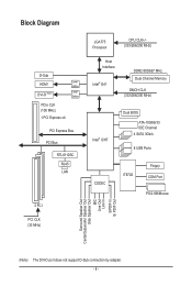
... CLK (100 MHz) 1 PCI Express x4 Level Shifter Level Shifter PCI Express Bus PCI Bus RTL8110SC RJ45 LAN 3 PCI PCI CLK (33 MHz) LGA775 Processor CPU CLK+/(333/266/200 MHz) Host Interface Intel® G41 DDR2 800/667 MHz Dual Channel Memory GMCH CLK (333/266/200 MHz) Intel®...
... CLK (100 MHz) 1 PCI Express x4 Level Shifter Level Shifter PCI Express Bus PCI Bus RTL8110SC RJ45 LAN 3 PCI PCI CLK (33 MHz) LGA775 Processor CPU CLK+/(333/266/200 MHz) Host Interface Intel® G41 DDR2 800/667 MHz Dual Channel Memory GMCH CLK (333/266/200 MHz) Intel®...
Manual
Page 9
Hardware Installation ponents such as a motherboard, CPU or memory. If you do not have an ESD wrist strap, keep your hands dry and first touch a metal object to eliminate static electricity. • ...
Hardware Installation ponents such as a motherboard, CPU or memory. If you do not have an ESD wrist strap, keep your hands dry and first touch a metal object to eliminate static electricity. • ...
Manual
Page 10
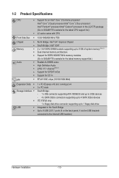
.../ Intel® Pentium® processor/Intel® Celeron® processor in the LGA775 package (Go to GIGABYTE's website for the latest CPU support list.) L2 cache varies with CPU Front Side Bus w 1333/1066/800 MHz FSB Chipset Memory Audio LAN w North Bridge: Intel® ... up to 8 GB of system memory (Note 1) w Dual channel memory architecture w Support for DDR2 800/667 MHz memory modules (Go to GIGABYTE's website for the latest memory support list.) Realtek ALC888B codec High Definition Audio 2/4/5.1/7.1-channel (Note 2) ...
.../ Intel® Pentium® processor/Intel® Celeron® processor in the LGA775 package (Go to GIGABYTE's website for the latest CPU support list.) L2 cache varies with CPU Front Side Bus w 1333/1066/800 MHz FSB Chipset Memory Audio LAN w North Bridge: Intel® ... up to 8 GB of system memory (Note 1) w Dual channel memory architecture w Support for DDR2 800/667 MHz memory modules (Go to GIGABYTE's website for the latest memory support list.) Realtek ALC888B codec High Definition Audio 2/4/5.1/7.1-channel (Note 2) ...
Manual
Page 11
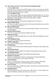
... power connector w 1 x 4-pin ATX 12V power connector w 1 x floppy disk drive connector w 1 x IDE connector w 4 x SATA 3Gb/s connectors w 1 x CPU fan header w 1 x system fan header w 1 x front panel header w 1 x front panel audio header w 1 x CD In connector w 1 x S/PDIF In...IT8720 Hardware Monitor w w w w w w BIOS w w w w System voltage detection CPU/System temperature detection CPU/System fan speed detection CPU overheating warning CPU/System fan fail warning CPU fan speed control (Note 4) 2 x 8 Mbit flash Use of licensed AWARD BIOS Support ...
... power connector w 1 x 4-pin ATX 12V power connector w 1 x floppy disk drive connector w 1 x IDE connector w 4 x SATA 3Gb/s connectors w 1 x CPU fan header w 1 x system fan header w 1 x front panel header w 1 x front panel audio header w 1 x CD In connector w 1 x S/PDIF In...IT8720 Hardware Monitor w w w w w w BIOS w w w w System voltage detection CPU/System temperature detection CPU/System fan speed detection CPU overheating warning CPU/System fan fail warning CPU fan speed control (Note 4) 2 x 8 Mbit flash Use of licensed AWARD BIOS Support ...
Manual
Page 12
... audio feature through the audio driver. (Note 3) The DVI-D port does not support D-Sub connection by adapter. (Note 4) Whether the CPU fan speed control function is supported will depend on the CPU cooler you install. (Note 5) Available functions in EasyTune may differ by motherboard model. (Note 6) Due to the hardware limitation, you...
... audio feature through the audio driver. (Note 3) The DVI-D port does not support D-Sub connection by adapter. (Note 4) Whether the CPU fan speed control function is supported will depend on the CPU cooler you install. (Note 5) Available functions in EasyTune may differ by motherboard model. (Note 6) Due to the hardware limitation, you...
Manual
Page 13
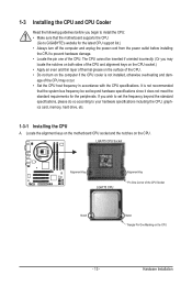
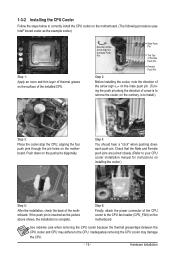
...thermal grease on the computer if the CPU cooler is not recommended that the motherboard supports the CPU. (Go to GIGABYTE's website for the peripherals. Locate the alignment keys on the motherboard CPU socket and the notches on the CPU - 13 - The CPU cannot be inserted if oriented incorrectly.... (Or you begin to install the CPU: • Make sure that...
...thermal grease on the computer if the CPU cooler is not recommended that the motherboard supports the CPU. (Go to GIGABYTE's website for the peripherals. Locate the alignment keys on the motherboard CPU socket and the notches on the CPU - 13 - The CPU cannot be inserted if oriented incorrectly.... (Or you begin to install the CPU: • Make sure that...

Manual
Page 14
... the protective socket cover when the CPU is properly inserted, replace the load plate and push the CPU socket lever back into position. Hardware Installation - 14 - CPU Socket Lever Step 1: Completely raise the CPU socket lever. Step 2: Lift the metal load plate from the CPU socket. (DO NOT touch socket...outlet to prevent damage to correctly install the CPU into the motherboard CPU socket. B. Follow the steps below to the CPU. Align the CPU pin one marking (triangle) with the pin one corner of the CPU socket (or you may align the CPU notches with your thumb and index fingers....
... the protective socket cover when the CPU is properly inserted, replace the load plate and push the CPU socket lever back into position. Hardware Installation - 14 - CPU Socket Lever Step 1: Completely raise the CPU socket lever. Step 2: Lift the metal load plate from the CPU socket. (DO NOT touch socket...outlet to prevent damage to correctly install the CPU into the motherboard CPU socket. B. Follow the steps below to the CPU. Align the CPU pin one marking (triangle) with the pin one corner of the CPU socket (or you may align the CPU notches with your thumb and index fingers....
Manual
Page 15
...the contrary, is complete. Step 4: You should hear a "click" when pushing down on the push pins diagonally. Inadequately removing the CPU cooler may adhere to the CPU. Push down each push pin. If the push pin is inserted as the example cooler.) Step 1: Apply an even and thin layer ...following procedure uses Intel® boxed cooler as the picture above shows, the installation is to install.) Step 3: Place the cooler atop the CPU, aligning the four push pins through the pin holes on installing the cooler.) Step 5: After the installation, check the back of the motherboard.
...the contrary, is complete. Step 4: You should hear a "click" when pushing down on the push pins diagonally. Inadequately removing the CPU cooler may adhere to the CPU. Push down each push pin. If the push pin is inserted as the example cooler.) Step 1: Apply an even and thin layer ...following procedure uses Intel® boxed cooler as the picture above shows, the installation is to install.) Step 3: Place the cooler atop the CPU, aligning the four push pins through the pin holes on installing the cooler.) Step 5: After the installation, check the back of the motherboard.
Manual
Page 20
... up to connect front speakers in Chapter 5, "Configuring 2/4/5.1/7.1-Channel Audio." This jack can only be connected to the recommended system requirements (or better) below. • CPU: Intel Dual-Core processor • Memory: Two 1 GB DDR2 800 memory modules with dual channel mode enabled • Playback software: CyberLink PowerDVD 8.0 or later (Note...
... up to connect front speakers in Chapter 5, "Configuring 2/4/5.1/7.1-Channel Audio." This jack can only be connected to the recommended system requirements (or better) below. • CPU: Intel Dual-Core processor • Memory: Two 1 GB DDR2 800 memory modules with dual channel mode enabled • Playback software: CyberLink PowerDVD 8.0 or later (Note...

Manual
Page 22
The power connector possesses a foolproof design. Connect the power supply cable to the CPU. Do not insert the power supply cables into pins under the protective covers when using a power supply providing a 2x4 12V and a 2x12 power connector, remove ...
The power connector possesses a foolproof design. Connect the power supply cable to the CPU. Do not insert the power supply cables into pins under the protective covers when using a power supply providing a 2x4 12V and a 2x12 power connector, remove ...
Manual
Page 23
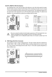
...34 2 - 23 - The pin 1 of the cable is the ground wire). When connecting a fan cable, be sure to connect it is used to prevent your CPU and system from overheating. Overheating may hang. • These fan headers are : 360 KB, 720 KB, 1.2 MB, 1.44 MB, and 2.88 MB. Before connecting... place a jumper cap on the headers. 5) FDD (Floppy Disk Drive Connector) This connector is recommended that a system fan be sure to the CPU or the system may result in the correct orientation (the black connector wire is typically designated by a stripe of the connector and the floppy disk...
...34 2 - 23 - The pin 1 of the cable is the ground wire). When connecting a fan cable, be sure to connect it is used to prevent your CPU and system from overheating. Overheating may hang. • These fan headers are : 360 KB, 720 KB, 1.2 MB, 1.44 MB, and 2.88 MB. Before connecting... place a jumper cap on the headers. 5) FDD (Floppy Disk Drive Connector) This connector is recommended that a system fan be sure to the CPU or the system may result in the correct orientation (the black connector wire is typically designated by a stripe of the connector and the floppy disk...
Manual
Page 33
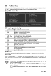
... Optimized Defaults Set Supervisor Password Set User Password Save & Exit Setup Exit Without Saving ESC: Quit F8: Q-Flash Select Item F10: Save & Exit Setup Change CPU's Clock & Voltage F11: Save CMOS to display a help screen. Help for each item is in the Item Help block on the right side of the...
... Optimized Defaults Set Supervisor Password Set User Password Save & Exit Setup Exit Without Saving ESC: Quit F8: Q-Flash Select Item F10: Save & Exit Setup Change CPU's Clock & Voltage F11: Save CMOS to display a help screen. Help for each item is in the Item Help block on the right side of the...
Manual
Page 34
... becomes unstable and you have loaded the BIOS default settings, you can also carry out this menu to see information about autodetected system/CPU temperature, system voltage and fan speed, etc. Load Fail-Safe Defaults Fail-Safe defaults are factory settings for the most stable... stop the system boot, etc. Advanced BIOS Features Use this menu to configure the device boot order, advanced features available on the CPU, and the primary display adapter. Advanced Chipset Features Use this menu to configure advanced features available on the chipset. Integrated...
... becomes unstable and you have loaded the BIOS default settings, you can also carry out this menu to see information about autodetected system/CPU temperature, system voltage and fan speed, etc. Load Fail-Safe Defaults Fail-Safe defaults are factory settings for the most stable... stop the system boot, etc. Advanced BIOS Features Use this menu to configure the device boot order, advanced features available on the CPU, and the primary display adapter. Advanced Chipset Features Use this menu to configure advanced features available on the chipset. Integrated...
Manual
Page 35
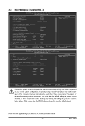
...CMOS Setup Utility-Copyright (C) 1984-2009 Award Software MB Intelligent Tweaker(M.I.T.) Robust Graphics Booster CPU Clock Ratio (Note) Fine CPU Clock Ratio (Note) CPU Frequency [Auto] [12X] [+0.0] 2.40GHz ( 200x12) Item Help Menu Level ******** Clock...Press Enter] Item Help Menu Level ******** Mother Board Voltage Control ******** Voltage Types Normal Current >>> CPU CPU Vcore 1.32500V [Auto] CPU Termination 1.200V [Auto] CPU Reference 0.805V [Auto] >>> DRAM DRAM Voltage 1.800V [Auto] Move Enter: Select F5: Previous Values ...
...CMOS Setup Utility-Copyright (C) 1984-2009 Award Software MB Intelligent Tweaker(M.I.T.) Robust Graphics Booster CPU Clock Ratio (Note) Fine CPU Clock Ratio (Note) CPU Frequency [Auto] [12X] [+0.0] 2.40GHz ( 200x12) Item Help Menu Level ******** Clock...Press Enter] Item Help Menu Level ******** Mother Board Voltage Control ******** Voltage Types Normal Current >>> CPU CPU Vcore 1.32500V [Auto] CPU Termination 1.200V [Auto] CPU Reference 0.805V [Auto] >>> DRAM DRAM Voltage 1.800V [Auto] Move Enter: Select F5: Previous Values ...
Manual
Page 36
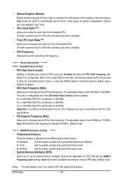
... feature. Note: If your system fails to boot after overclocking, please wait for the installed CPU. For an 800 MHz FSB CPU, set in accordance with the CPU specifications. Standard Lets the system operate at its basic performance level. (Default) Turbo Lets the...Auto) ******** DRAM Performance Control ******** Performance Enhance Allows the system to set the R.G.B. System Memory Multiplier (SPD) Allows you install a CPU that the CPU frequency be configurable. Auto sets memory multiplier according to memory SPD data. (Default: Auto) (Note) This item appears only if you ...
... feature. Note: If your system fails to boot after overclocking, please wait for the installed CPU. For an 800 MHz FSB CPU, set in accordance with the CPU specifications. Standard Lets the system operate at its basic performance level. (Default) Turbo Lets the...Auto) ******** DRAM Performance Control ******** Performance Enhance Allows the system to set the R.G.B. System Memory Multiplier (SPD) Allows you install a CPU that the CPU frequency be configurable. Auto sets memory multiplier according to memory SPD data. (Default: Auto) (Note) This item appears only if you ...
Manual
Page 37
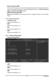
tWR Options are : Auto (default), 3~7. DRAM Timing Selectable (SPD) Manual allows all DRAM timing control items below to the CPU Host Frequency (Mhz) and System Memory Multiplier settings. Options are: Auto (default), Manual. >>>>> Standard Timing Control CAS Latency Time Options are : Auto (default), 1~31. tRAS ...
tWR Options are : Auto (default), 3~7. DRAM Timing Selectable (SPD) Manual allows all DRAM timing control items below to the CPU Host Frequency (Mhz) and System Memory Multiplier settings. Options are: Auto (default), Manual. >>>>> Standard Timing Control CAS Latency Time Options are : Auto (default), 1~31. tRAS ...

Manual
Page 40
CPU PLL The default is Auto. CPU Termination The default is Auto. Clk Driving Pull-Down Level Options are: Auto (default), +8~-7. ******** Mother Board Voltage Control CPU CPU Vcore The default is Auto. BIOS Setup - 40 - Ctrl Driving Pull-Down Level Options are : Auto (default), +8~-7. CPU Reference The default is Auto. >>> DRAM DRAM Voltage The default is Auto. Cmd Driving Pull-Down Level Options are : Auto (default), +8~-7.
CPU PLL The default is Auto. CPU Termination The default is Auto. Clk Driving Pull-Down Level Options are: Auto (default), +8~-7. ******** Mother Board Voltage Control CPU CPU Vcore The default is Auto. BIOS Setup - 40 - Ctrl Driving Pull-Down Level Options are : Auto (default), +8~-7. CPU Reference The default is Auto. >>> DRAM DRAM Voltage The default is Auto. Cmd Driving Pull-Down Level Options are : Auto (default), +8~-7.
Manual
Page 43
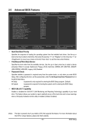
...is required every time the system boots, or only when you install a CPU that supports this feature. BIOS Setup to 3 (Note) No-Execute Memory Protect (Note) CPU Enhanced Halt (C1E) (Note) CPU Thermal Monitor 2(TM2) (Note) CPU EIST Function (Note) Virtualization Technology (Note) Delay For HDD (Secs) ...your system to exit this item, set the password(s) under the Set Supervisor/User Password item in the BIOS Main Menu. Capability CPU Multi-Threading (Note) Limit CPUID Max. First/Second/Third Boot Device Specifies the boot order from the installed hard drives. For ...
...is required every time the system boots, or only when you install a CPU that supports this feature. BIOS Setup to 3 (Note) No-Execute Memory Protect (Note) CPU Enhanced Halt (C1E) (Note) CPU Thermal Monitor 2(TM2) (Note) CPU EIST Function (Note) Virtualization Technology (Note) Delay For HDD (Secs) ...your system to exit this item, set the password(s) under the Set Supervisor/User Password item in the BIOS Main Menu. Capability CPU Multi-Threading (Note) Limit CPUID Max. First/Second/Third Boot Device Specifies the boot order from the installed hard drives. For ...

Manual
Page 44
... buffer overflow attacks when working with its supporting software and system. (Default: Enabled) CPU Enhanced Halt (C1E) (Note) Enables or disables Intel CPU Enhanced Halt (C1E) function, a CPU power-saving function in independent partitions. If the system BIOS is corrupted, it will be... Allows you to set this item to decrease power consumption. (Default: Enabled) CPU Thermal Monitor 2 (TM2) (Note) Enables or disables Intel CPU Thermal Monitor (TM2) function, a CPU overheating protection function. With virtualization, one CPU core. BIOS Setup - 44 - Limit CPUID Max. Set this item to...
... buffer overflow attacks when working with its supporting software and system. (Default: Enabled) CPU Enhanced Halt (C1E) (Note) Enables or disables Intel CPU Enhanced Halt (C1E) function, a CPU power-saving function in independent partitions. If the system BIOS is corrupted, it will be... Allows you to set this item to decrease power consumption. (Default: Enabled) CPU Thermal Monitor 2 (TM2) (Note) Enables or disables Intel CPU Thermal Monitor (TM2) function, a CPU overheating protection function. With virtualization, one CPU core. BIOS Setup - 44 - Limit CPUID Max. Set this item to...


