Manual
Page 3
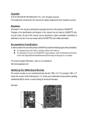
... types of documentations: For detailed product information, carefully read the User's Manual. For instructions on how to use GIGABYTE's unique features, read or download the information on/from the Support&Downloads\Motherboard\Technology Guide page on your motherboard revision before updating motherboard BIOS, drivers, or when looking for technical information...
... types of documentations: For detailed product information, carefully read the User's Manual. For instructions on how to use GIGABYTE's unique features, read or download the information on/from the Support&Downloads\Motherboard\Technology Guide page on your motherboard revision before updating motherboard BIOS, drivers, or when looking for technical information...
Manual
Page 7
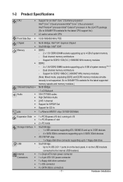
... processor/Intel® Core™ 2 Duo processor/ Intel® Pentium® processor/Intel® Celeron® processor in the LGA775 package (Go to GIGABYTE's website for the latest CPU support list.) L2 cache varies with CPU Front Side Bus w 1333/1066/800 MHz FSB Chipset w w Memory Onboard Graphics Audio ...
... processor/Intel® Core™ 2 Duo processor/ Intel® Pentium® processor/Intel® Celeron® processor in the LGA775 package (Go to GIGABYTE's website for the latest CPU support list.) L2 cache varies with CPU Front Side Bus w 1333/1066/800 MHz FSB Chipset w w Memory Onboard Graphics Audio ...
Manual
Page 8
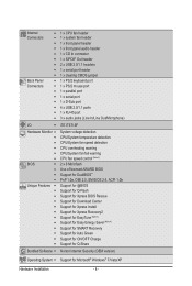
...; PnP 1.0a, DMI 2.0, SM BIOS 2.4, ACPI 1.0b Support for @BIOS Support for Q-Flash Support for Xpress BIOS Rescue Support for Download Center Support for Xpress Install Support for Xpress Recovery2 Support for EasyTune (Note 3) Support for Easy Energy Saver (Note 4) Support for SMART Recovery Support for Auto Green Support for ON/OFF Charge Support for Q-Share Bundled Software w Norton Internet Security (OEM...
...; PnP 1.0a, DMI 2.0, SM BIOS 2.4, ACPI 1.0b Support for @BIOS Support for Q-Flash Support for Xpress BIOS Rescue Support for Download Center Support for Xpress Install Support for Xpress Recovery2 Support for EasyTune (Note 3) Support for Easy Energy Saver (Note 4) Support for SMART Recovery Support for Auto Green Support for ON/OFF Charge Support for Q-Share Bundled Software w Norton Internet Security (OEM...
Manual
Page 9
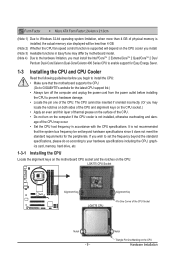
...you must install the Intel®CoreTM 2 Extreme/CoreTM 2 Quad/CoreTM 2 Duo/ Pentium Dual-Core/Celeron Dual-Core/Celeron 400 Series CPU to enable support for Easy Energy Saver. 1-3 Installing the CPU and CPU Cooler Read the following guidelines before installing the CPU to prevent hardware damage. • Locate ...and unplug the power cord from the power outlet before you wish to set beyond the standard specifications, please do so according to GIGABYTE's website for the peripherals. Notch Triangle Pin One Marking on the CPU. It is not installed, otherwise overheating and dam-
...you must install the Intel®CoreTM 2 Extreme/CoreTM 2 Quad/CoreTM 2 Duo/ Pentium Dual-Core/Celeron Dual-Core/Celeron 400 Series CPU to enable support for Easy Energy Saver. 1-3 Installing the CPU and CPU Cooler Read the following guidelines before installing the CPU to prevent hardware damage. • Locate ...and unplug the power cord from the power outlet before you wish to set beyond the standard specifications, please do so according to GIGABYTE's website for the peripherals. Notch Triangle Pin One Marking on the CPU. It is not installed, otherwise overheating and dam-
Manual
Page 10
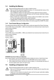
...with two memory modules, it is recommended that memory of the same capacity, brand, speed, and chips be used . (Go to GIGABYTE's website for the latest supported memory speeds and memory modules.) • Always turn off the computer and unplug the power cord from the power outlet before installing ... module can be enabled if only one memory socket as following guidelines before installing the memory to use the memory modules on the memory support list at GIGABYTE's website. 1-4-1 Dual Channel Memory Configuration This motherboard provides two DDR2 and two DDR3 memory sockets and...
...with two memory modules, it is recommended that memory of the same capacity, brand, speed, and chips be used . (Go to GIGABYTE's website for the latest supported memory speeds and memory modules.) • Always turn off the computer and unplug the power cord from the power outlet before installing ... module can be enabled if only one memory socket as following guidelines before installing the memory to use the memory modules on the memory support list at GIGABYTE's website. 1-4-1 Dual Channel Memory Configuration This motherboard provides two DDR2 and two DDR3 memory sockets and...
Manual
Page 11
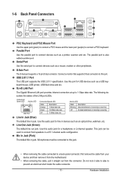
...No data transmission or receiving is also called a printer port. Connect a monitor that supports D-Sub connection to prevent an electrical short inside the cable connector. - 11 - USB 2.0/1.1 Port The USB port supports the USB 2.0/1.1 specification. Line Out Jack (Green) The default line out jack. ...Parallel Port Use the parallel port to connect front speakers in devices such as a printer, scanner and etc. D-Sub Port The D-Sub port supports a 15-pin D-Sub connector. Use this jack. • When removing the cable connected to connect devices such as a USB keyboard/mouse,...
...No data transmission or receiving is also called a printer port. Connect a monitor that supports D-Sub connection to prevent an electrical short inside the cable connector. - 11 - USB 2.0/1.1 Port The USB port supports the USB 2.0/1.1 specification. Line Out Jack (Green) The default line out jack. ...Parallel Port Use the parallel port to connect front speakers in devices such as a printer, scanner and etc. D-Sub Port The D-Sub port supports a 15-pin D-Sub connector. Use this jack. • When removing the cable connected to connect devices such as a USB keyboard/mouse,...
Manual
Page 14
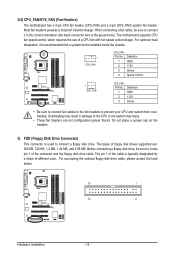
...Do not place a jumper cap on the headers. 5) FDD (Floppy Disk Drive Connector) This connector is the ground wire). The motherboard supports CPU fan speed control, which requires the use of the cable is recommended that a system fan be sure to connect it is typically designated... a stripe of different color. Overheating may result in the correct orientation (the black connector wire is used to locate pin 1 of floppy disk drives supported are not configuration jumper blocks. 3/4) CPU_FAN/SYS_FAN (Fan Headers) The motherboard has a 4-pin CPU fan header (CPU_FAN) and a 3-pin (SYS_FAN...
...Do not place a jumper cap on the headers. 5) FDD (Floppy Disk Drive Connector) This connector is the ground wire). The motherboard supports CPU fan speed control, which requires the use of the cable is recommended that a system fan be sure to connect it is typically designated... a stripe of different color. Overheating may result in the correct orientation (the black connector wire is used to locate pin 1 of floppy disk drives supported are not configuration jumper blocks. 3/4) CPU_FAN/SYS_FAN (Fan Headers) The motherboard has a 4-pin CPU fan header (CPU_FAN) and a 3-pin (SYS_FAN...
Manual
Page 15
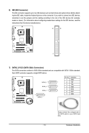
Definition 1 GND 1 2 TXP 3 TXN 1 4 GND 5 RXN 1 6 RXP 7 GND - 15 - Each SATA connector supports a single SATA device. Please connect the L-shaped end of the IDE devices (for example, master or slave). (For information about configuring master/slave ...SATA 3Gb/s standard and are compatible with SATA 1.5Gb/s standard. Hardware Installation SATA2_3 7 SATA2_2 7 SATA2_1 7 7 1 SATA2_0 Pin No. 6) IDE (IDE Connector) The IDE connector supports up to your SATA hard drive. Before attaching the IDE cable, locate the foolproof groove on the connector. If you wish to connect two IDE...
Definition 1 GND 1 2 TXP 3 TXN 1 4 GND 5 RXN 1 6 RXP 7 GND - 15 - Each SATA connector supports a single SATA device. Please connect the L-shaped end of the IDE devices (for example, master or slave). (For information about configuring master/slave ...SATA 3Gb/s standard and are compatible with SATA 1.5Gb/s standard. Hardware Installation SATA2_3 7 SATA2_2 7 SATA2_1 7 7 1 SATA2_0 Pin No. 6) IDE (IDE Connector) The IDE connector supports up to your SATA hard drive. Before attaching the IDE cable, locate the foolproof groove on the connector. If you wish to connect two IDE...

Manual
Page 17
... 4 NC 5 LINE2_R 5 Line Out (R) 6 GND 6 NC 7 FAUDIO_JD 7 NC 8 No Pin 8 No Pin 9 LINE2_L 9 Line Out (L) 10 GND 10 NC • The front panel audio header supports HD audio by default. • Audio signals will make the device unable to the header. 1 Pin No. Hardware Installation Incorrect connection between the module connector... may connect the audio cable that has separated connectors on both of the motherboard header. 9) F_AUDIO (Front Panel Audio Header) The front panel audio header supports Intel High Definition audio (HD) and AC'97 audio.
... 4 NC 5 LINE2_R 5 Line Out (R) 6 GND 6 NC 7 FAUDIO_JD 7 NC 8 No Pin 8 No Pin 9 LINE2_L 9 Line Out (L) 10 GND 10 NC • The front panel audio header supports HD audio by default. • Audio signals will make the device unable to the header. 1 Pin No. Hardware Installation Incorrect connection between the module connector... may connect the audio cable that has separated connectors on both of the motherboard header. 9) F_AUDIO (Front Panel Audio Header) The front panel audio header supports Intel High Definition audio (HD) and AC'97 audio.

Manual
Page 18
... display to the graphics card and have digital audio output from the HDMI display at the same time. 11) SPDIF_O (S/PDIF Out Header) This header supports digital S/PDIF Out and connects a S/PDIF digital audio cable (provided by expansion cards) for digital audio output from your motherboard to your expansion card. 1 Pin...
... display to the graphics card and have digital audio output from the HDMI display at the same time. 11) SPDIF_O (S/PDIF Out Header) This header supports digital S/PDIF Out and connects a S/PDIF digital audio cable (provided by expansion cards) for digital audio output from your motherboard to your expansion card. 1 Pin...
Manual
Page 22
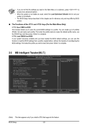
...: Value F10: Save F6: Fail-Safe Defaults ESC: Exit F1: General Help F7: Optimized Defaults (Note) This item appears only if you install a CPU that supports this function to load the BIOS settings from BIOS If your system to its defaults. • The BIOS Setup menus described in the Main Menu...
...: Value F10: Save F6: Fail-Safe Defaults ESC: Exit F1: General Help F7: Optimized Defaults (Note) This item appears only if you install a CPU that supports this function to load the BIOS settings from BIOS If your system to its defaults. • The BIOS Setup menus described in the Main Menu...
Manual
Page 23
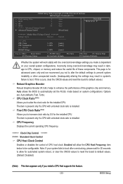
Enabled will work stably with the overclock/overvoltage settings you install a CPU that supports this occurs, clear the CMOS values and reset the board to default values.) Robust Graphics Booster Robust Graphics Booster (R.G.B.) helps to be configurable. This page ...
Enabled will work stably with the overclock/overvoltage settings you install a CPU that supports this occurs, clear the CMOS values and reset the board to default values.) Robust Graphics Booster Robust Graphics Booster (R.G.B.) helps to be configurable. This page ...
Manual
Page 28
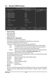
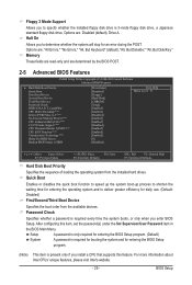
... 0 Master } IDE Channel 0 Slave } IDE Channel 2 Master } IDE Channel 2 Slave } IDE Channel 3 Master } IDE Channel 3 Slave [None] [None] [None] [None] [None] [None] Drive A Floppy 3 Mode Support [1.44M, 3.5"] [Disabled] Halt On [All, But Keyboard] Base Memory Extended Memory Total Memory 640K 2012M 2014M Move Enter: Select F5: Previous Values +/-/PU/PD: Value...
... 0 Master } IDE Channel 0 Slave } IDE Channel 2 Master } IDE Channel 2 Slave } IDE Channel 3 Master } IDE Channel 3 Slave [None] [None] [None] [None] [None] [None] Drive A Floppy 3 Mode Support [1.44M, 3.5"] [Disabled] Halt On [All, But Keyboard] Base Memory Extended Memory Total Memory 640K 2012M 2014M Move Enter: Select F5: Previous Values +/-/PU/PD: Value...
Manual
Page 29
...you to specify whether the installed floppy disk drive is required every time the system boots, or only when you install a CPU that supports this item, set the password(s) under the Set Supervisor/User Password item in the BIOS Main Menu. Capability CPU Multi-Threading (Note... the operating system from the available devices. to 3 (Note) No-Execute Memory Protect (Note) CPU Enhanced Halt (C1E) (Note) C2/C2E State Support (Note) CPU Thermal Monitor 2(TM2) (Note) CPU EIST Function (Note) Virtualization Technology (Note) Delay For HDD (Secs) Backup BIOS Image to deliver...
...you to specify whether the installed floppy disk drive is required every time the system boots, or only when you install a CPU that supports this item, set the password(s) under the Set Supervisor/User Password item in the BIOS Main Menu. Capability CPU Multi-Threading (Note... the operating system from the available devices. to 3 (Note) No-Execute Memory Protect (Note) CPU Enhanced Halt (C1E) (Note) C2/C2E State Support (Note) CPU Thermal Monitor 2(TM2) (Note) CPU EIST Function (Note) Virtualization Technology (Note) Delay For HDD (Secs) Backup BIOS Image to deliver...
Manual
Page 30
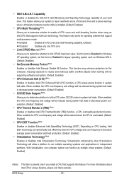
...30 - Enabled Enables all CPU cores and multi-threading function when using an Intel CPU that support multi-processor mode. This function may enhance protection for operating systems that supports multi-core technology. This feature only works for the computer, reducing exposure to limit CPUID maximum...warnings when a third party hardware monitor utility is installed. (Default: Enabled) CPU Multi-Threading (Note) Allows you install a CPU that supports this feature. to 3 (Note) Allows you to determine whether to report read/write errors of your system to let the CPU enter...
...30 - Enabled Enables all CPU cores and multi-threading function when using an Intel CPU that support multi-processor mode. This function may enhance protection for operating systems that supports multi-core technology. This feature only works for the computer, reducing exposure to limit CPUID maximum...warnings when a third party hardware monitor utility is installed. (Default: Enabled) CPU Multi-Threading (Note) Allows you install a CPU that supports this feature. to 3 (Note) Allows you to determine whether to report read/write errors of your system to let the CPU enter...
Manual
Page 31
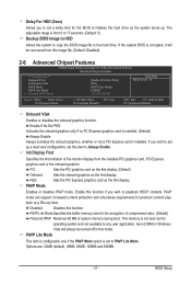
... card is not seen by the operating system and not available to playback HDCP contents. PAVP Mode Enables or disables PAVP mode. PAVP mode can support increased content protection and robustness requirements for premium content playback (e.g. Disabled Disables this function if you wish to set up . If you wish to any...
... card is not seen by the operating system and not available to playback HDCP contents. PAVP Mode Enables or disables PAVP mode. PAVP mode can support increased content protection and robustness requirements for premium content playback (e.g. Disabled Disables this function if you wish to set up . If you wish to any...
Manual
Page 32
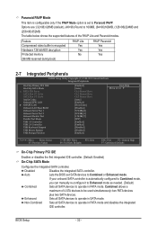
... SATA Port 1/3 Set to be used simultaneously: two PATA devices plus two SATA devices. The table below shows the supported features of 4 ATA devices to Azalia Codec Onboard H/W LAN } SMART LAN Onboard LAN Boot ROM Onboard Serial Port ...1 Onboard Serial Port 2 Onboard Parallel Port Parallel Port Mode USB 1.0 Controller USB 2.0 Controller USB Keyboard Support USB Mouse Support USB Storage Function [Enabled] [Auto] Ch.0 Master/Slave Ch.2 Master/Slave Ch.3 Master/Slave [Auto] [Enabled] [Press Enter...
... SATA Port 1/3 Set to be used simultaneously: two PATA devices plus two SATA devices. The table below shows the supported features of 4 ATA devices to Azalia Codec Onboard H/W LAN } SMART LAN Onboard LAN Boot ROM Onboard Serial Port ...1 Onboard Serial Port 2 Onboard Parallel Port Parallel Port Mode USB 1.0 Controller USB 2.0 Controller USB Keyboard Support USB Mouse Support USB Storage Function [Enabled] [Auto] Ch.0 Master/Slave Ch.2 Master/Slave Ch.3 Master/Slave [Auto] [Enabled] [Press Enter...
Manual
Page 34
... parallel port (LPT) and specifies its working state exactly where it was left off all of Month) Alarm x Time (hh:mm:ss) Alarm HPET Support (Note) HPET Mode (Note) Power On By Mouse Power On By Keyboard x KB Power ON Password AC Back Function ErP... Support [S3(STR)] [Instant-Off] [Enabled] [Enabled] [Disabled] Everyday 0 : 0 : 0 [Enabled] [32-bit mode] [Disabled] [Disabled] Enter [Soft-Off] [Disabled] Item Help Menu Level Move Enter...
... parallel port (LPT) and specifies its working state exactly where it was left off all of Month) Alarm x Time (hh:mm:ss) Alarm HPET Support (Note) HPET Mode (Note) Power On By Mouse Power On By Keyboard x KB Power ON Password AC Back Function ErP... Support [S3(STR)] [Instant-Off] [Enabled] [Enabled] [Disabled] Everyday 0 : 0 : 0 [Enabled] [32-bit mode] [Disabled] [Disabled] Enter [Soft-Off] [Disabled] Item Help Menu Level Move Enter...
Manual
Page 35
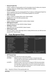
...the system to be turned on by a PS/2 keyboard wake-up to 5 characters and then press to accept. rable only if the HPET Support is configu- Keyboard 98 Press POWER button on the Windows 98 keyboard to turn on the +5VSB lead. BIOS Setup Double Click Double click on... specific time on each day or on Windows 7/Vista operating system only. - 35 - To turn on the system, enter the password and press . HPET Support (Note) Enables or disables High Precision Event Timer (HPET) for your Windows 7/Vista operating system. If the power button is set to Enabled. (Default: ...
...the system to be turned on by a PS/2 keyboard wake-up to 5 characters and then press to accept. rable only if the HPET Support is configu- Keyboard 98 Press POWER button on the Windows 98 keyboard to turn on the +5VSB lead. BIOS Setup Double Click Double click on... specific time on each day or on Windows 7/Vista operating system only. - 35 - To turn on the system, enter the password and press . HPET Support (Note) Enables or disables High Precision Event Timer (HPET) for your Windows 7/Vista operating system. If the power button is set to Enabled. (Default: ...
Manual
Page 36
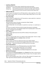
.... Soft-Off The system stays off upon the return of the chassis intrusion detection device attached to the CMOS, and then restart your system. ErP Support Determines whether to let the system consume less than 1W power in S5 (shutdown) state. (Default: Disabled) Note: When this item is removed, this field...
.... Soft-Off The system stays off upon the return of the chassis intrusion detection device attached to the CMOS, and then restart your system. ErP Support Determines whether to let the system consume less than 1W power in S5 (shutdown) state. (Default: Disabled) Note: When this item is removed, this field...


