Manual
Page 1
GA-G33M-S2L LGA775 socket motherboard for Intel® CoreTM processor family/ Intel® Pentium® processor family/Intel® Celeron® processor family User's Manual Rev. 1001 12ME-G33MS2L-1001R
GA-G33M-S2L LGA775 socket motherboard for Intel® CoreTM processor family/ Intel® Pentium® processor family/Intel® Celeron® processor family User's Manual Rev. 1001 12ME-G33MS2L-1001R
Manual
Page 2
Motherboard GA-G33M-S2L Oct. 22, 2007 Motherboard GA-G33M-S2L Oct. 22, 2007
Motherboard GA-G33M-S2L Oct. 22, 2007 Motherboard GA-G33M-S2L Oct. 22, 2007
Manual
Page 3
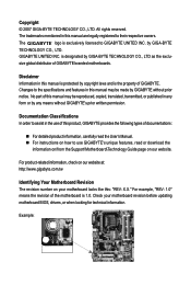
...- Disclaimer Information in any form or by any means without prior notice. For product-related information, check on our website at: http://www.gigabyte.com.tw Identifying Your Motherboard Revision The revision number on our website. The trademarks mentioned in the use of this manual is 1.0. is designated by copyright laws and...
...- Disclaimer Information in any form or by any means without prior notice. For product-related information, check on our website at: http://www.gigabyte.com.tw Identifying Your Motherboard Revision The revision number on our website. The trademarks mentioned in the use of this manual is 1.0. is designated by copyright laws and...
Manual
Page 4
Table of Contents Box Contents ...6 OptionalItems...6 GA-G33M-S2L Motherboard Layout 7 Block Diagram...8 Chapter 1 Hardware Installation 9 1-1 Installation Precautions 9 1-2 Product Specifications 10 1-3 Installing the CPU and CPU Cooler 13 1-3-1 Installing the CPU 13 1-3-2 Installing the CPU ...
Table of Contents Box Contents ...6 OptionalItems...6 GA-G33M-S2L Motherboard Layout 7 Block Diagram...8 Chapter 1 Hardware Installation 9 1-1 Installation Precautions 9 1-2 Product Specifications 10 1-3 Installing the CPU and CPU Cooler 13 1-3-1 Installing the CPU 13 1-3-2 Installing the CPU ...
Manual
Page 6
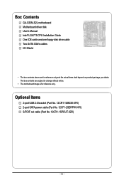
Optional Items 2-port USB 2.0 bracket (Part No. 12CR1-1UB030-51R) 2-port SATA power cable (Part No. 12CF1-2SERPW-01R) S/PDIF out cable (Part No. 12CR1-1SPOUT-02R) - 6 - Box Contents GA-G33M-S2L motherboard Motherboard driver disk User's Manual Intel® LGA775 CPU Installation Guide One IDE cable and one floppy disk drive cable Two SATA 3Gb/s cables I/O Shield • The box contents above are subject to change without notice. • The motherboard image is for reference only and the actual items shall depend on product package you obtain. The box contents are for reference only.
Optional Items 2-port USB 2.0 bracket (Part No. 12CR1-1UB030-51R) 2-port SATA power cable (Part No. 12CF1-2SERPW-01R) S/PDIF out cable (Part No. 12CR1-1SPOUT-02R) - 6 - Box Contents GA-G33M-S2L motherboard Motherboard driver disk User's Manual Intel® LGA775 CPU Installation Guide One IDE cable and one floppy disk drive cable Two SATA 3Gb/s cables I/O Shield • The box contents above are subject to change without notice. • The motherboard image is for reference only and the actual items shall depend on product package you obtain. The box contents are for reference only.
Manual
Page 7
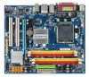
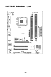
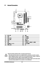
GA-G33M-S2L Motherboard Layout COMA KB_MS ATX_12V LGA775 DDRII1 DDRII2 CPU_FAN LPT VGA USB R_USB IDE ATX CI CLR_CMOS GA-G33M-S2L DDRII3 DDRII4 LAN AUDIO F_AUDIO RTL8111B PCIE_1 PCIE_16 IT8718 PCI1 PCI2 CODEC CD_IN SPDIF_O FDD Intel® G33 BAT MBIOS Intel® ICH9 SATAII0 SATAII1 SATAII4 SATAII5 SYS_FAN PWR_LED F_USB3F_USB2 F_USB1 F_PANEL - 7 -
GA-G33M-S2L Motherboard Layout COMA KB_MS ATX_12V LGA775 DDRII1 DDRII2 CPU_FAN LPT VGA USB R_USB IDE ATX CI CLR_CMOS GA-G33M-S2L DDRII3 DDRII4 LAN AUDIO F_AUDIO RTL8111B PCIE_1 PCIE_16 IT8718 PCI1 PCI2 CODEC CD_IN SPDIF_O FDD Intel® G33 BAT MBIOS Intel® ICH9 SATAII0 SATAII1 SATAII4 SATAII5 SYS_FAN PWR_LED F_USB3F_USB2 F_USB1 F_PANEL - 7 -
Manual
Page 9
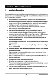
... the computer system on an uneven surface. • Do not place the computer system in a high-temperature environment. • Turning on the motherboard, make sure they are uncertain about any metal leads or connectors. • It is best to the use of electrostatic discharge (ESD). Hardware ... ESD wrist strap, keep your hands dry and first touch a metal object to eliminate static electricity. • Prior to installing the motherboard, please have it on top of an antistatic pad or within an electrostatic shielding container. • Before unplugging the power supply cable from...
... the computer system on an uneven surface. • Do not place the computer system in a high-temperature environment. • Turning on the motherboard, make sure they are uncertain about any metal leads or connectors. • It is best to the use of electrostatic discharge (ESD). Hardware ... ESD wrist strap, keep your hands dry and first touch a metal object to eliminate static electricity. • Prior to installing the motherboard, please have it on top of an antistatic pad or within an electrostatic shielding container. • Before unplugging the power supply cable from...
Manual
Page 10
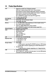
... Extreme Edition/Intel® Pentium® 4 processor/ Intel® Celeron® processor in the LGA 775 package (Go to GIGABYTE's website for the latest CPU support list.) Š L2 cache varies with CPU Š 1333/1066/800 MHz FSB Š... memory (Note 1) Š Dual channel memory architecture Š Support for DDR2 800/667 MHz memory modules (Go to GIGABYTE's website for the latest memory support list.) Š Integrated in the North Bridge Š Realtek ALC662 codec Š High...the back panel, 6 via the USB brackets connected to the internal USB headers) GA-G33M-S2L Motherboard - 10 -
... Extreme Edition/Intel® Pentium® 4 processor/ Intel® Celeron® processor in the LGA 775 package (Go to GIGABYTE's website for the latest CPU support list.) Š L2 cache varies with CPU Š 1333/1066/800 MHz FSB Š... memory (Note 1) Š Dual channel memory architecture Š Support for DDR2 800/667 MHz memory modules (Go to GIGABYTE's website for the latest memory support list.) Š Integrated in the North Bridge Š Realtek ALC662 codec Š High...the back panel, 6 via the USB brackets connected to the internal USB headers) GA-G33M-S2L Motherboard - 10 -
Manual
Page 12
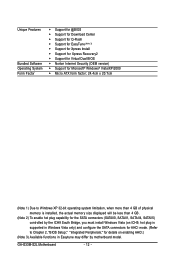
GA-G33M-S2L Motherboard - 12 - Unique Features Bundled Software Operating System Form Factor Š Support for @BIOS Š Support for Download Center Š Support for Q-Flash Š Support for ... SATA connectors for AHCI mode. (Refer to Chapter 2, "BIOS Setup," "Integrated Peripherals," for details on enabling AHCI.) (Note 3) Available functions in Easytune may differ by motherboard model.
GA-G33M-S2L Motherboard - 12 - Unique Features Bundled Software Operating System Form Factor Š Support for @BIOS Š Support for Download Center Š Support for Q-Flash Š Support for ... SATA connectors for AHCI mode. (Refer to Chapter 2, "BIOS Setup," "Integrated Peripherals," for details on enabling AHCI.) (Note 3) Available functions in Easytune may differ by motherboard model.
Manual
Page 13
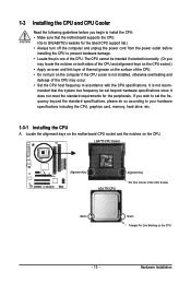
... CPU, graphics card, memory, hard drive, etc. 1-3-1 Installing the CPU A. Locate the alignment keys on the motherboard CPU socket and the notches on the CPU - 13 - mended that the motherboard supports the CPU. (Go to GIGABYTE's website for the peripherals. Hardware Installation LGA775 CPU Socket Alignment Key LGA 775 CPU Alignment Key Pin...
... CPU, graphics card, memory, hard drive, etc. 1-3-1 Installing the CPU A. Locate the alignment keys on the motherboard CPU socket and the notches on the CPU - 13 - mended that the motherboard supports the CPU. (Go to GIGABYTE's website for the peripherals. Hardware Installation LGA775 CPU Socket Alignment Key LGA 775 CPU Alignment Key Pin...
Manual
Page 14
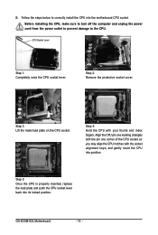
... to turn off the computer and unplug the power cord from the power outlet to prevent damage to correctly install the CPU into the motherboard CPU socket. GA-G33M-S2L Motherboard - 14 - B. Align the CPU pin one marking (triangle) with the pin one corner of the CPU socket (or you may align the CPU notches...
... to turn off the computer and unplug the power cord from the power outlet to prevent damage to correctly install the CPU into the motherboard CPU socket. GA-G33M-S2L Motherboard - 14 - B. Align the CPU pin one marking (triangle) with the pin one corner of the CPU socket (or you may align the CPU notches...
Manual
Page 15
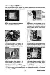
... on the male push pin. (Turning the push pin along the direction of the CPU cooler to the CPU fan header (CPU_FAN) on the motherboard. Check that the Male and Female push pins are joined closely. (Refer to your CPU cooler installation manual for instructions on installing the cooler.)...cooler and CPU may damage the CPU. - 15 - 1-3-2 Installing the CPU Cooler Follow the steps below to correctly install the CPU cooler on the motherboard. (The following procedure uses Intel® boxed cooler as the picture above, the installation is complete. If the push pin is inserted as the ...
... on the male push pin. (Turning the push pin along the direction of the CPU cooler to the CPU fan header (CPU_FAN) on the motherboard. Check that the Male and Female push pins are joined closely. (Refer to your CPU cooler installation manual for instructions on installing the cooler.)...cooler and CPU may damage the CPU. - 15 - 1-3-2 Installing the CPU Cooler Follow the steps below to correctly install the CPU cooler on the motherboard. (The following procedure uses Intel® boxed cooler as the picture above, the installation is complete. If the push pin is inserted as the ...
Manual
Page 16
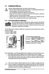
...in Dual Channel mode/performance. When memory modules of the same capacity, brand, speed, and chips be used . (Go to GIGABYTE's website for the latest memory support list.) • Always turn off the computer and unplug the power cord from the power...installed in only one DDR2 memory module is recommended that the motherboard supports the memory. 1-4 Installing the Memory Read the following : Channel 0: DDRII1, DDRII2 Channel 1: DDRII3, DDRII4 Dual Channel Memory Configurations Table DDRII1 DDRII2 DDRII3 Two Modules DS/SS - - DS/SS - - GA-G33M-S2L Motherboard - 16 -
...in Dual Channel mode/performance. When memory modules of the same capacity, brand, speed, and chips be used . (Go to GIGABYTE's website for the latest memory support list.) • Always turn off the computer and unplug the power cord from the power...installed in only one DDR2 memory module is recommended that the motherboard supports the memory. 1-4 Installing the Memory Read the following : Channel 0: DDRII1, DDRII2 Channel 1: DDRII3, DDRII4 Dual Channel Memory Configurations Table DDRII1 DDRII2 DDRII3 Two Modules DS/SS - - DS/SS - - GA-G33M-S2L Motherboard - 16 -
Manual
Page 17
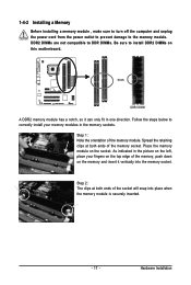
... , make sure to turn off the computer and unplug the power cord from the power outlet to prevent damage to install DDR2 DIMMs on this motherboard. Notch DDR2 DIMM A DDR2 memory module has a notch, so it vertically into place when the memory module is securely inserted. - 17 - As indicated in the...
... , make sure to turn off the computer and unplug the power cord from the power outlet to prevent damage to install DDR2 DIMMs on this motherboard. Notch DDR2 DIMM A DDR2 memory module has a notch, so it vertically into place when the memory module is securely inserted. - 17 - As indicated in the...
Manual
Page 18
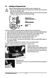
..., replace the chassis cover(s). 6. Install the driver provided with a screw. 5. If necessary, go to BIOS Setup to install an expansion card: • Make sure the motherboard supports the expansion card. Secure the card's metal bracket to correctly install your expansion card(s). 7. Carefully read the manual that supports your expansion card. •... the PCI Express x16 slot. Example: Installing and Removing a PCI Express x16 Graphics Card: • Installing a Graphics Card: Gently push down on your operating system. GA-G33M-S2L Motherboard - 18 -
..., replace the chassis cover(s). 6. Install the driver provided with a screw. 5. If necessary, go to BIOS Setup to install an expansion card: • Make sure the motherboard supports the expansion card. Secure the card's metal bracket to correctly install your expansion card(s). 7. Carefully read the manual that supports your expansion card. •... the PCI Express x16 slot. Example: Installing and Removing a PCI Express x16 Graphics Card: • Installing a Graphics Card: Gently push down on your operating system. GA-G33M-S2L Motherboard - 18 -
Manual
Page 19
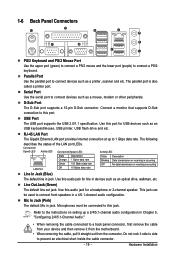
... The USB port supports the USB 2.0/1.1 specification. The following describes the states of the LAN port LEDs. Do not rock it straight out from the motherboard. • When removing the cable, pull it side to side to connect devices such as an USB keyboard/mouse, USB printer, USB flash drive and...
... The USB port supports the USB 2.0/1.1 specification. The following describes the states of the LAN port LEDs. Do not rock it straight out from the motherboard. • When removing the cable, pull it side to side to connect devices such as an USB keyboard/mouse, USB printer, USB flash drive and...
Manual
Page 20
... sure to the connector on the motherboard. Unplug the power cord from the power outlet to prevent damage to the devices. • After installing the device and before connecting external devices: • First make sure the device cable has been securely attached to turn off the devices and your computer. GA-G33M-S2L Motherboard - 20 -
... sure to the connector on the motherboard. Unplug the power cord from the power outlet to prevent damage to the devices. • After installing the device and before connecting external devices: • First make sure the device cable has been securely attached to turn off the devices and your computer. GA-G33M-S2L Motherboard - 20 -
Manual
Page 21
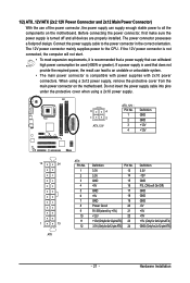
... cable into pins under the protective cover when using a 2x12 power supply, remove the protective cover from the main power connector on the motherboard. Hardware Installation The power connector possesses a foolproof design. If a power supply is used that can withstand high power consumption be used (400W... or greater). Before connecting the power connector, first make sure the power supply is turned off and all the components on the motherboard. 1/2) ATX_12V/ATX (2x2 12V Power Connector and 2x12 Main Power Connector) With the use of the power connector, the power supply can...
... cable into pins under the protective cover when using a 2x12 power supply, remove the protective cover from the main power connector on the motherboard. Hardware Installation The power connector possesses a foolproof design. If a power supply is used that can withstand high power consumption be used (400W... or greater). Before connecting the power connector, first make sure the power supply is turned off and all the components on the motherboard. 1/2) ATX_12V/ATX (2x2 12V Power Connector and 2x12 Main Power Connector) With the use of the power connector, the power supply can...
Manual
Page 22
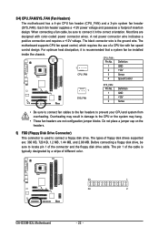
... Most fans are not configuration jumper blocks. Overheating may hang. • These fan headers are designed with fan speed control design. The motherboard supports CPU fan speed control, which requires the use of the connector and the floppy disk drive cable. Definition 1 1 GND 2 +... For optimum heat dissipation, it in damage to prevent your CPU and system from overheating. The types of different color. 33 1 34 2 GA-G33M-S2L Motherboard - 22 - The pin 1 of the cable is the ground wire. CPU_FAN : Pin No. Each fan header supplies a +12V power ...
... Most fans are not configuration jumper blocks. Overheating may hang. • These fan headers are designed with fan speed control design. The motherboard supports CPU fan speed control, which requires the use of the connector and the floppy disk drive cable. Definition 1 1 GND 2 +... For optimum heat dissipation, it in damage to prevent your CPU and system from overheating. The types of different color. 33 1 34 2 GA-G33M-S2L Motherboard - 22 - The pin 1 of the cable is the ground wire. CPU_FAN : Pin No. Each fan header supplies a +12V power ...
Manual
Page 24
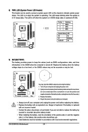
... as BIOS configurations, date, and time information) in S3/S4 sleep state or powered off your computer and unplug the power cord. 2. Replace the battery. 4. GA-G33M-S2L Motherboard - 24 - Pin No. Definition 1 MPD+ 2 MPD- 1 3 MPD- You may be lost. Gently remove the battery from the battery holder and wait for 5 seconds.) 3. 8) PWR_LED (System...
... as BIOS configurations, date, and time information) in S3/S4 sleep state or powered off your computer and unplug the power cord. 2. Replace the battery. 4. GA-G33M-S2L Motherboard - 24 - Pin No. Definition 1 MPD+ 2 MPD- 1 3 MPD- You may be lost. Gently remove the battery from the battery holder and wait for 5 seconds.) 3. 8) PWR_LED (System...


