Manual
Page 1
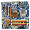
GA-G33M-S2H LGA775 socket motherboard for Intel® CoreTM processor family/ Intel® Pentium® processor family/Intel® Celeron® processor family User's Manual Rev. 1001 12ME-G33MS2H-1001R * The WEEE marking on the product indicates this product must not be disposed of with user's other household waste and must be handed over to a designated collection point for the recycling of waste electrical and electronic equipment!! * The WEEE marking applies only in European Union's member states.
GA-G33M-S2H LGA775 socket motherboard for Intel® CoreTM processor family/ Intel® Pentium® processor family/Intel® Celeron® processor family User's Manual Rev. 1001 12ME-G33MS2H-1001R * The WEEE marking on the product indicates this product must not be disposed of with user's other household waste and must be handed over to a designated collection point for the recycling of waste electrical and electronic equipment!! * The WEEE marking applies only in European Union's member states.

Manual
Page 2
Motherboard GA-G33M-S2H Jul. 13, 2007 Motherboard GA-G33M-S2H Jul. 13, 2007
Motherboard GA-G33M-S2H Jul. 13, 2007 Motherboard GA-G33M-S2H Jul. 13, 2007

Manual
Page 3
...Changes to the specifications and features in this manual are legally registered to GIGABYTE UNITED INC. The trademarks mentioned in this product, GIGABYTE provides the following types of the motherboard is exclusively licensed to their respective owners. is designated by GIGA-BYTE TECHNOLOGY... made by copyright laws and is protected by GIGABYTE without GIGABYTE's prior written permission. The logo is 1.0. For product-related information, check on our website at: http://www.gigabyte.com.tw Identifying Your Motherboard Revision The revision number on how to assist...
...Changes to the specifications and features in this manual are legally registered to GIGABYTE UNITED INC. The trademarks mentioned in this product, GIGABYTE provides the following types of the motherboard is exclusively licensed to their respective owners. is designated by GIGA-BYTE TECHNOLOGY... made by copyright laws and is protected by GIGABYTE without GIGABYTE's prior written permission. The logo is 1.0. For product-related information, check on our website at: http://www.gigabyte.com.tw Identifying Your Motherboard Revision The revision number on how to assist...
Manual
Page 4
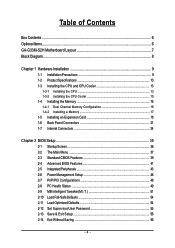
Table of Contents Box Contents ...6 OptionalItems ...6 GA-G33M-S2H Motherboard Layout 7 Block Diagram ...8 Chapter 1 Hardware Installation 9 1-1 Installation Precautions 9 1-2 Product Specifications 10 1-3 Installing the CPU and CPU Cooler 13 1-3-1 Installing the CPU 13 1-3-2 Installing the CPU ...
Table of Contents Box Contents ...6 OptionalItems ...6 GA-G33M-S2H Motherboard Layout 7 Block Diagram ...8 Chapter 1 Hardware Installation 9 1-1 Installation Precautions 9 1-2 Product Specifications 10 1-3 Installing the CPU and CPU Cooler 13 1-3-1 Installing the CPU 13 1-3-2 Installing the CPU ...
Manual
Page 6
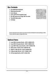
... in cable (Part No. 12CR1-1SPDIN-01/R) COM port cable (Part No. 12CF1-1CM001-31/R) LPT port cable (Part No. 12CF1-1LP001-01R) - 6 - Box Contents GA-G33M-S2H motherboard Motherboard driver disk User's Manual Intel® LGA775 CPU Installation Guide One IDE cable and one floppy disk drive cable Two SATA 3Gb/s cables I/O Shield The...
... in cable (Part No. 12CR1-1SPDIN-01/R) COM port cable (Part No. 12CF1-1CM001-31/R) LPT port cable (Part No. 12CF1-1LP001-01R) - 6 - Box Contents GA-G33M-S2H motherboard Motherboard driver disk User's Manual Intel® LGA775 CPU Installation Guide One IDE cable and one floppy disk drive cable Two SATA 3Gb/s cables I/O Shield The...
Manual
Page 9
...has been turned off. • Before turning on the power, make sure they are connected tightly and securely. • When handling the motherboard, avoid touching any installation steps or have it on top of an antistatic pad or within a electrostatic shielding container. • Before unplugging the...Before using the product, please verify that all cables and power connectors of your hardware components are connected. • To prevent damage to the motherboard, do not have an ESD wrist strap, keep your hands dry and first touch a metal object to eliminate static electricity. • Prior...
...has been turned off. • Before turning on the power, make sure they are connected tightly and securely. • When handling the motherboard, avoid touching any installation steps or have it on top of an antistatic pad or within a electrostatic shielding container. • Before unplugging the...Before using the product, please verify that all cables and power connectors of your hardware components are connected. • To prevent damage to the motherboard, do not have an ESD wrist strap, keep your hands dry and first touch a metal object to eliminate static electricity. • Prior...
Manual
Page 10
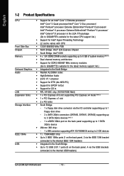
... processor Extreme Edition/Intel® Pentium® 4 processor/ Intel® Celeron® D processor in the LGA 775 package (Go to GIGABYTE's website for the latest CPU support list.) Š Support for the latest memory support list.) Š Integrated in the South Bridge &#...GIGABYTE's website for Intel® Hyper-Threading Technology Š L2 cache varies with CPU Š 1333/1066/800 MHz FSB Š North Bridge: Intel® G33 Express Chipset Š South Bridge: Intel® ICH9 Š 4 x 1.8V DDR2 DIMM sockets supporting up to the internal USB headers) GA-G33M-S2H Motherboard...
... processor Extreme Edition/Intel® Pentium® 4 processor/ Intel® Celeron® D processor in the LGA 775 package (Go to GIGABYTE's website for the latest CPU support list.) Š Support for the latest memory support list.) Š Integrated in the South Bridge &#...GIGABYTE's website for Intel® Hyper-Threading Technology Š L2 cache varies with CPU Š 1333/1066/800 MHz FSB Š North Bridge: Intel® G33 Express Chipset Š South Bridge: Intel® ICH9 Š 4 x 1.8V DDR2 DIMM sockets supporting up to the internal USB headers) GA-G33M-S2H Motherboard...
Manual
Page 12
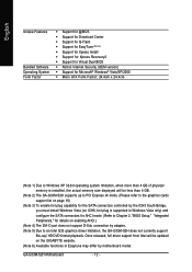
GA-G33M-S2H Motherboard - 12 - Once released, full driver support from Intel will be updated on enabling AHCI.) (Note 4) The DVI-D port does not support D-Sub connection by motherboard model. English Unique Features Bundled Software Operating System Form Factor Š Support for @BIOS Š ... Chapter 2, "BIOS Setup," "Integrated Peripherals," for details on the GIGABYTE website. (Note 6) Available functions in Easytune may differ by adapter. (Note 5) Due to an Intel G33 graphics driver limitation, the GA-G33M-S2H does not currently support Blu-ray/ HD DVD format playback.
GA-G33M-S2H Motherboard - 12 - Once released, full driver support from Intel will be updated on enabling AHCI.) (Note 4) The DVI-D port does not support D-Sub connection by motherboard model. English Unique Features Bundled Software Operating System Form Factor Š Support for @BIOS Š ... Chapter 2, "BIOS Setup," "Integrated Peripherals," for details on the GIGABYTE website. (Note 6) Available functions in Easytune may differ by adapter. (Note 5) Due to an Intel G33 graphics driver limitation, the GA-G33M-S2H does not currently support Blu-ray/ HD DVD format playback.

Manual
Page 13
...- Hyper-Threading Technology System Requirements: (Go to your hardware specifications including the CPU, graphics card, memory, hard drive, etc. Locate the alignment keys on the motherboard CPU socket and the notches on enabling the HT Technology.) 1-3-1 Installing the CPU A. If you begin to install the CPU: • Make sure that the...
...- Hyper-Threading Technology System Requirements: (Go to your hardware specifications including the CPU, graphics card, memory, hard drive, etc. Locate the alignment keys on the motherboard CPU socket and the notches on enabling the HT Technology.) 1-3-1 Installing the CPU A. If you begin to install the CPU: • Make sure that the...
Manual
Page 14
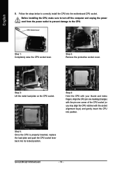
... fingers. Step 5: Once the CPU is properly inserted, replace the load plate and push the CPU socket lever back into the motherboard CPU socket. Step 2: Remove the protective socket cover. GA-G33M-S2H Motherboard - 14 - Step 4: Hold the CPU with the socket alignment keys) and gently insert the CPU into position. Step 3: Lift the metal...
... fingers. Step 5: Once the CPU is properly inserted, replace the load plate and push the CPU socket lever back into the motherboard CPU socket. Step 2: Remove the protective socket cover. GA-G33M-S2H Motherboard - 14 - Step 4: Hold the CPU with the socket alignment keys) and gently insert the CPU into position. Step 3: Lift the metal...

Manual
Page 15
... the contrary, is to install.) Step 3: Place the cooler atop the CPU, aligning the four push pins through the pin holes on the motherboard. Check that the Male and Female push pins are joined closely. (Refer to your CPU cooler installation manual for instructions on installing the cooler... CPU. Push down each push pin. English 1-3-2 Installing the CPU Cooler Follow the steps below to correctly install the CPU cooler on the motherboard. (The following procedure uses Intel® boxed cooler as the picture above, the installation is complete. If the push pin is inserted as...
... the contrary, is to install.) Step 3: Place the cooler atop the CPU, aligning the four push pins through the pin holes on the motherboard. Check that the Male and Female push pins are joined closely. (Refer to your CPU cooler installation manual for instructions on installing the cooler... CPU. Push down each push pin. English 1-3-2 Installing the CPU Cooler Follow the steps below to correctly install the CPU cooler on the motherboard. (The following procedure uses Intel® boxed cooler as the picture above, the installation is complete. If the push pin is inserted as...
Manual
Page 16
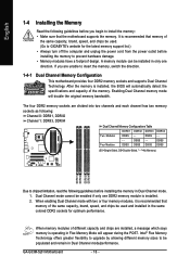
...the power cord from the power outlet before installing the memory to install the memory: • Make sure that the motherboard supports the memory. DS/SS - - GA-G33M-S2H Motherboard - 16 - It is installed, the BIOS will appear during the POST. After the memory is recommended that memory ...only one DDR2 memory module is recommended that memory of the same capacity, brand, speed, and chips be used . (Go to GIGABYTE's website for optimum performance. Intel® Flex Memory Technology offers greater flexibility to upgrade by allowing different memory sizes to insert the memory...
...the power cord from the power outlet before installing the memory to install the memory: • Make sure that the motherboard supports the memory. DS/SS - - GA-G33M-S2H Motherboard - 16 - It is installed, the BIOS will appear during the POST. After the memory is recommended that memory ...only one DDR2 memory module is recommended that memory of the same capacity, brand, speed, and chips be used . (Go to GIGABYTE's website for optimum performance. Intel® Flex Memory Technology offers greater flexibility to upgrade by allowing different memory sizes to insert the memory...
Manual
Page 17
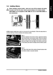
... DDR DIMMs. Be sure to install DDR2 DIMMs on the socket. Step 1: Note the orientation of the memory module. Place the memory module on this motherboard. Hardware Installation Follow the steps below to the memory module. As indicated in the memory sockets. Step 2: The clips at both ends of the socket...
... DDR DIMMs. Be sure to install DDR2 DIMMs on the socket. Step 1: Note the orientation of the memory module. Place the memory module on this motherboard. Hardware Installation Follow the steps below to the memory module. As indicated in the memory sockets. Step 2: The clips at both ends of the socket...
Manual
Page 18
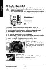
... to correctly install your expansion card(s). 7. Secure the card's metal bracket to the chassis back panel with the expansion card in the slot. 3. GA-G33M-S2H Motherboard - 18 - Remove the metal slot cover from the power outlet before you begin to install an expansion card: • Make sure the... motherboard supports the expansion card. Align the card with your card. After installing all expansion cards, replace the chassis cover(s). 6. Make sure the graphics ...
... to correctly install your expansion card(s). 7. Secure the card's metal bracket to the chassis back panel with the expansion card in the slot. 3. GA-G33M-S2H Motherboard - 18 - Remove the metal slot cover from the power outlet before you begin to install an expansion card: • Make sure the... motherboard supports the expansion card. Align the card with your card. After installing all expansion cards, replace the chassis cover(s). 6. Make sure the graphics ...
Manual
Page 20
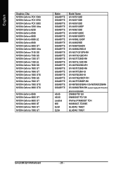
... NVIDIA Geforce 6600 GT NVIDIA Geforce 6600 GT NVIDIA Geforce 6800 GT NVIDIA Geforce 7600 GT NVIDIA Geforce 7900 GT Maker GIGABYTE GIGABYTE GIGABYTE GIGABYTE GIGABYTE GIGABYTE GIGABYTE GIGABYTE GIGABYTE GIGABYTE GIGABYTE GIGABYTE GIGABYTE GIGABYTE GIGABYTE GIGABYTE GIGABYTE GIGABYTE GIGABYTE GIGABYTE GIGABYTE GIGABYTE GIGABYTE ASUS ASUS Leadtek MSI ELSA ELSA Model Name GV-NX53128D GV-NX57128D GV-NX59128D GV-NX55128DP GV-NX62128D GV-NX65128DE GV... above is recommended) EN6600/TD/128 EN6600GT/TD/128 WinFast PX6600GT TDH NX6800GT-TD256E GLADIAC 760GT GLADIAC 790GT GA-G33M-S2H Motherboard - 20 -
... NVIDIA Geforce 6600 GT NVIDIA Geforce 6600 GT NVIDIA Geforce 6800 GT NVIDIA Geforce 7600 GT NVIDIA Geforce 7900 GT Maker GIGABYTE GIGABYTE GIGABYTE GIGABYTE GIGABYTE GIGABYTE GIGABYTE GIGABYTE GIGABYTE GIGABYTE GIGABYTE GIGABYTE GIGABYTE GIGABYTE GIGABYTE GIGABYTE GIGABYTE GIGABYTE GIGABYTE GIGABYTE GIGABYTE GIGABYTE GIGABYTE ASUS ASUS Leadtek MSI ELSA ELSA Model Name GV-NX53128D GV-NX57128D GV-NX59128D GV-NX55128DP GV-NX62128D GV-NX65128DE GV... above is recommended) EN6600/TD/128 EN6600GT/TD/128 WinFast PX6600GT TDH NX6800GT-TD256E GLADIAC 760GT GLADIAC 790GT GA-G33M-S2H Motherboard - 20 -
Manual
Page 22
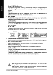
...Optical S/PDIF Out Connector This connector provides digital audio out to an external audio system that your device and then remove it from the motherboard. • When removing the cable, pull it side to side to prevent an electrical short inside the cable connector. Use this ...back panel connector, first remove the cable from the connector. Rear Speaker Out Jack (Black) Use this audio jack for an IEEE 1394a device. GA-G33M-S2H Motherboard - 22 - Speed LED Connection/ Activity LED Speed LED: State Description Orange 1 Gpbs data rate Green 100 Mpbs data rate Off 10 Mpbs ...
...Optical S/PDIF Out Connector This connector provides digital audio out to an external audio system that your device and then remove it from the motherboard. • When removing the cable, pull it side to side to prevent an electrical short inside the cable connector. Use this ...back panel connector, first remove the cable from the connector. Rear Speaker Out Jack (Black) Use this audio jack for an IEEE 1394a device. GA-G33M-S2H Motherboard - 22 - Speed LED Connection/ Activity LED Speed LED: State Description Orange 1 Gpbs data rate Green 100 Mpbs data rate Off 10 Mpbs ...
Manual
Page 23
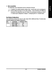
Hardware Installation Only microphones still MUST be connected to the default Mic in jack ( ). Dual Display Configurations: This motherboard provides three ports for video output: DVI-D, HDMI and D-Sub. The table below shows the supported dual display configurations. English Mic In Jack (Pink) The ...
Hardware Installation Only microphones still MUST be connected to the default Mic in jack ( ). Dual Display Configurations: This motherboard provides three ports for video output: DVI-D, HDMI and D-Sub. The table below shows the supported dual display configurations. English Mic In Jack (Pink) The ...
Manual
Page 24
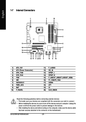
GA-G33M-S2H Motherboard - 24 - English 1-7 Internal Connectors 1 3 18 5 2 11 6 19 7 12 14 13 17 4 20 16 9 15 8 10 1) ATX_12V 2) ATX (Power Connector) 3) CPU_FAN 4) SYS_FAN 5) FDD 6) IDE 7) SATAII0/1/2 8) PWR_LED 9) ..., make sure your devices are compliant with the connectors you wish to connect. • Before installing the devices, be sure to the connector on the motherboard. Unplug the power cord from the power outlet to prevent damage to the devices. • After installing the device and before connecting external devices: •...
GA-G33M-S2H Motherboard - 24 - English 1-7 Internal Connectors 1 3 18 5 2 11 6 19 7 12 14 13 17 4 20 16 9 15 8 10 1) ATX_12V 2) ATX (Power Connector) 3) CPU_FAN 4) SYS_FAN 5) FDD 6) IDE 7) SATAII0/1/2 8) PWR_LED 9) ..., make sure your devices are compliant with the connectors you wish to connect. • Before installing the devices, be sure to the connector on the motherboard. Unplug the power cord from the power outlet to prevent damage to the devices. • After installing the device and before connecting external devices: •...
Manual
Page 25
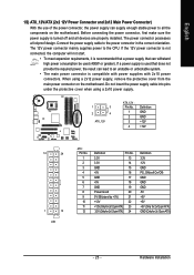
Before connecting the power connector, first make sure the power supply is turned off and all the components on the motherboard. If the 12V power connector is not connected, the computer will not start. • To meet expansion requirements, it is recommended that a power ... power supply cable into pins under the protective cover when using a 2x12 power supply, remove the protective cover from the main power connector on the motherboard. The power connector possesses a foolproof design. If a power supply is used (400W or greater). Connect the power supply cable to the CPU. The...
Before connecting the power connector, first make sure the power supply is turned off and all the components on the motherboard. If the 12V power connector is not connected, the computer will not start. • To meet expansion requirements, it is recommended that a power ... power supply cable into pins under the protective cover when using a 2x12 power supply, remove the protective cover from the main power connector on the motherboard. The power connector possesses a foolproof design. If a power supply is used (400W or greater). Connect the power supply cable to the CPU. The...
Manual
Page 26
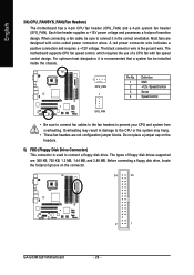
... drive. For optimum heat dissipation, it in damage to prevent your CPU and system from overheating. English 3/4) CPU_FAN/SYS_FAN (Fan Headers) The motherboard has a 4-pin CPU fan header (CPU_FAN) and a 4-pin system fan header (SYS_FAN). Overheating may hang. • These fan headers ...requires the use of floppy disk drives supported are designed with fan speed control design. Do not place a jumper cap on the connector. 34 33 2 1 GA-G33M-S2H Motherboard - 26 - When connecting a fan cable, be installed inside the chassis. 1 CPU_FAN 1 Pin No. 1 2 3 4 Definition GND +12V / ...
... drive. For optimum heat dissipation, it in damage to prevent your CPU and system from overheating. English 3/4) CPU_FAN/SYS_FAN (Fan Headers) The motherboard has a 4-pin CPU fan header (CPU_FAN) and a 4-pin system fan header (SYS_FAN). Overheating may hang. • These fan headers ...requires the use of floppy disk drives supported are designed with fan speed control design. Do not place a jumper cap on the connector. 34 33 2 1 GA-G33M-S2H Motherboard - 26 - When connecting a fan cable, be installed inside the chassis. 1 CPU_FAN 1 Pin No. 1 2 3 4 Definition GND +12V / ...


