
Manual
Page 1
GA-G31MF-S2 LGA775 socket motherboard for Intel® CoreTM processor family/ Intel® Pentium® processor family/Intel® Celeron® processor family User's Manual Rev. 1001 12ME-G31MFS2-1001R
GA-G31MF-S2 LGA775 socket motherboard for Intel® CoreTM processor family/ Intel® Pentium® processor family/Intel® Celeron® processor family User's Manual Rev. 1001 12ME-G31MFS2-1001R

Manual
Page 2
Motherboard GA-G31MF-S2 Jan. 9, 2008 Motherboard GA-G31MF-S2 Jan. 9, 2008
Motherboard GA-G31MF-S2 Jan. 9, 2008 Motherboard GA-G31MF-S2 Jan. 9, 2008
Manual
Page 3
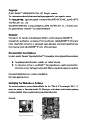
... specifications and features in this manual may be made by GIGABYTE without GIGABYTE's prior written permission. GIGABYTE UNITED INC. Check your motherboard looks like this product, GIGABYTE provides the following types of this manual is the property of this : "REV: X.X." All rights reserved. Changes to GIGABYTE UNITED INC. No part of documentations: „ For detailed product...
... specifications and features in this manual may be made by GIGABYTE without GIGABYTE's prior written permission. GIGABYTE UNITED INC. Check your motherboard looks like this product, GIGABYTE provides the following types of this manual is the property of this : "REV: X.X." All rights reserved. Changes to GIGABYTE UNITED INC. No part of documentations: „ For detailed product...

Manual
Page 4
Table of Contents Box Contents ...6 OptionalItems ...6 GA-G31MF-S2 Motherboard Layout 7 Block Diagram ...8 Chapter 1 Hardware Installation 9 1-1 Installation Precautions 9 1-2 Product Specifications 10 1-3 Installing the CPU and CPU Cooler 13 1-3-1 Installing the CPU 13 1-3-2 Installing the CPU ...
Table of Contents Box Contents ...6 OptionalItems ...6 GA-G31MF-S2 Motherboard Layout 7 Block Diagram ...8 Chapter 1 Hardware Installation 9 1-1 Installation Precautions 9 1-2 Product Specifications 10 1-3 Installing the CPU and CPU Cooler 13 1-3-1 Installing the CPU 13 1-3-2 Installing the CPU ...
Manual
Page 6
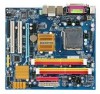
... are for reference only. Box Contents GA-G31MF-S2 motherboard Motherboard driver disk User's Manual Intel® LGA775 CPU Installation Guide One IDE cable and one floppy disk drive cable Two SATA 3Gb/s cables I/O Shield • The box contents above are subject to change without notice. • The motherboard image is for reference only and the...
... are for reference only. Box Contents GA-G31MF-S2 motherboard Motherboard driver disk User's Manual Intel® LGA775 CPU Installation Guide One IDE cable and one floppy disk drive cable Two SATA 3Gb/s cables I/O Shield • The box contents above are subject to change without notice. • The motherboard image is for reference only and the...

Manual
Page 7
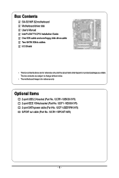
GA-G31MF-S2 Motherboard Layout KB_MS ATX_12V LGA775 CPU_FAN COMA LPT VGA USB_1394 USB_LAN AUDIO F_AUDIO PCIE_1 RTL8111C PCIE_16 IT8718 PCI1 CODEC PCI2 SPDIF_O CD_IN FDD Intel® G31 ATX IDE GA-G31MF-S2 DDRII1 DDRII2 DDRII3 DDRII4 BAT MBIOS CLR_CMOS F1_1394 SYS_FAN TSB43AB23 SATAII3 Intel® ICH7 SATAII2 SATAII1 SATAII0 CI PWR_LED F_USB1 F_USB2 F_PANEL - 7 -
GA-G31MF-S2 Motherboard Layout KB_MS ATX_12V LGA775 CPU_FAN COMA LPT VGA USB_1394 USB_LAN AUDIO F_AUDIO PCIE_1 RTL8111C PCIE_16 IT8718 PCI1 CODEC PCI2 SPDIF_O CD_IN FDD Intel® G31 ATX IDE GA-G31MF-S2 DDRII1 DDRII2 DDRII3 DDRII4 BAT MBIOS CLR_CMOS F1_1394 SYS_FAN TSB43AB23 SATAII3 Intel® ICH7 SATAII2 SATAII1 SATAII0 CI PWR_LED F_USB1 F_USB2 F_PANEL - 7 -

Manual
Page 9
... electrostatic shielding container. • Before unplugging the power supply cable from the power outlet before installing or removing the motherboard or other hardware components. • When connecting hardware components to the internal connectors on the computer power during the ... as a result of the product, please consult a certified computer technician. - 9 - Chapter 1 Hardware Installation 1-1 Installation Precautions The motherboard contains numerous delicate electronic circuits and components which can lead to damage to system components as well as physical harm to the user. &#...
... electrostatic shielding container. • Before unplugging the power supply cable from the power outlet before installing or removing the motherboard or other hardware components. • When connecting hardware components to the internal connectors on the computer power during the ... as a result of the product, please consult a certified computer technician. - 9 - Chapter 1 Hardware Installation 1-1 Installation Precautions The motherboard contains numerous delicate electronic circuits and components which can lead to damage to system components as well as physical harm to the user. &#...

Manual
Page 10
... to 4 GB of system memory (Note 1) Š Dual channel memory architecture Š Support for DDR2 800/667 MHz memory modules (Go to GIGABYTE's website for the latest memory support list.) Š Realtek AL662 codec Š High Definition Audio Š 2/4/5.1-channel Š Support for S/PDIF...) supporting up to 4 SATA 3Gb/s devices Š iTE IT8718 chip: - 1 x floppy disk drive connector supporting up to the internal USB headers) GA-G31MF-S2 Motherboard - 10 - TSB43AB23 chip Š Up to 2 IEEE 1394a ports (1 on the back panel, 4 via the USB brackets connected to 1 floppy disk drive Š...
... to 4 GB of system memory (Note 1) Š Dual channel memory architecture Š Support for DDR2 800/667 MHz memory modules (Go to GIGABYTE's website for the latest memory support list.) Š Realtek AL662 codec Š High Definition Audio Š 2/4/5.1-channel Š Support for S/PDIF...) supporting up to 4 SATA 3Gb/s devices Š iTE IT8718 chip: - 1 x floppy disk drive connector supporting up to the internal USB headers) GA-G31MF-S2 Motherboard - 10 - TSB43AB23 chip Š Up to 2 IEEE 1394a ports (1 on the back panel, 4 via the USB brackets connected to 1 floppy disk drive Š...

Manual
Page 12
... 2) Whether the CPU fan speed control function is supported will depend on the CPU cooler you install. (Note 3) Available functions in Easytune may differ by motherboard model. GA-G31MF-S2 Motherboard - 12 -
... 2) Whether the CPU fan speed control function is supported will depend on the CPU cooler you install. (Note 3) Available functions in Easytune may differ by motherboard model. GA-G31MF-S2 Motherboard - 12 -

Manual
Page 13
.... • Locate the pin one of the CPU Socket Notch Notch Triangle Pin One Marking on the CPU. Locate the alignment keys on the motherboard CPU socket and the notches on the CPU - 13 - If you may locate the notches on both sides of the CPU and alignment keys...of the CPU may occur. • Set the CPU host frequency in accordance with the CPU specifications. Hardware Installation mended that the motherboard supports the CPU. (Go to GIGABYTE's website for the peripherals. LGA775 CPU Socket Alignment Key LGA 775 CPU Alignment Key Pin One Corner of the CPU. 1-3 Installing ...
.... • Locate the pin one of the CPU Socket Notch Notch Triangle Pin One Marking on the CPU. Locate the alignment keys on the motherboard CPU socket and the notches on the CPU - 13 - If you may locate the notches on both sides of the CPU and alignment keys...of the CPU may occur. • Set the CPU host frequency in accordance with the CPU specifications. Hardware Installation mended that the motherboard supports the CPU. (Go to GIGABYTE's website for the peripherals. LGA775 CPU Socket Alignment Key LGA 775 CPU Alignment Key Pin One Corner of the CPU. 1-3 Installing ...

Manual
Page 14
... sure to turn off the computer and unplug the power cord from the power outlet to prevent damage to correctly install the CPU into the motherboard CPU socket. GA-G31MF-S2 Motherboard - 14 - CPU Socket Lever Step 1: Completely raise the CPU socket lever.
... sure to turn off the computer and unplug the power cord from the power outlet to prevent damage to correctly install the CPU into the motherboard CPU socket. GA-G31MF-S2 Motherboard - 14 - CPU Socket Lever Step 1: Completely raise the CPU socket lever.

Manual
Page 15
...the contrary, is to your CPU cooler installation manual for instructions on installing the cooler.) Step 5: After the installation, check the back of the motherboard. Check that the Male and Female push pins are joined closely. (Refer to install.) Step 3: Place the cooler atop the CPU, aligning the ...four push pins through the pin holes on the motherboard. Step 6: Finally, attach the power connector of the installed CPU. Inadequately removing the CPU cooler may adhere to the CPU fan header (CPU_FAN)...
...the contrary, is to your CPU cooler installation manual for instructions on installing the cooler.) Step 5: After the installation, check the back of the motherboard. Check that the Male and Female push pins are joined closely. (Refer to install.) Step 3: Place the cooler atop the CPU, aligning the ...four push pins through the pin holes on the motherboard. Step 6: Finally, attach the power connector of the installed CPU. Inadequately removing the CPU cooler may adhere to the CPU fan header (CPU_FAN)...

Manual
Page 16
...GA-G31MF-S2 Motherboard - 16 - Four Modules SS SS SS DDRII4 - When enabling Dual Channel mode with double-sided memory modules to prevent system's failure to install the memory: • Make sure that the motherboard supports the memory. Intel® Flex Memory Technology offers greater flexibility to upgrade by allowing different memory sizes to GIGABYTE...installing the memory to insert the memory, switch the direction. 1-4-1 Dual Channel Memory Configuration This motherboard provides four DDR2 memory sockets and supports Dual Channel Technology. If you begin to start or incorrect...
...GA-G31MF-S2 Motherboard - 16 - Four Modules SS SS SS DDRII4 - When enabling Dual Channel mode with double-sided memory modules to prevent system's failure to install the memory: • Make sure that the motherboard supports the memory. Intel® Flex Memory Technology offers greater flexibility to upgrade by allowing different memory sizes to GIGABYTE...installing the memory to insert the memory, switch the direction. 1-4-1 Dual Channel Memory Configuration This motherboard provides four DDR2 memory sockets and supports Dual Channel Technology. If you begin to start or incorrect...

Manual
Page 17
... the socket will snap into the memory socket. Spread the retaining clips at both ends of the memory module. Place the memory module on this motherboard. Follow the steps below to the memory module. DDR2 DIMMs are not compatible to DDR DIMMs. Be sure to install DDR2 DIMMs on the socket...
... the socket will snap into the memory socket. Spread the retaining clips at both ends of the memory module. Place the memory module on this motherboard. Follow the steps below to the memory module. DDR2 DIMMs are not compatible to DDR DIMMs. Be sure to install DDR2 DIMMs on the socket...

Manual
Page 18
...computer and unplug the power cord from the power outlet before you begin to install an expansion card: • Make sure the motherboard supports the expansion card. Turn on the card until it is fully seated in your operating system. Carefully read the manual that... top edge of the card until it is securely seated in the expansion slot. 1. If necessary, go to BIOS Setup to prevent hardware damage. GA-G31MF-S2 Motherboard - 18 - Example: Installing and Removing a PCI Express x16 Graphics Card: • Installing a Graphics Card: Gently push down on your computer....
...computer and unplug the power cord from the power outlet before you begin to install an expansion card: • Make sure the motherboard supports the expansion card. Turn on the card until it is fully seated in your operating system. Carefully read the manual that... top edge of the card until it is securely seated in the expansion slot. 1. If necessary, go to BIOS Setup to prevent hardware damage. GA-G31MF-S2 Motherboard - 18 - Example: Installing and Removing a PCI Express x16 Graphics Card: • Installing a Graphics Card: Gently push down on your computer....

Manual
Page 19
... is occurring • When removing the cable connected to a back panel connector, first remove the cable from your device and then remove it from the motherboard. • When removing the cable, pull it side to side to connect devices such as an USB keyboard/mouse, USB printer, USB flash drive and...
... is occurring • When removing the cable connected to a back panel connector, first remove the cable from your device and then remove it from the motherboard. • When removing the cable, pull it side to side to connect devices such as an USB keyboard/mouse, USB printer, USB flash drive and...

Manual
Page 20
Use this audio jack for line in devices such as an optical drive, walkman, etc. Line Out Jack (Green) The default line out jack. Use this audio jack for a headphone or 2-channel speaker. Refer to this jack. GA-G31MF-S2 Motherboard - 20 - Microphones must be used to connect front speakers in Chapter 5, "Configuring 2/4/5.1-Channel Audio." This jack can be connected to the instructions on setting up a 2/4/5.1-channel audio configuration in a 4/5.1-channel audio configuration. Line In Jack (Blue) The default line in jack. Mic In Jack (Pink) The default Mic in jack.
Use this audio jack for line in devices such as an optical drive, walkman, etc. Line Out Jack (Green) The default line out jack. Use this audio jack for a headphone or 2-channel speaker. Refer to this jack. GA-G31MF-S2 Motherboard - 20 - Microphones must be used to connect front speakers in Chapter 5, "Configuring 2/4/5.1-Channel Audio." This jack can be connected to the instructions on setting up a 2/4/5.1-channel audio configuration in a 4/5.1-channel audio configuration. Line In Jack (Blue) The default line in jack. Mic In Jack (Pink) The default Mic in jack.

Manual
Page 21
..., make sure your devices are compliant with the connectors you wish to connect. • Before installing the devices, be sure to the connector on the motherboard. - 21 - Unplug the power cord from the power outlet to prevent damage to the devices. • After installing the device and before connecting external devices...
..., make sure your devices are compliant with the connectors you wish to connect. • Before installing the devices, be sure to the connector on the motherboard. - 21 - Unplug the power cord from the power outlet to prevent damage to the devices. • After installing the device and before connecting external devices...

Manual
Page 22
... 16 17 18 19 20 21 22 23 24 Definition 3.3V -12V GND PS_ON(soft On/Off) GND GND GND -5V +5V +5V +5V GND GA-G31MF-S2 Motherboard - 22 - The 12V power connector mainly supplies power to the power connector in the correct orientation. Connect the power supply cable to the CPU. 1/2) ATX_12V... power supply cable into pins under the protective cover when using a 2x12 power supply, remove the protective cover from the main power connector on the motherboard. Before connecting the power connector, first make sure the power supply is turned off and all the components on the...
... 16 17 18 19 20 21 22 23 24 Definition 3.3V -12V GND PS_ON(soft On/Off) GND GND GND -5V +5V +5V +5V GND GA-G31MF-S2 Motherboard - 22 - The 12V power connector mainly supplies power to the power connector in the correct orientation. Connect the power supply cable to the CPU. 1/2) ATX_12V... power supply cable into pins under the protective cover when using a 2x12 power supply, remove the protective cover from the main power connector on the motherboard. Before connecting the power connector, first make sure the power supply is turned off and all the components on the...

Manual
Page 23
A red power connector wire indicates a positive connection and requires a +12V voltage. The motherboard supports CPU fan speed control, which requires the use of the connector and the floppy disk drive cable. Overheating may result ... voltage and possesses a foolproof insertion design. CPU_FAN: Pin No. The types of different color. 33 1 34 2 - 23 - 3/4) CPU_FAN/SYS_FAN (Fan Headers) The motherboard has a 4-pin CPU fan header (CPU_FAN) and a 3-pin system fan header (SYS_FAN). For optimum heat dissipation, it in damage to connect a floppy disk drive. Hardware...
A red power connector wire indicates a positive connection and requires a +12V voltage. The motherboard supports CPU fan speed control, which requires the use of the connector and the floppy disk drive cable. Overheating may result ... voltage and possesses a foolproof insertion design. CPU_FAN: Pin No. The types of different color. 33 1 34 2 - 23 - 3/4) CPU_FAN/SYS_FAN (Fan Headers) The motherboard has a 4-pin CPU fan header (CPU_FAN) and a 3-pin system fan header (SYS_FAN). For optimum heat dissipation, it in damage to connect a floppy disk drive. Hardware...


