Manual
Page 1
GA-G31M-S2L/ GA-G31M-S2C LGA775 socket motherboard for Intel® CoreTM processor family/ Intel® Pentium® processor family/Intel® Celeron® processor family User's Manual Rev. 1103 12ME-G31MS2L-1103R
GA-G31M-S2L/ GA-G31M-S2C LGA775 socket motherboard for Intel® CoreTM processor family/ Intel® Pentium® processor family/Intel® Celeron® processor family User's Manual Rev. 1103 12ME-G31MS2L-1103R
Manual
Page 3
Motherboard GA-G31M-S2C Jun. 30, 2008 Motherboard GA-G31M-S2C Jun. 30, 2008
Motherboard GA-G31M-S2C Jun. 30, 2008 Motherboard GA-G31M-S2C Jun. 30, 2008
Manual
Page 4
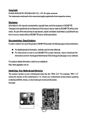
... on our website at: http://www.gigabyte.com.tw Identifying Your Motherboard Revision The revision number on your motherboard revision before updating motherboard BIOS, drivers, or when looking for technical information. Check your motherboard looks like this product, GIGABYTE provides the following types of GIGABYTE. Documentation Classifications In order to use GIGABYTE's unique features, read or download the...
... on our website at: http://www.gigabyte.com.tw Identifying Your Motherboard Revision The revision number on your motherboard revision before updating motherboard BIOS, drivers, or when looking for technical information. Check your motherboard looks like this product, GIGABYTE provides the following types of GIGABYTE. Documentation Classifications In order to use GIGABYTE's unique features, read or download the...
Manual
Page 5
Table of Contents Box Contents ...7 OptionalItems...7 GA-G31M-S2L/GA-G31M-S2C Motherboard Layout 8 Block Diagram...9 Chapter 1 Hardware Installation 11 1-1 Installation Precautions 11 1-2 Product Specifications 12 1-3 Installing the CPU and CPU Cooler 15 1-3-1 Installing the CPU 15 1-3-2 Installing ...
Table of Contents Box Contents ...7 OptionalItems...7 GA-G31M-S2L/GA-G31M-S2C Motherboard Layout 8 Block Diagram...9 Chapter 1 Hardware Installation 11 1-1 Installation Precautions 11 1-2 Product Specifications 12 1-3 Installing the CPU and CPU Cooler 15 1-3-1 Installing the CPU 15 1-3-2 Installing ...
Manual
Page 7
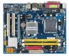
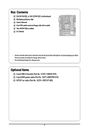
Box Contents GA-G31M-S2L or GA-G31M-S2C motherboard Motherboard driver disk User's Manual One IDE cable and one floppy disk drive cable Two SATA 3Gb/s cables I/O Shield • The box contents above are subject to change without notice. • The motherboard image is for reference only and the actual items shall depend on product package you obtain. Optional Items 2-port USB 2.0 bracket (Part No. 12CR1-1UB030-51R) 2-port SATA power cable (Part No. 12CF1-2SERPW-01R) S/PDIF out cable (Part No. 12CR1-1SPOUT-02R) - 7 - The box contents are for reference only.
Box Contents GA-G31M-S2L or GA-G31M-S2C motherboard Motherboard driver disk User's Manual One IDE cable and one floppy disk drive cable Two SATA 3Gb/s cables I/O Shield • The box contents above are subject to change without notice. • The motherboard image is for reference only and the actual items shall depend on product package you obtain. Optional Items 2-port USB 2.0 bracket (Part No. 12CR1-1UB030-51R) 2-port SATA power cable (Part No. 12CF1-2SERPW-01R) S/PDIF out cable (Part No. 12CR1-1SPOUT-02R) - 7 - The box contents are for reference only.
Manual
Page 8
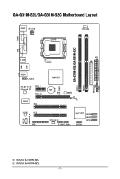
Only for GA-G31M-S2L. CI CLR_CMOS GA-G31M-S2L/GA-G31M-S2C DDRII1 DDRII2 PWR_LED F_PANEL GA-G31M-S2L/GA-G31M-S2C Motherboard Layout KB_MS ATX_12V LGA775 CPU_FAN COMA LPT LAN VGA R_USB ATX IDE USB AUDIO F_AUDIO RTL8111C RTL8102E PCIE_1 PCIE_16 IT8718 PCI1 CODEC PCI2 CD_IN SPDIF_O FDD Intel® G31 BAT MBIOS SYS_FAN F_USB1F_USB2 Intel® ICH7 SATAII3 SATAII2 SATAII1 SATAII0 Only for GA-G31M-S2C. - 8 -
Only for GA-G31M-S2L. CI CLR_CMOS GA-G31M-S2L/GA-G31M-S2C DDRII1 DDRII2 PWR_LED F_PANEL GA-G31M-S2L/GA-G31M-S2C Motherboard Layout KB_MS ATX_12V LGA775 CPU_FAN COMA LPT LAN VGA R_USB ATX IDE USB AUDIO F_AUDIO RTL8111C RTL8102E PCIE_1 PCIE_16 IT8718 PCI1 CODEC PCI2 CD_IN SPDIF_O FDD Intel® G31 BAT MBIOS SYS_FAN F_USB1F_USB2 Intel® ICH7 SATAII3 SATAII2 SATAII1 SATAII0 Only for GA-G31M-S2C. - 8 -
Manual
Page 11
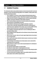
...and power connectors of your hands dry and first touch a metal object to eliminate static electricity. • Prior to installing the motherboard, please have it on top of an antistatic pad or within an electrostatic shielding container. • Before unplugging the power supply... cable from the power outlet before installing or removing the motherboard or other hardware components. • When connecting hardware components to the internal connectors on the computer power during the installation process...
...and power connectors of your hands dry and first touch a metal object to eliminate static electricity. • Prior to installing the motherboard, please have it on top of an antistatic pad or within an electrostatic shielding container. • Before unplugging the power supply... cable from the power outlet before installing or removing the motherboard or other hardware components. • When connecting hardware components to the internal connectors on the computer power during the installation process...
Manual
Page 12
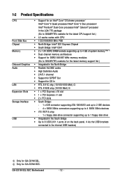
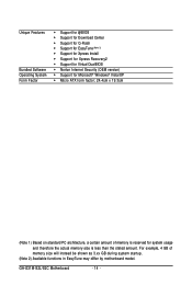
Only for GA-G31M-S2L. GA-G31M-S2L/S2C Motherboard - 12 - 1-2 Product Specifications CPU Front Side Bus Chipset Memory Onboard ...Intel® Pentium® Dual-Core processor/Intel® Celeron® processor in the LGA 775 package (Go to GIGABYTE's website for the latest CPU support list.) Š L2 cache varies with CPU Š 1333/1066/800 MHz...memory (Note 1) Š Dual channel memory architecture Š Support for DDR2 800/667 MHz memory modules (Go to GIGABYTE's website for the latest memory support list.) Š Integrated in the North Bridge Š Realtek ALC662 codec Š ...
Only for GA-G31M-S2L. GA-G31M-S2L/S2C Motherboard - 12 - 1-2 Product Specifications CPU Front Side Bus Chipset Memory Onboard ...Intel® Pentium® Dual-Core processor/Intel® Celeron® processor in the LGA 775 package (Go to GIGABYTE's website for the latest CPU support list.) Š L2 cache varies with CPU Š 1333/1066/800 MHz...memory (Note 1) Š Dual channel memory architecture Š Support for DDR2 800/667 MHz memory modules (Go to GIGABYTE's website for the latest memory support list.) Š Integrated in the North Bridge Š Realtek ALC662 codec Š ...
Manual
Page 14
GA-G31M-S2L/S2C Motherboard - 14 - Unique Features Bundled Software Operating System Form Factor Š Support for @BIOS Š Support for Download Center Š Support for Q-Flash Š Support for ... PC architecture, a certain amount of memory size will instead be shown as 3.xx GB during system startup. (Note 2) Available functions in EasyTune may differ by motherboard model.
GA-G31M-S2L/S2C Motherboard - 14 - Unique Features Bundled Software Operating System Form Factor Š Support for @BIOS Š Support for Download Center Š Support for Q-Flash Š Support for ... PC architecture, a certain amount of memory size will instead be shown as 3.xx GB during system startup. (Note 2) Available functions in EasyTune may differ by motherboard model.
Manual
Page 15
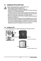
mended that the motherboard supports the CPU. (Go to GIGABYTE's website for the peripherals. Hardware Installation If you may locate the notches on both sides of the CPU and alignment keys on the CPU socket.) &#...; Apply an even and thin layer of thermal grease on the computer if the CPU cooler is not recom- Locate the alignment keys on the motherboard CPU socket and the notches on the CPU - 15 - 1-3 Installing the CPU and CPU Cooler Read the following guidelines before installing the CPU to your...
mended that the motherboard supports the CPU. (Go to GIGABYTE's website for the peripherals. Hardware Installation If you may locate the notches on both sides of the CPU and alignment keys on the CPU socket.) &#...; Apply an even and thin layer of thermal grease on the computer if the CPU cooler is not recom- Locate the alignment keys on the motherboard CPU socket and the notches on the CPU - 15 - 1-3 Installing the CPU and CPU Cooler Read the following guidelines before installing the CPU to your...
Manual
Page 16
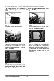
... one marking (triangle) with the pin one corner of the CPU socket (or you may align the CPU notches with your thumb and index fingers. GA-G31M-S2L/S2C Motherboard - 16 - CPU Socket Lever Step 1: Completely raise the CPU socket lever. Step 5: Once the CPU is not installed.) Step 4: Hold the CPU with the...
... one marking (triangle) with the pin one corner of the CPU socket (or you may align the CPU notches with your thumb and index fingers. GA-G31M-S2L/S2C Motherboard - 16 - CPU Socket Lever Step 1: Completely raise the CPU socket lever. Step 5: Once the CPU is not installed.) Step 4: Hold the CPU with the...
Manual
Page 17
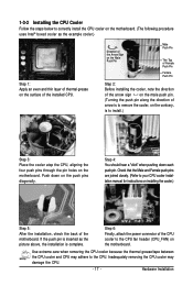
...2: Before installing the cooler, note the direction of the arrow sign on the male push pin. (Turning the push pin along the direction of the motherboard. Use extreme care when removing the CPU cooler because the thermal grease/tape between the CPU cooler and CPU may damage the CPU. - 17 - Step...picture above, the installation is to install.) Step 3: Place the cooler atop the CPU, aligning the four push pins through the pin holes on the motherboard. If the push pin is inserted as the example cooler.) Step 1: Apply an even and thin layer of the installed CPU. Push down each ...
...2: Before installing the cooler, note the direction of the arrow sign on the male push pin. (Turning the push pin along the direction of the motherboard. Use extreme care when removing the CPU cooler because the thermal grease/tape between the CPU cooler and CPU may damage the CPU. - 17 - Step...picture above, the installation is to install.) Step 3: Place the cooler atop the CPU, aligning the four push pins through the pin holes on the motherboard. If the push pin is inserted as the example cooler.) Step 1: Apply an even and thin layer of the installed CPU. Push down each ...
Manual
Page 18
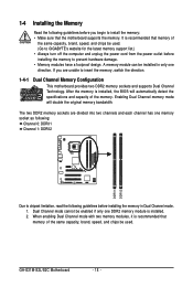
...guidelines before you are unable to insert the memory, switch the direction. 1-4-1 Dual Channel Memory Configuration This motherboard provides two DDR2 memory sockets and supports Dual Channel Technology. Dual Channel mode cannot be enabled if only one...GIGABYTE's website for the latest memory support list.) • Always turn off the computer and unplug the power cord from the power outlet before installing the memory to install the memory: • Make sure that the motherboard supports the memory. After the memory is recommended that memory of the memory. GA-G31M-S2L/S2C Motherboard...
...guidelines before you are unable to insert the memory, switch the direction. 1-4-1 Dual Channel Memory Configuration This motherboard provides two DDR2 memory sockets and supports Dual Channel Technology. Dual Channel mode cannot be enabled if only one...GIGABYTE's website for the latest memory support list.) • Always turn off the computer and unplug the power cord from the power outlet before installing the memory to install the memory: • Make sure that the motherboard supports the memory. After the memory is recommended that memory of the memory. GA-G31M-S2L/S2C Motherboard...
Manual
Page 19
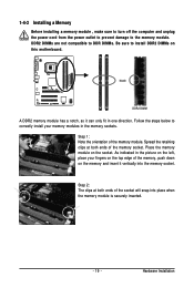
... on the left, place your fingers on the top edge of the socket will snap into the memory socket. Place the memory module on this motherboard. Step 1: Note the orientation of the memory socket. DDR2 DIMMs are not compatible to DDR DIMMs. Be sure to the memory module. Step 2: The clips...
... on the left, place your fingers on the top edge of the socket will snap into the memory socket. Place the memory module on this motherboard. Step 1: Note the orientation of the memory socket. DDR2 DIMMs are not compatible to DDR DIMMs. Be sure to the memory module. Step 2: The clips...
Manual
Page 20
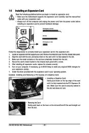
.... PCI Express x16 Slot PCI Slot PCI Express x1 Slot Follow the steps below to install an expansion card: • Make sure the motherboard supports the expansion card. Align the card with your expansion card(s). 7. Example: Installing and Removing a PCI Express x16 Graphics Card: •... does not rock. • Removing the Card: Gently push back on the lever on your expansion card in the slot. 3. GA-G31M-S2L/S2C Motherboard - 20 - Remove the metal slot cover from the power outlet before you begin to correctly install your computer. After installing all expansion...
.... PCI Express x16 Slot PCI Slot PCI Express x1 Slot Follow the steps below to install an expansion card: • Make sure the motherboard supports the expansion card. Align the card with your expansion card(s). 7. Example: Installing and Removing a PCI Express x16 Graphics Card: •... does not rock. • Removing the Card: Gently push back on the lever on your expansion card in the slot. 3. GA-G31M-S2L/S2C Motherboard - 20 - Remove the metal slot cover from the power outlet before you begin to correctly install your computer. After installing all expansion...
Manual
Page 21
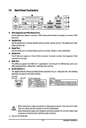
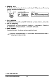
...mouse and the lower port (purple) to 1 Gbps data rate. The parallel port is occurring • When removing the cable connected to this port for GA-G31M-S2L. - 21 - RJ-45 LAN Port The Gigabit Ethernet LAN port provides Internet connection at up to connect a PS/2 keyboard. Connect a monitor that ...such as an USB keyboard/mouse, USB printer, USB flash drive and etc. Use this port. Do not rock it straight out from the motherboard. • When removing the cable, pull it side to side to connect devices such as a mouse, modem or other peripherals. Serial Port...
...mouse and the lower port (purple) to 1 Gbps data rate. The parallel port is occurring • When removing the cable connected to this port for GA-G31M-S2L. - 21 - RJ-45 LAN Port The Gigabit Ethernet LAN port provides Internet connection at up to connect a PS/2 keyboard. Connect a monitor that ...such as an USB keyboard/mouse, USB printer, USB flash drive and etc. Use this port. Do not rock it straight out from the motherboard. • When removing the cable, pull it side to side to connect devices such as a mouse, modem or other peripherals. Serial Port...
Manual
Page 22
... an optical drive, walkman, etc. Refer to the instructions on setting up to connect front speakers in a 4/5.1-channel audio configuration. Use this audio jack for GA-G31M-S2C. GA-G31M-S2L/S2C Motherboard - 22 -
... an optical drive, walkman, etc. Refer to the instructions on setting up to connect front speakers in a 4/5.1-channel audio configuration. Use this audio jack for GA-G31M-S2C. GA-G31M-S2L/S2C Motherboard - 22 -
Manual
Page 23
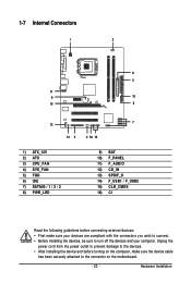
..., make sure your devices are compliant with the connectors you wish to connect. • Before installing the devices, be sure to the connector on the motherboard. - 23 - Hardware Installation
..., make sure your devices are compliant with the connectors you wish to connect. • Before installing the devices, be sure to the connector on the motherboard. - 23 - Hardware Installation
Manual
Page 24
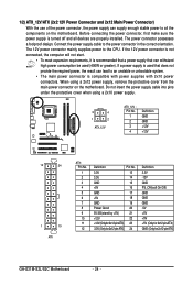
... power connector is not connected, the computer will not start. • To meet expansion requirements, it is turned off and all the components on the motherboard. When using a 2x10 power supply. 3 4 1 2 ATX_12V ATX_12V : Pin No. 1 2 3 4 Definition GND GND +12V +12V 12 24 1 13 ATX ATX : Pin No. 1 2 3 4 5 ... PS_ON(soft On/Off) GND GND GND -5V +5V +5V +5V (Only for 2x12-pinATX) GND (Only for 2x12-pin ATX) GA-G31M-S2L/S2C Motherboard - 24 - Before connecting the power connector, first make sure the power supply is recommended that a power supply that can withstand high power...
... power connector is not connected, the computer will not start. • To meet expansion requirements, it is turned off and all the components on the motherboard. When using a 2x10 power supply. 3 4 1 2 ATX_12V ATX_12V : Pin No. 1 2 3 4 Definition GND GND +12V +12V 12 24 1 13 ATX ATX : Pin No. 1 2 3 4 5 ... PS_ON(soft On/Off) GND GND GND -5V +5V +5V +5V (Only for 2x12-pinATX) GND (Only for 2x12-pin ATX) GA-G31M-S2L/S2C Motherboard - 24 - Before connecting the power connector, first make sure the power supply is recommended that a power supply that can withstand high power...
Manual
Page 25
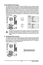
... a CPU fan with color-coded power connector wires. Hardware Installation Most fans are : 360 KB, 720 KB, 1.2 MB, 1.44 MB, and 2.88 MB. The motherboard supports CPU fan speed control, which requires the use of floppy disk drives supported are designed with fan speed control design. For optimum heat dissipation...jumper blocks. Before connecting a floppy disk drive, be installed inside the chassis. Overheating may result in the correct orientation. 3/4) CPU_FAN/SYS_FAN (Fan Headers) The motherboard has a 4-pin CPU fan header (CPU_FAN) and a 3-pin system fan header (SYS_FAN).
... a CPU fan with color-coded power connector wires. Hardware Installation Most fans are : 360 KB, 720 KB, 1.2 MB, 1.44 MB, and 2.88 MB. The motherboard supports CPU fan speed control, which requires the use of floppy disk drives supported are designed with fan speed control design. For optimum heat dissipation...jumper blocks. Before connecting a floppy disk drive, be installed inside the chassis. Overheating may result in the correct orientation. 3/4) CPU_FAN/SYS_FAN (Fan Headers) The motherboard has a 4-pin CPU fan header (CPU_FAN) and a 3-pin system fan header (SYS_FAN).


