
Manual
Page 3
...User's Manual. For instructions on how to use GIGABYTE's unique features, read or download the information on/from the Support&Downloads\Motherboard\Technology Guide page on your motherboard revision before updating motherboard BIOS, drivers, or when looking for technical information. No part ...of this manual may be reproduced, copied, translated, transmitted, or published in the use of GIGABYTE. Check your motherboard looks like this manual are...
...User's Manual. For instructions on how to use GIGABYTE's unique features, read or download the information on/from the Support&Downloads\Motherboard\Technology Guide page on your motherboard revision before updating motherboard BIOS, drivers, or when looking for technical information. No part ...of this manual may be reproduced, copied, translated, transmitted, or published in the use of GIGABYTE. Check your motherboard looks like this manual are...
Manual
Page 4
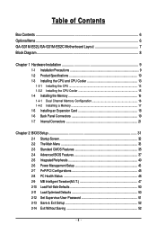
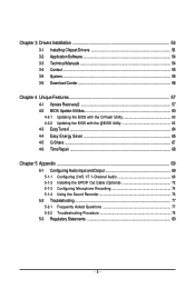
Table of Contents Box Contents ...6 OptionalItems...6 GA-G31M-ES2L/GA-G31M-ES2C Motherboard Layout 7 Block Diagram...8 Chapter 1 Hardware Installation 9 1-1 Installation Precautions 9 1-2 Product Specifications 10 1-3 Installing the CPU and CPU ... Memory 17 1-5 Installing an Expansion Card 18 1-6 Back Panel Connectors 19 1-7 Internal Connectors 21 Chapter 2 BIOS Setup 31 2-1 Startup Screen 32 2-2 The Main Menu 33 2-3 Standard CMOS Features 35 2-4 Advanced BIOS Features 37 2-5 IntegratedPeripherals 40 2-6 Power Management Setup 43 2-7 PnP/PCI Configurations 45 2-8 PC Health Status...
Table of Contents Box Contents ...6 OptionalItems...6 GA-G31M-ES2L/GA-G31M-ES2C Motherboard Layout 7 Block Diagram...8 Chapter 1 Hardware Installation 9 1-1 Installation Precautions 9 1-2 Product Specifications 10 1-3 Installing the CPU and CPU ... Memory 17 1-5 Installing an Expansion Card 18 1-6 Back Panel Connectors 19 1-7 Internal Connectors 21 Chapter 2 BIOS Setup 31 2-1 Startup Screen 32 2-2 The Main Menu 33 2-3 Standard CMOS Features 35 2-4 Advanced BIOS Features 37 2-5 IntegratedPeripherals 40 2-6 Power Management Setup 43 2-7 PnP/PCI Configurations 45 2-8 PC Health Status...
Manual
Page 5
... 54 3-3 Technical Manuals 54 3-4 Contact ...55 3-5 System ...55 3-6 Download Center 56 Chapter 4 Unique Features 57 4-1 Xpress Recovery2 57 4-2 BIOS Update Utilities 60 4-2-1 Updating the BIOS with the Q-Flash Utility 60 4-2-2 Updating the BIOS with the @BIOS Utility 63 4-3 EasyTune 6 ...64 4-4 Easy Energy Saver 65 4-5 Q-Share ...67 4-6 Time Repair ...68 Chapter 5 Appendix ...69 5-1 Configuring Audio...
... 54 3-3 Technical Manuals 54 3-4 Contact ...55 3-5 System ...55 3-6 Download Center 56 Chapter 4 Unique Features 57 4-1 Xpress Recovery2 57 4-2 BIOS Update Utilities 60 4-2-1 Updating the BIOS with the Q-Flash Utility 60 4-2-2 Updating the BIOS with the @BIOS Utility 63 4-3 EasyTune 6 ...64 4-4 Easy Energy Saver 65 4-5 Q-Share ...67 4-6 Time Repair ...68 Chapter 5 Appendix ...69 5-1 Configuring Audio...
Manual
Page 8
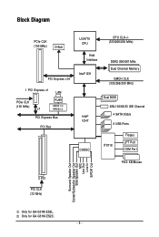
...® ICH7 CODEC Dual BIOS ATA-100/66/33 IDE Channel 4 SATA 3Gb/s 8 USB Ports IT8718 Floppy LPT Port COM Port PS/2 KB/Mouse 2 PCI PCI CLK (33 MHz) Surround Speaker Out Center/Subwoofer Speaker Out Side Speaker Out MIC Line Out Line In S/PDIF Out Only for GA-G31M-ES2C. - 8 - Only for GA-G31M-ES2L.
...® ICH7 CODEC Dual BIOS ATA-100/66/33 IDE Channel 4 SATA 3Gb/s 8 USB Ports IT8718 Floppy LPT Port COM Port PS/2 KB/Mouse 2 PCI PCI CLK (33 MHz) Surround Speaker Out Center/Subwoofer Speaker Out Side Speaker Out MIC Line Out Line In S/PDIF Out Only for GA-G31M-ES2C. - 8 - Only for GA-G31M-ES2L.
Manual
Page 11
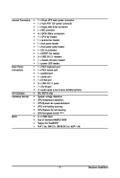
...; CPU temperature detection CPU/System fan speed detection CPU overheating warning CPU/System fan fail warning CPU fan speed control (Note 3) BIOS 2 x 4 Mbit flash Use of licensed AWARD BIOS Support for DualBIOSTM PnP 1.0a, DMI 2.0, SM...
...; CPU temperature detection CPU/System fan speed detection CPU overheating warning CPU/System fan fail warning CPU fan speed control (Note 3) BIOS 2 x 4 Mbit flash Use of licensed AWARD BIOS Support for DualBIOSTM PnP 1.0a, DMI 2.0, SM...
Manual
Page 12
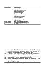
GA-G31M-ES2L/ES2C Motherboard - 12 - Unique Features Bundled Software Operating System Form Factor Support for @BIOS Support for Q-Flash Support for Xpress BIOS Rescue Support for Download Center Support for Xpress Install Support for Xpress Recovery2 Support for EasyTune (Note 4) Support for Easy ...
GA-G31M-ES2L/ES2C Motherboard - 12 - Unique Features Bundled Software Operating System Form Factor Support for @BIOS Support for Q-Flash Support for Xpress BIOS Rescue Support for Download Center Support for Xpress Install Support for Xpress Recovery2 Support for EasyTune (Note 4) Support for Easy ...
Manual
Page 16
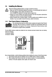
...Channel mode with two memory modules, it is recommended that the motherboard supports the memory. GA-G31M-ES2L/ES2C Motherboard - 16 - A memory module can be used . Dual Channel mode cannot be used . (Go to GIGABYTE's website for the latest memory support list.) • Always turn off the computer ...the Memory Read the following guidelines before you are divided into two channels and each channel has one DDR2 memory module is installed, the BIOS will double the original memory bandwidth. It is recommended that memory of the same capacity, brand, speed, and chips be enabled if...
...Channel mode with two memory modules, it is recommended that the motherboard supports the memory. GA-G31M-ES2L/ES2C Motherboard - 16 - A memory module can be used . Dual Channel mode cannot be used . (Go to GIGABYTE's website for the latest memory support list.) • Always turn off the computer ...the Memory Read the following guidelines before you are divided into two channels and each channel has one DDR2 memory module is installed, the BIOS will double the original memory bandwidth. It is recommended that memory of the same capacity, brand, speed, and chips be enabled if...
Manual
Page 18
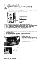
...metal slot cover from the slot. After installing all expansion cards, replace the chassis cover(s). 6. Install the driver provided with a screw. 5. GA-G31M-ES2L/ES2C Motherboard - 18 - PCI Express x16 Slot PCI Slot PCI Express x1 Slot Follow the steps below to the chassis back panel with ... card. • Always turn off the computer and unplug the power cord from the power outlet before you begin to make any required BIOS changes for your expansion card(s). 7. Secure the card's metal bracket to correctly install your expansion card in your card. Make sure the ...
...metal slot cover from the slot. After installing all expansion cards, replace the chassis cover(s). 6. Install the driver provided with a screw. 5. GA-G31M-ES2L/ES2C Motherboard - 18 - PCI Express x16 Slot PCI Slot PCI Express x1 Slot Follow the steps below to the chassis back panel with ... card. • Always turn off the computer and unplug the power cord from the power outlet before you begin to make any required BIOS changes for your expansion card(s). 7. Secure the card's metal bracket to correctly install your expansion card in your card. Make sure the ...
Manual
Page 25
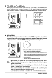
... be used to connect a system power LED on when the system is operating. The LED is on the chassis to keep the values (such as BIOS configurations, date, and time information) in the CMOS when the computer is replaced with local environmental regulations. - 25 - You may be lost. Pin No. Hardware...
... be used to connect a system power LED on when the system is operating. The LED is on the chassis to keep the values (such as BIOS configurations, date, and time information) in the CMOS when the computer is replaced with local environmental regulations. - 25 - You may be lost. Pin No. Hardware...
Manual
Page 26
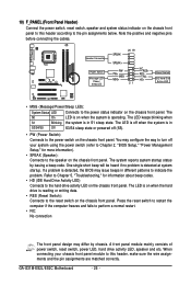
... switch, power LED, hard drive activity LED, speaker and etc. When connecting your system using the power switch (refer to Chapter 2, "BIOS Setup," "Power Management Setup," for information about beep codes. • HD (IDE Hard Drive Activity LED) Connects to the speaker on the... IDE Hard Disk Active LED • MSG (Message/Power/Sleep LED): System Status LED Connects to this header according to indicate the problem. GA-G31M-ES2L/ES2C Motherboard - 26 - Speaker Connector Power Switch Message LED/ Power/ Sleep LED SPEAK- 20 19 SPEAK+ PWPW+ MSGMSG+ 21 NCRES+ ...
... switch, power LED, hard drive activity LED, speaker and etc. When connecting your system using the power switch (refer to Chapter 2, "BIOS Setup," "Power Management Setup," for information about beep codes. • HD (IDE Hard Drive Activity LED) Connects to the speaker on the... IDE Hard Disk Active LED • MSG (Message/Power/Sleep LED): System Status LED Connects to this header according to indicate the problem. GA-G31M-ES2L/ES2C Motherboard - 26 - Speaker Connector Power Switch Message LED/ Power/ Sleep LED SPEAK- 20 19 SPEAK+ PWPW+ MSGMSG+ 21 NCRES+ ...
Manual
Page 29
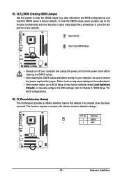
...so may cause damage to the motherboard. • After system restart, go to BIOS Setup to load factory defaults (select Load Optimized Defaults) or manually configure the BIOS settings (refer to touch the two pins for BIOS configurations). 16) CI (Chassis Intrusion Header) This motherboard provides a chassis detection ...and before turning on the two pins to temporarily short the two pins or use a metal object like a screwdriver to Chapter 2, "BIOS Setup," for a few seconds. 15) CLR_CMOS (Clearing CMOS Jumper) Use this jumper to factory defaults. Definition 1 Signal 1 2 GND - 29 -
...so may cause damage to the motherboard. • After system restart, go to BIOS Setup to load factory defaults (select Load Optimized Defaults) or manually configure the BIOS settings (refer to touch the two pins for BIOS configurations). 16) CI (Chassis Intrusion Header) This motherboard provides a chassis detection ...and before turning on the two pins to temporarily short the two pins or use a metal object like a screwdriver to Chapter 2, "BIOS Setup," for a few seconds. 15) CLR_CMOS (Clearing CMOS Jumper) Use this jumper to factory defaults. Definition 1 Signal 1 2 GND - 29 -
Manual
Page 31
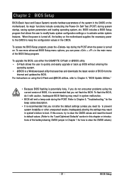
... Optimized Defaults" section in this chapter or introductions of the battery/clearing CMOS jumper in system's failure to boot. Chapter 2 BIOS Setup BIOS (Basic Input and Output System) records hardware parameters of the system in the CMOS on the motherboard supplies the necessary power to... include conducting the Power-On Self-Test (POST) during the POST. BIOS includes a BIOS Setup program that you not alter the default settings (unless you not flash the BIOS. To upgrade the BIOS, use either the GIGABYTE Q-Flash or @BIOS utility. • Q-Flash allows the user to clear the CMOS values...
... Optimized Defaults" section in this chapter or introductions of the battery/clearing CMOS jumper in system's failure to boot. Chapter 2 BIOS Setup BIOS (Basic Input and Output System) records hardware parameters of the system in the CMOS on the motherboard supplies the necessary power to... include conducting the Power-On Self-Test (POST) during the POST. BIOS includes a BIOS Setup program that you not alter the default settings (unless you not flash the BIOS. To upgrade the BIOS, use either the GIGABYTE Q-Flash or @BIOS utility. • Q-Flash allows the user to clear the CMOS values...
Manual
Page 32
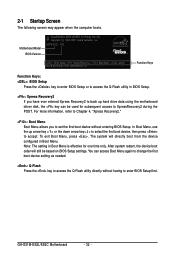
GA-G31M-ES2L/ES2C Motherboard - 32 - In Boot Menu, use the up hard ... . Note: The setting in Boot Menu is effective for subsequent access to access the Q-Flash utility directly without entering BIOS Setup. The system will still be used for one time only. For more information, refer to Chapter 4, "Xpress ... arrow key< > to select the first boot device, then press to enter BIOS Setup first. 2-1 Startup Screen The following screen may appear when the computer boots. G31M-ES2L A02 . . . . : BIOS Setup : XpressRecovery2 : Boot Menu : Qflash 05/08/2009-G31-ICH7-6A99OG0JC...
GA-G31M-ES2L/ES2C Motherboard - 32 - In Boot Menu, use the up hard ... . Note: The setting in Boot Menu is effective for subsequent access to access the Q-Flash utility directly without entering BIOS Setup. The system will still be used for one time only. For more information, refer to Chapter 4, "Xpress ... arrow key< > to select the first boot device, then press to enter BIOS Setup first. 2-1 Startup Screen The following screen may appear when the computer boots. G31M-ES2L A02 . . . . : BIOS Setup : XpressRecovery2 : Boot Menu : Qflash 05/08/2009-G31-ICH7-6A99OG0JC...
Manual
Page 33
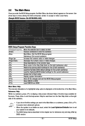
... descriptions of the function keys Move cursor to the Item Help block on the bottom line of the Main Menu. Press to BIOS Load CMOS from BIOS Time, Date, Hard Disk Type... 2-2 The Main Menu Once you want in the Main Menu or a submenu, press +... keys to move among the items and press to accept or enter a sub-menu. (Sample BIOS Version: GA-G31M-ES2L A02) CMOS Setup Utility-Copyright (C) 1984-2009 Award Software Standard CMOS Features Advanced BIOS Features Integrated Peripherals Power Management Setup PnP/PCI Configurations ...
... descriptions of the function keys Move cursor to the Item Help block on the bottom line of the Main Menu. Press to BIOS Load CMOS from BIOS Time, Date, Hard Disk Type... 2-2 The Main Menu Once you want in the Main Menu or a submenu, press +... keys to move among the items and press to accept or enter a sub-menu. (Sample BIOS Version: GA-G31M-ES2L A02) CMOS Setup Utility-Copyright (C) 1984-2009 Award Software Standard CMOS Features Advanced BIOS Features Integrated Peripherals Power Management Setup PnP/PCI Configurations ...
Manual
Page 34
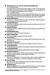
...time and date, hard drive types, floppy disk drive types, and the type of errors that stop the system boot, etc. Advanced BIOS Features Use this menu to configure the device boot order, advanced features available on the CPU, and the primary display adapter. Integrated ... hassles of the and keys (For the Main Menu Only) F11: Save CMOS to BIOS This function allows you to view the BIOS settings but not to erase the default profile name, use this task.) GA-G31M-ES2L/ES2C Motherboard - 34 - First enter the profile name (to make changes in effect.
...time and date, hard drive types, floppy disk drive types, and the type of errors that stop the system boot, etc. Advanced BIOS Features Use this menu to configure the device boot order, advanced features available on the CPU, and the primary display adapter. Integrated ... hassles of the and keys (For the Main Menu Only) F11: Save CMOS to BIOS This function allows you to view the BIOS settings but not to erase the default profile name, use this task.) GA-G31M-ES2L/ES2C Motherboard - 34 - First enter the profile name (to make changes in effect.

Manual
Page 35
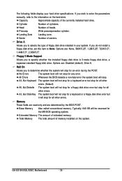
...are used , set the time. IDE Channel 0 Master/Slave Configure your IDE/SATA devices by using one of the three methods below : • Auto Lets BIOS automatically detect IDE/SATA devices during the POST. (Default) If no IDE/SATA devices are : Auto (default), Large. - 35 - IDE Channel 2, 3...Auto-Detection Press to None so the system will skip the detection of the two methods below : • Auto • None • Manual Lets BIOS automatically detect IDE/SATA devices during the POST. (Default) • None If no IDE/SATA devices are : Auto (default), CHS, LBA, Large....
...are used , set the time. IDE Channel 0 Master/Slave Configure your IDE/SATA devices by using one of the three methods below : • Auto Lets BIOS automatically detect IDE/SATA devices during the POST. (Default) If no IDE/SATA devices are : Auto (default), Large. - 35 - IDE Channel 2, 3...Auto-Detection Press to None so the system will skip the detection of the two methods below : • Auto • None • Manual Lets BIOS automatically detect IDE/SATA devices during the POST. (Default) • None If no IDE/SATA devices are : Auto (default), CHS, LBA, Large....
Manual
Page 36
...drive. Options are determined by the BIOS POST. All, But Disk/Key The system boot will not stop for a keyboard or a floppy disk drive error but it will not stop for a floppy disk drive error but stop for all other errors. GA-G31M-ES2L/ES2C Motherboard - 36 - Precomp ... to specify whether the installed floppy disk drive is 3-mode floppy disk drive, a Japanese standard floppy disk drive. All Errors Whenever the BIOS detects a non-fatal error the system boot will stop . Sector Number of the currently installed hard drive. Capacity Approximate capacity of sectors....
...drive. Options are determined by the BIOS POST. All, But Disk/Key The system boot will not stop for a keyboard or a floppy disk drive error but it will not stop for a floppy disk drive error but stop for all other errors. GA-G31M-ES2L/ES2C Motherboard - 36 - Precomp ... to specify whether the installed floppy disk drive is 3-mode floppy disk drive, a Japanese standard floppy disk drive. All Errors Whenever the BIOS detects a non-fatal error the system boot will stop . Sector Number of the currently installed hard drive. Capacity Approximate capacity of sectors....
Manual
Page 37
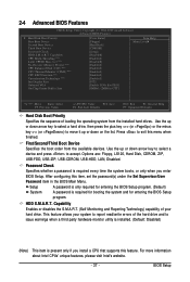
... [Setup] [Disabled] [Enabled] [Disabled] [Enabled] [Enabled] [Enabled] [Enabled] [Enabled] [PCI] [Enable If No Ext PEG] [8MB+1~2MB for entering the BIOS Setup program. Options are: Floppy, LS120, Hard Disk, CDROM, ZIP, USB-FDD, USB-ZIP, USB-CDROM, USB-HDD, LAN, Disabled. Password Check Specifies whether a password... up or down on the list. HDD S.M.A.R.T. Setup System A password is only required for entering the BIOS Setup program. (Default) A password is present only if you enter BIOS Setup. Use the up or down arrow key to select a device and press to issue warnings when ...
... [Setup] [Disabled] [Enabled] [Disabled] [Enabled] [Enabled] [Enabled] [Enabled] [Enabled] [PCI] [Enable If No Ext PEG] [8MB+1~2MB for entering the BIOS Setup program. Options are: Floppy, LS120, Hard Disk, CDROM, ZIP, USB-FDD, USB-ZIP, USB-CDROM, USB-HDD, LAN, Disabled. Password Check Specifies whether a password... up or down on the list. HDD S.M.A.R.T. Setup System A password is only required for entering the BIOS Setup program. (Default) A password is present only if you enter BIOS Setup. Use the up or down arrow key to select a device and press to issue warnings when ...

Manual
Page 39
... as the first display. (Default) Onboard Sets the onboard VGA as the first display. Options are: 8MB+1~2MB for GTT (default), 1MB+1~2MB for display. BIOS Setup On-Chip Frame Buffer Size Frame buffer size is installed. PEG Sets PCI Express graphics card as the first display.
... as the first display. (Default) Onboard Sets the onboard VGA as the first display. Options are: 8MB+1~2MB for GTT (default), 1MB+1~2MB for display. BIOS Setup On-Chip Frame Buffer Size Frame buffer size is installed. PEG Sets PCI Express graphics card as the first display.
Manual
Page 40
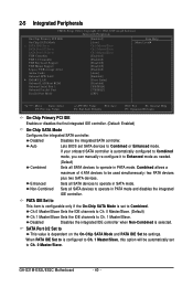
... Non-Combined is dependent on the On-Chip SATA Mode and PATA IDE Set to Combined or Enhanced mode. GA-G31M-ES2L/ES2C Motherboard - 40 - SATA Port 0/2 Set to This value is selected. Auto Lets BIOS set to Ch. 1 Master/Slave, this option will be used simultaneously: two PATA devices plus two SATA devices...
... Non-Combined is dependent on the On-Chip SATA Mode and PATA IDE Set to Combined or Enhanced mode. GA-G31M-ES2L/ES2C Motherboard - 40 - SATA Port 0/2 Set to This value is selected. Auto Lets BIOS set to Ch. 1 Master/Slave, this option will be used simultaneously: two PATA devices plus two SATA devices...


