Manual
Page 4
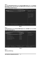
... submenu, select the model of the SATA hard drive onto which you intent to exit this menu. to move it up, or to 3 No-Execute Memory Protect CPU Enhanced Halt (C1E) CPU Thermal Monitor 2(TM2) CPU EIST Function (µù) [Press Enter] [CDROM] [Hard Disk] [CDROM] [Setup] [Enabled] [Disabled] [Enabled] [Enabled...
... submenu, select the model of the SATA hard drive onto which you intent to exit this menu. to move it up, or to 3 No-Execute Memory Protect CPU Enhanced Halt (C1E) CPU Thermal Monitor 2(TM2) CPU EIST Function (µù) [Press Enter] [CDROM] [Hard Disk] [CDROM] [Setup] [Enabled] [Disabled] [Enabled] [Enabled...
Manual
Page 5
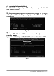
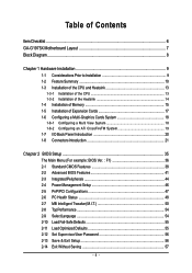
... option ROM V5.0.0.1032 ICH7R wRAID5 Copyright(C) 2003-05 Intel Corporation. Press CTRL+ I , the Create RAID Volume screen will appear (Figure 5). Step 1: After the POST memory test begins and before the operating system boot begins, look for a message which says "Press to Non-RAID 4. Delete RAID Volume 3. All Rights Reversed. All...
... option ROM V5.0.0.1032 ICH7R wRAID5 Copyright(C) 2003-05 Intel Corporation. Press CTRL+ I , the Create RAID Volume screen will appear (Figure 5). Step 1: After the POST memory test begins and before the operating system boot begins, look for a message which says "Press to Non-RAID 4. Delete RAID Volume 3. All Rights Reversed. All...
Manual
Page 4
Table of Contents ItemChecklist ...6 GA-G1975X Motherboard Layout 7 Block Diagram ...8 Chapter 1 Hardware Installation 9 1-1 Considerations Prior to Installation 9 1-2 Feature Summary 10 1-3 Installation of the CPU and Heatsink 13 1-3-1 Installation of the CPU 13 1-3-2 Installation of the Heatsink 14 1-4 Installation of Memory 15 1-5 Installation of Expansion Cards 17 1-6 Configuring a Multi-Graphics Cards System 18 1-6-1 Configuring a Multi...
Table of Contents ItemChecklist ...6 GA-G1975X Motherboard Layout 7 Block Diagram ...8 Chapter 1 Hardware Installation 9 1-1 Considerations Prior to Installation 9 1-2 Feature Summary 10 1-3 Installation of the CPU and Heatsink 13 1-3-1 Installation of the CPU 13 1-3-2 Installation of the Heatsink 14 1-4 Installation of Memory 15 1-5 Installation of Expansion Cards 17 1-6 Configuring a Multi-Graphics Cards System 18 1-6-1 Configuring a Multi...
Manual
Page 8
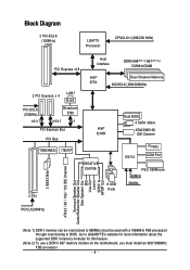
...) LGA775 Processor CPUCLK+/-(266/200 MHz) PCI Express x16 Host Interface DDRII 888(Note 1)/ 667 (Note 2)/ 533MHz DIMM Intel® 975X Dual Channel Memory MCHCLK (266/200MHz) 2 PCI Express x 4 LAN1 RJ45 PCI-ECLK (100MHz) x4/x1 Broadcom 5789 x4/x1 x1 PCI Express Bus PCI Bus TSB43AB23...MIC Line-Out Line-In SPDIF In SPDIF Out (Note 1) DDR II memory can be overclocked to GIGABYTE's website for more information about the supported DDR II memory modules for this feature. (Note 2) To use a DDR II 667 memory module on the motherboard, you must be used with a 1066MHz FSB processor...
...) LGA775 Processor CPUCLK+/-(266/200 MHz) PCI Express x16 Host Interface DDRII 888(Note 1)/ 667 (Note 2)/ 533MHz DIMM Intel® 975X Dual Channel Memory MCHCLK (266/200MHz) 2 PCI Express x 4 LAN1 RJ45 PCI-ECLK (100MHz) x4/x1 Broadcom 5789 x4/x1 x1 PCI Express Bus PCI Bus TSB43AB23...MIC Line-Out Line-In SPDIF In SPDIF Out (Note 1) DDR II memory can be overclocked to GIGABYTE's website for more information about the supported DDR II memory modules for this feature. (Note 2) To use a DDR II 667 memory module on the motherboard, you must be used with a 1066MHz FSB processor...

Manual
Page 10
... ECC/non-ECC type DRAM Š 2 PCI Express x 16 slot Š 2 PCI Express x 4 slots Š 2 PCI slots GA-G1975X Motherboard - 10 - English 1-2 Feature Summary CPU Front Side Bus Chipset LAN Audio IEEE 1394 Storage O.S Support Memory Expanstion Slots Š Supports LGA775 Intel® Pentium® Processor Extreme Edition/ Pentium® D / Pentium® 4 (Note...
... ECC/non-ECC type DRAM Š 2 PCI Express x 16 slot Š 2 PCI Express x 4 slots Š 2 PCI slots GA-G1975X Motherboard - 10 - English 1-2 Feature Summary CPU Front Side Bus Chipset LAN Audio IEEE 1394 Storage O.S Support Memory Expanstion Slots Š Supports LGA775 Intel® Pentium® Processor Extreme Edition/ Pentium® D / Pentium® 4 (Note...
Manual
Page 12
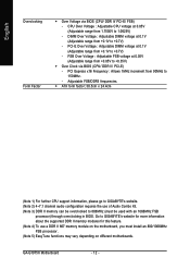
... 24.4cm (Note 1) For further CPU support information, please go to GIGABYTE's website. (Note 2) 4~7.1 channel audio configuration requires the use a DDR II 667 memory module on different motherboards. PCI-E Over Voltage : Adjustable DIMM voltage at...GIGABYTE's website for more information about the supported DDR II memory modules for this feature. (Note 4) To use of Audio Combo Kit. (Note 3) DDR II memory can be used with an 1066MHz FSB processor) through overclocking in BIOS. FSB Over Voltage : Adjustable FSB voltage at 0.1V (Adjustable range from +0.05V to 1.0625V) - GA-G1975X...
... 24.4cm (Note 1) For further CPU support information, please go to GIGABYTE's website. (Note 2) 4~7.1 channel audio configuration requires the use a DDR II 667 memory module on different motherboards. PCI-E Over Voltage : Adjustable DIMM voltage at...GIGABYTE's website for more information about the supported DDR II memory modules for this feature. (Note 4) To use of Audio Combo Kit. (Note 3) DDR II memory can be used with an 1066MHz FSB processor) through overclocking in BIOS. FSB Over Voltage : Adjustable FSB voltage at 0.1V (Adjustable range from +0.05V to 1.0625V) - GA-G1975X...
Manual
Page 13
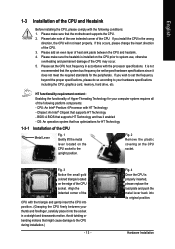
... that might cause damage to system use, otherwise overheating and permanent damage of heat sink paste between your hardware specifications including the CPU, graphics card, memory, hard drive, etc. BIOS: A BIOS that has optimizations for the peripherals. English 1-3 Installation of the following conditions: 1. Please add an even layer of the CPU...
... that might cause damage to system use, otherwise overheating and permanent damage of heat sink paste between your hardware specifications including the CPU, graphics card, memory, hard drive, etc. BIOS: A BIOS that has optimizations for the peripherals. English 1-3 Installation of the following conditions: 1. Please add an even layer of the CPU...
Manual
Page 15
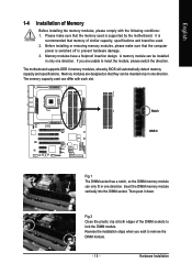
... computer power is recommended that they can be used is supported by the motherboard. Reverse the installation steps when you are designed so that memory of similar capacity, specifications and brand be installed in one direction. Notch DDR II Fig.1 The DIMM socket has a notch, so the DIMM... memory module can differ with the following conditions: 1. If you wish to insert the module, please switch the direction. Then push it down. Fig.2 Close ...
... computer power is recommended that they can be used is supported by the motherboard. Reverse the installation steps when you are designed so that memory of similar capacity, specifications and brand be installed in one direction. Notch DDR II Fig.1 The DIMM socket has a notch, so the DIMM... memory module can differ with the following conditions: 1. If you wish to insert the module, please switch the direction. Then push it down. Fig.2 Close ...
Manual
Page 16
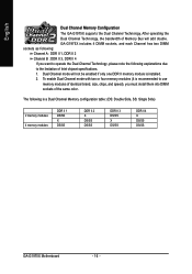
... (it is installed. 2. Dual Channel mode will add double. English Dual Channel Memory Configuration The GA-G1975X supports the Dual Channel Technology. GA-G1975X includes 4 DIMM sockets, and each Channel has two DIMM sockets as following: Channel A : DDR II 1, DDR II 2 Channel B : DDR II 3, DDR II 4...please note the following is a Dual Channel Memory configuration table: (DS: Double Side, SS: Single Side) 2 memory modules 4 memory modules DDR II 1 DS/SS X DS/SS DDR II 2 X DS/SS DS/SS DDR II 3 DS/SS X DS/SS DDR II 4 X DS/SS DS/SS GA-G1975X Motherboard - 16 - After operating the Dual...
... (it is installed. 2. Dual Channel mode will add double. English Dual Channel Memory Configuration The GA-G1975X supports the Dual Channel Technology. GA-G1975X includes 4 DIMM sockets, and each Channel has two DIMM sockets as following: Channel A : DDR II 1, DDR II 2 Channel B : DDR II 3, DDR II 4...please note the following is a Dual Channel Memory configuration table: (DS: Double Side, SS: Single Side) 2 memory modules 4 memory modules DDR II 1 DS/SS X DS/SS DDR II 2 X DS/SS DS/SS DDR II 3 DS/SS X DS/SS DDR II 4 X DS/SS DS/SS GA-G1975X Motherboard - 16 - After operating the Dual...
Manual
Page 38
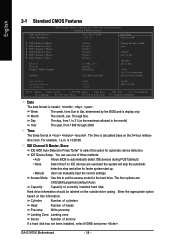
...not been installed, select NONE and press . Week Month The week, from 1999 through 2098 Time The times format in the month) Base Memory Extended Memory Total Memory 640K 511M 512M KLJI: Move Enter: Select +/-/PU/PD: Value F10: Save F3: Language F5: Previous Values F6: Fail-Safe Defaults.... Jan. For example, 1 p.m. The four options are used and the system will skip the automatic detection step and allow for the hard drive. GA-G1975X Motherboard - 38 - Through Dec. The time is 13:00:00. is calculated base on the outside drive casing. IDE Channel 0 Master, Slave ...
...not been installed, select NONE and press . Week Month The week, from 1999 through 2098 Time The times format in the month) Base Memory Extended Memory Total Memory 640K 511M 512M KLJI: Move Enter: Select +/-/PU/PD: Value F10: Save F3: Language F5: Previous Values F6: Fail-Safe Defaults.... Jan. For example, 1 p.m. The four options are used and the system will skip the automatic detection step and allow for the hard drive. GA-G1975X Motherboard - 38 - Through Dec. The time is 13:00:00. is calculated base on the outside drive casing. IDE Channel 0 Master, Slave ...

Manual
Page 40
..., or 640K for systems with 640K or more memory installed on the motherboard. Total Memory This item displays the memory size that used. This is the amount of the BIOS. The value of base (or conventional) memory installed in the CPU's memory address map. GA-G1975X Motherboard - 40 - Base Memory The POST of the BIOS will determine the...
..., or 640K for systems with 640K or more memory installed on the motherboard. Total Memory This item displays the memory size that used. This is the amount of the BIOS. The value of base (or conventional) memory installed in the CPU's memory address map. GA-G1975X Motherboard - 40 - Base Memory The POST of the BIOS will determine the...
Manual
Page 41
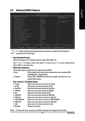
... sequence for onboard(or add-on cards) SCSI, RAID, etc. Press to exit this function. (Note) This item will show up , or to 3 No-Execute Memory Protect (Note) CPU Enhanced Halt (C1E) (Note) CPU Thermal Monitor 2(TM2) (Note) CPU EIST Function (Note) Virtualization Technology Delay For HDD (Secs) Init Display First...
... sequence for onboard(or add-on cards) SCSI, RAID, etc. Press to exit this function. (Note) This item will show up , or to 3 No-Execute Memory Protect (Note) CPU Enhanced Halt (C1E) (Note) CPU Thermal Monitor 2(TM2) (Note) CPU EIST Function (Note) Virtualization Technology Delay For HDD (Secs) Init Display First...

Manual
Page 43
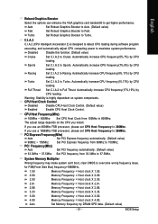
... HDD time from which card when you to select the first initiation of the monitor display from 0~15(secs). DRAM Data Integrity Mode ECC Enable Memory Error Checking and Correction feature when all installed DIMMs are 72bits width. CPU Thermal Monitor 2 (TM2) (Note) Enabled Disabled Enable CPU Thermal Monitor ...Enabled Disabled Limit CPUID Maximum value to PCI Express VGA card (PCIE_16_2 slot). Disables CPUID Limit for windows XP.(Default value) No-Execute Memory Protect (Note) Enabled Enable No-Execute Memory Protect function.(Default value) Disabled Disable No-Execute...
... HDD time from which card when you to select the first initiation of the monitor display from 0~15(secs). DRAM Data Integrity Mode ECC Enable Memory Error Checking and Correction feature when all installed DIMMs are 72bits width. CPU Thermal Monitor 2 (TM2) (Note) Enabled Disabled Enable CPU Thermal Monitor ...Enabled Disabled Limit CPUID Maximum value to PCI Express VGA card (PCIE_16_2 slot). Disables CPUID Limit for windows XP.(Default value) No-Execute Memory Protect (Note) Enabled Enable No-Execute Memory Protect function.(Default value) Disabled Disable No-Execute...
Manual
Page 47
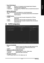
Disabled Keyboard 98 Disabled this function. (Default value) If your keyboard have "POWER Key" button, you can press the key to power on the system. Memory When AC-power back to the system, the system will be in "On" state. Enter Input password (from 1 to 5 characters to set the Keyboard Power ...
Disabled Keyboard 98 Disabled this function. (Default value) If your keyboard have "POWER Key" button, you can press the key to power on the system. Memory When AC-power back to the system, the system will be in "On" state. Enter Input password (from 1 to 5 characters to set the Keyboard Power ...
Manual
Page 50
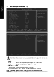
... (Note) Robust Graphics Booster C.I.A. 2 CPU Host Clock Control x CPU Host Frequency(Mhz) x PCI Express Frequency(Mhz) x PCI Frequency(Mhz) System Memory Multiplier Memory Frequency (Mhz) DIMM OverVoltage Control PCI-E OverVoltage Control FSB OverVoltage Control CPU Voltage Control Normal CPU Vcore [High] [16X] [Auto] [Disabled] [Disabled...er Set Clock Ratio For Frequency-locked CPU CAS Latency Time DRAM RAS# to CAS# Delay DRAM RAS# Precharge Active to Low. GA-G1975X Motherboard - 50 - CPU Clock Ratio (Note) This setup option will show up when you install a processor that supports this ...
... (Note) Robust Graphics Booster C.I.A. 2 CPU Host Clock Control x CPU Host Frequency(Mhz) x PCI Express Frequency(Mhz) x PCI Frequency(Mhz) System Memory Multiplier Memory Frequency (Mhz) DIMM OverVoltage Control PCI-E OverVoltage Control FSB OverVoltage Control CPU Voltage Control Normal CPU Vcore [High] [16X] [Auto] [Disabled] [Disabled...er Set Clock Ratio For Frequency-locked CPU CAS Latency Time DRAM RAS# to CAS# Delay DRAM RAS# Precharge Active to Low. GA-G1975X Motherboard - 50 - CPU Clock Ratio (Note) This setup option will show up when you install a processor that supports this ...
Manual
Page 51
... Frequency to Turbo. Disabled Disable this function. (Default value) Cruise Set C.I .A.2 to Fast. Sports Set C.I .A.2 to 266Mhz. Turbo Set C.I .A.2 to Cruise. If you install. System Memory Multiplier Wrong frequency may make system can enhance the VGA graphics card bandwidth to Full Thrust. CPU Host Frequency(Mhz) 100Mhz ~ 600Mhz Set CPU Host...
... Frequency to Turbo. Disabled Disable this function. (Default value) Cruise Set C.I .A.2 to Fast. Sports Set C.I .A.2 to 266Mhz. Turbo Set C.I .A.2 to Cruise. If you install. System Memory Multiplier Wrong frequency may make system can enhance the VGA graphics card bandwidth to Full Thrust. CPU Host Frequency(Mhz) 100Mhz ~ 600Mhz Set CPU Host...

Manual
Page 53
...) Active to Precharge Delay This feature allows you to set Active to set the delay time that you use . Vendor \ Brand Select the memory module that you to select the CAS latency Time, When any DDRII DIMM installed. 4~15 Set active to 10%. Set active to Refresh mode... timing is designed especially to maximize memory performance and boost memory bandwidth up to Precharge delay timing is 7.8 usec. Set active to 6. English CAS Latency Time This feature allows you use . Auto...
...) Active to Precharge Delay This feature allows you to set Active to set the delay time that you use . Vendor \ Brand Select the memory module that you to select the CAS latency Time, When any DDRII DIMM installed. 4~15 Set active to 10%. Set active to Refresh mode... timing is designed especially to maximize memory performance and boost memory bandwidth up to Precharge delay timing is 7.8 usec. Set active to 6. English CAS Latency Time This feature allows you use . Auto...
Manual
Page 63
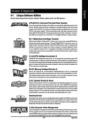
.... Download Center Download Center allows users to allow for download. Designed to enabled Gigabyte's unique C.I.A. 2 and M.I .B. 2) is designed especially to maximize memory performance and boost memory bandwidth up the PC chassis and short-circuit the "Clear CMOS" pins or ...execution of programs. When the function is disabled, the CPU is returned to optimize memory performance by selecting from system over-enhancement by the user. C.I.A.2 (CPU Intelligent Accelerator 2) GIGABYTE CPU Intelligent Accelerator 2(C.I .T. Instead, S.O.S. English Chapter 4 Appendix 4-1 Unique Software ...
.... Download Center Download Center allows users to allow for download. Designed to enabled Gigabyte's unique C.I.A. 2 and M.I .B. 2) is designed especially to maximize memory performance and boost memory bandwidth up the PC chassis and short-circuit the "Clear CMOS" pins or ...execution of programs. When the function is disabled, the CPU is returned to optimize memory performance by selecting from system over-enhancement by the user. C.I.A.2 (CPU Intelligent Accelerator 2) GIGABYTE CPU Intelligent Accelerator 2(C.I .T. Instead, S.O.S. English Chapter 4 Appendix 4-1 Unique Software ...
Manual
Page 64
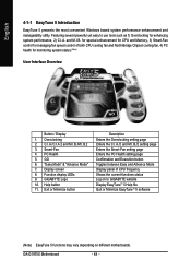
PC Health 5. Display screen 8. Help button 11. GO 6. GIGABYTE Logo 10. for special enhancement for CPU and Memory, 3) Smart-Fan control for managing fan speed control of both CPU cooling fan and North-Bridge Chipset cooling fan, 4) PC ...Log on to use tools such as 1) Overclocking for monitoring system status.(Note) User Interface Overview Button / Display 1. GA-G1975X Motherboard - 64 - Featuring several powerful yet easy to GIGABYTE website Display EasyTuneTM 5 Help file Quit or Minimize EasyTuneTM 5 software (Note) EasyTune 5 functions may vary depending on ...
PC Health 5. Display screen 8. Help button 11. GO 6. GIGABYTE Logo 10. for special enhancement for CPU and Memory, 3) Smart-Fan control for managing fan speed control of both CPU cooling fan and North-Bridge Chipset cooling fan, 4) PC ...Log on to use tools such as 1) Overclocking for monitoring system status.(Note) User Interface Overview Button / Display 1. GA-G1975X Motherboard - 64 - Featuring several powerful yet easy to GIGABYTE website Display EasyTuneTM 5 Help file Quit or Minimize EasyTuneTM 5 software (Note) EasyTune 5 functions may vary depending on ...
Manual
Page 65
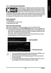
... to provide quick backup and restoration of the screen. VESA-supported VGA cards How to boot from the CD-ROM, you complete installations of system memory 3. Save the settings and exit the BIOS Setup. After the steps above are completed, subsequent access to Xpress Recovery2 can be immediately installed once you...
... to provide quick backup and restoration of the screen. VESA-supported VGA cards How to boot from the CD-ROM, you complete installations of system memory 3. Save the settings and exit the BIOS Setup. After the steps above are completed, subsequent access to Xpress Recovery2 can be immediately installed once you...


