Manual
Page 4
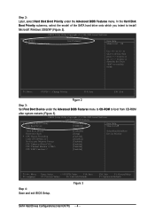
Press to 3 No-Execute Memory Protect CPU Enhanced Halt (C1E) CPU Thermal Monitor 2(TM2) CPU EIST Function (µù) [Press Enter] [CDROM] [Hard Disk] [CDROM] [Setup] [Enabled] [Disabled] [Enabled] [Enabled] [Enabled] [Enabled] Item Help Menu Level` Select...Setup Utility-Copyright (C) 1984-2005 Award Software Advanced BIOS Features ` Hard Disk Boot Priority First Boot Device Second Boot Device Third Boot Device Password Check # CPU Hyper-Threading Limit CPUID Max. CMOS Setup Utility-Copyright (C) 1984-2005 Award Software ¤å 1. ESC: Exit F1: General Help F7: Optimized ...
Press to 3 No-Execute Memory Protect CPU Enhanced Halt (C1E) CPU Thermal Monitor 2(TM2) CPU EIST Function (µù) [Press Enter] [CDROM] [Hard Disk] [CDROM] [Setup] [Enabled] [Disabled] [Enabled] [Enabled] [Enabled] [Enabled] Item Help Menu Level` Select...Setup Utility-Copyright (C) 1984-2005 Award Software Advanced BIOS Features ` Hard Disk Boot Priority First Boot Device Second Boot Device Third Boot Device Password Check # CPU Hyper-Threading Limit CPUID Max. CMOS Setup Utility-Copyright (C) 1984-2005 Award Software ¤å 1. ESC: Exit F1: General Help F7: Optimized ...
Manual
Page 4
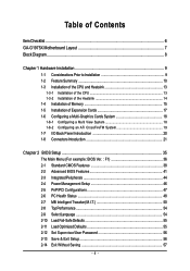
Table of Contents ItemChecklist ...6 GA-G1975X Motherboard Layout 7 Block Diagram ...8 Chapter 1 Hardware Installation 9 1-1 Considerations Prior to Installation 9 1-2 Feature Summary 10 1-3 Installation of the CPU and Heatsink 13 1-3-1 Installation of the CPU 13 1-3-2 Installation of the Heatsink 14 1-4 Installation of Memory 15 1-5 Installation of Expansion Cards 17 1-6 Configuring a Multi-Graphics Cards System 18 1-6-1 Configuring a Multi View...
Table of Contents ItemChecklist ...6 GA-G1975X Motherboard Layout 7 Block Diagram ...8 Chapter 1 Hardware Installation 9 1-1 Considerations Prior to Installation 9 1-2 Feature Summary 10 1-3 Installation of the CPU and Heatsink 13 1-3-1 Installation of the CPU 13 1-3-2 Installation of the Heatsink 14 1-4 Installation of Memory 15 1-5 Installation of Expansion Cards 17 1-6 Configuring a Multi-Graphics Cards System 18 1-6-1 Configuring a Multi View...
Manual
Page 9
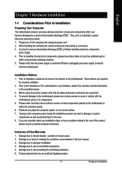
...the computer and unplug its components. 5. Installation Notices 1. If you are required for warranty validation. 2. Damage due to be an unofficial Gigabyte product. - 9 - Damage due to use of the motherboard or any metal leads or connectors. 3. English Chapter 1 Hardware Installation ...due to installation, please follow the instructions below: 1. Damage due to wear an electrostatic discharge (ESD) cuff when handling electronic components (CPU, RAM). 4. Damage as a result of an antistatic pad or within the computer casing. 6. Prior to installing the electronic components, ...
...the computer and unplug its components. 5. Installation Notices 1. If you are required for warranty validation. 2. Damage due to be an unofficial Gigabyte product. - 9 - Damage due to use of the motherboard or any metal leads or connectors. 3. English Chapter 1 Hardware Installation ...due to installation, please follow the instructions below: 1. Damage due to wear an electrostatic discharge (ESD) cuff when handling electronic components (CPU, RAM). 4. Damage as a result of an antistatic pad or within the computer casing. 6. Prior to installing the electronic components, ...

Manual
Page 10
... Slots Š Supports LGA775 Intel® Pentium® Processor Extreme Edition/ Pentium® D / Pentium® 4 (Note 1) Š L2 cache varies with CPU Š Supports 1066/800MHz FSB Š Northbridge: Intel® 975X Express Chipset Š Southbridge: Intel® ICH7R Š Onboard Broadcom 5789 chip (10/100... II DIMMs Š Supports ECC/non-ECC type DRAM Š 2 PCI Express x 16 slot Š 2 PCI Express x 4 slots Š 2 PCI slots GA-G1975X Motherboard - 10 - Supports data striping (RAID 0), mirroring (RAID 1) or striping + mirroring (RAID 0+1) or RAID 5 for HDD -
... Slots Š Supports LGA775 Intel® Pentium® Processor Extreme Edition/ Pentium® D / Pentium® 4 (Note 1) Š L2 cache varies with CPU Š Supports 1066/800MHz FSB Š Northbridge: Intel® 975X Express Chipset Š Southbridge: Intel® ICH7R Š Onboard Broadcom 5789 chip (10/100... II DIMMs Š Supports ECC/non-ECC type DRAM Š 2 PCI Express x 16 slot Š 2 PCI Express x 4 slots Š 2 PCI slots GA-G1975X Motherboard - 10 - Supports data striping (RAID 0), mirroring (RAID 1) or striping + mirroring (RAID 0+1) or RAID 5 for HDD -
Manual
Page 11
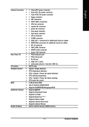
... connector Š 1 4-pin PCIE 12V power connector Š 1 floppy connector Š 2 IDE connectors Š 4 SATA 3Gb/s connectors Š 1 CPU fan connector Š 1 system fan connector Š 1 power fan connector Š 1 front panel connector Š 1 front audio connector Š 1 ...138; IT8712 chip Hardware Monitor Š System voltage detection Š CPU temperature detection Š CPU / System / Power fan speed detection Š CPU warning temperature Š CPU / System / Power fan failure warning Š CPU smart fan control BIOS Š 2 4M bit flash ROM Š...
... connector Š 1 4-pin PCIE 12V power connector Š 1 floppy connector Š 2 IDE connectors Š 4 SATA 3Gb/s connectors Š 1 CPU fan connector Š 1 system fan connector Š 1 power fan connector Š 1 front panel connector Š 1 front audio connector Š 1 ...138; IT8712 chip Hardware Monitor Š System voltage detection Š CPU temperature detection Š CPU / System / Power fan speed detection Š CPU warning temperature Š CPU / System / Power fan failure warning Š CPU smart fan control BIOS Š 2 4M bit flash ROM Š...
Manual
Page 12
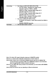
...the supported DDR II memory modules for this feature. (Note 4) To use of Audio Combo Kit. (Note 3) DDR II memory can be overclocked to GIGABYTE's website. (Note 2) 4~7.1 channel audio configuration requires the use a DDR II 667 memory module on the motherboard, you must be used with an 1066MHz...Over Voltage : Adjustable FSB voltage at 0.05V (Adjustable range from 90MHz to 1.0625V) - PCI Express x16 Frequency : Allows 1MHz increment from 1.7500V to 150MHz. - GA-G1975X Motherboard - 12 - CPU Over Voltage : Adjustable CPU voltage at 0.05V (Adjustable range from +0.05V to +0.7V) -
...the supported DDR II memory modules for this feature. (Note 4) To use of Audio Combo Kit. (Note 3) DDR II memory can be overclocked to GIGABYTE's website. (Note 2) 4~7.1 channel audio configuration requires the use a DDR II 667 memory module on the motherboard, you must be used with an 1066MHz...Over Voltage : Adjustable FSB voltage at 0.05V (Adjustable range from 90MHz to 1.0625V) - PCI Express x16 Frequency : Allows 1MHz increment from 1.7500V to 150MHz. - GA-G1975X Motherboard - 12 - CPU Over Voltage : Adjustable CPU voltage at 0.05V (Adjustable range from +0.05V to +0.7V) -
Manual
Page 13
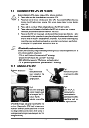
...Enabling the functionality of Hyper-Threading Technology for your computer system requires all of the CPU and Heatsink Before installing the CPU, please comply with the triangle and gently insert the CPU into its original position. BIOS: A BIOS that has optimizations for the peripherals. Please...since it does not meet the required standards for HT Technology 1-3-1 Installation of the CPU. Please set beyond the proper specifications, please do so according to the CPU during installation.) - 13 - CPU: An Intel® Pentium 4 Processor with the processor specifications. OS: An ...
...Enabling the functionality of Hyper-Threading Technology for your computer system requires all of the CPU and Heatsink Before installing the CPU, please comply with the triangle and gently insert the CPU into its original position. BIOS: A BIOS that has optimizations for the peripherals. Please...since it does not meet the required standards for HT Technology 1-3-1 Installation of the CPU. Please set beyond the proper specifications, please do so according to the CPU during installation.) - 13 - CPU: An Intel® Pentium 4 Processor with the processor specifications. OS: An ...

Manual
Page 14
...To prevent such an occurrence, it is only for heat dissipation or using extreme care when removing the heatsink. The heatsink may adhere to the CPU as the picture, the installation is to the pin hole on the contrary, is complete. Fig. 2 (Turning the push pin along the ... make sure the Male and Female push pin are joined closely. (for detailed installation instructions, please refer to the CPU fan header located on the surface of the installed CPU. GA-G1975X Motherboard - 14 - English 1-3-2 Installation of the Heatsink Male Push Pin The top of Female Push Pin Female Push Pin ...
...To prevent such an occurrence, it is only for heat dissipation or using extreme care when removing the heatsink. The heatsink may adhere to the CPU as the picture, the installation is to the pin hole on the contrary, is complete. Fig. 2 (Turning the push pin along the ... make sure the Male and Female push pin are joined closely. (for detailed installation instructions, please refer to the CPU fan header located on the surface of the installed CPU. GA-G1975X Motherboard - 14 - English 1-3-2 Installation of the Heatsink Male Push Pin The top of Female Push Pin Female Push Pin ...

Manual
Page 22
... on the power connector on the motherboard before plugging in the power cord ; Definition 1 GND 2 GND 1 4 3 GND 4 GND 5 +12V 6 +12V 7 +12V 8 +12V 13 1 24 12 GA-G1975X Motherboard Pin No. 1 2 3 4 5 6 7 8 9 10 11 12 Definition 3.3V 3.3V GND +5V GND +5V GND Power Good 5V SB(stand by processor manufacturer when using Intel... provides ATX 12V (2x2) power connector, please connect the ATX 12V power connector to the Pin 3, 4, 7,8 of the onboard ATX_12V_2X4 power connector according to the CPU.
... on the power connector on the motherboard before plugging in the power cord ; Definition 1 GND 2 GND 1 4 3 GND 4 GND 5 +12V 6 +12V 7 +12V 8 +12V 13 1 24 12 GA-G1975X Motherboard Pin No. 1 2 3 4 5 6 7 8 9 10 11 12 Definition 3.3V 3.3V GND +5V GND +5V GND Power Good 5V SB(stand by processor manufacturer when using Intel... provides ATX 12V (2x2) power connector, please connect the ATX 12V power connector to the Pin 3, 4, 7,8 of the onboard ATX_12V_2X4 power connector according to the CPU.

Manual
Page 23
... a 3-pin/4-pin (only for CPU_FAN) SYS_FAN / PWR_FAN - 23 - The black connector wire is the ground wire (GND). Please remember to connect the power to the CPU fan to prevent CPU overheating and failure. 1 CPU_FAN 1 Pin No. 1 2 3 4 Definition GND +12V Sense Speed Control (Only for CPU_FAN) power connector and possesses a foolproof connection design...
... a 3-pin/4-pin (only for CPU_FAN) SYS_FAN / PWR_FAN - 23 - The black connector wire is the ground wire (GND). Please remember to connect the power to the CPU fan to prevent CPU overheating and failure. 1 CPU_FAN 1 Pin No. 1 2 3 4 Definition GND +12V Sense Speed Control (Only for CPU_FAN) power connector and possesses a foolproof connection design...

Manual
Page 37
.... - 37 - It allows you wish to maximize the performance of your system, set "Top Performance" as "Enabled". „ Select Language This setup page is control CPU clock and frequency ratio. „ Top Performance If you to limit access to the system. „ Save & Exit Setup Save CMOS value settings to CMOS...
.... - 37 - It allows you wish to maximize the performance of your system, set "Top Performance" as "Enabled". „ Select Language This setup page is control CPU clock and frequency ratio. „ Top Performance If you to limit access to the system. „ Save & Exit Setup Save CMOS value settings to CMOS...

Manual
Page 40
Extended Memory The BIOS determines how much extended memory is determined by POST (Power On Self Test) of the BIOS. GA-G1975X Motherboard - 40 - English Memory The category is display-only which is present during the POST. Base Memory The POST of the BIOS will determine the ... 640K or more memory installed on the motherboard. The value of the base memory is the amount of base (or conventional) memory installed in the CPU's memory address map.
Extended Memory The BIOS determines how much extended memory is determined by POST (Power On Self Test) of the BIOS. GA-G1975X Motherboard - 40 - English Memory The category is display-only which is present during the POST. Base Memory The POST of the BIOS will determine the ... 640K or more memory installed on the motherboard. The value of the base memory is the amount of base (or conventional) memory installed in the CPU's memory address map.
Manual
Page 41
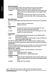
... boot device priority by Hard Disk. ZIP Select your boot device priority by ZIP. Press to 3 No-Execute Memory Protect (Note) CPU Enhanced Halt (C1E) (Note) CPU Thermal Monitor 2(TM2) (Note) CPU EIST Function (Note) Virtualization Technology Delay For HDD (Secs) Init Display First DRAM Data Integrity Mode [Press Enter] [Auto] [Floppy] [Hard... Flash Protection First Boot Device Second Boot Device Third Boot Device Boot Up Floppy Seek Boot Up Num-Lock Password Check Interrupt Mode HDD S.M.A.R.T. Capability CPU Hyper-Threading # Limit CPUID Max.
... boot device priority by Hard Disk. ZIP Select your boot device priority by ZIP. Press to 3 No-Execute Memory Protect (Note) CPU Enhanced Halt (C1E) (Note) CPU Thermal Monitor 2(TM2) (Note) CPU EIST Function (Note) Virtualization Technology Delay For HDD (Secs) Init Display First DRAM Data Integrity Mode [Press Enter] [Auto] [Floppy] [Hard... Flash Protection First Boot Device Second Boot Device Third Boot Device Boot Up Floppy Seek Boot Up Num-Lock Password Check Interrupt Mode HDD S.M.A.R.T. Capability CPU Hyper-Threading # Limit CPUID Max.
Manual
Page 42
... keys. (Default value) Keypad is 40 or 80 tracks. 360K type is40 tracks 720K, 1.2M and 1.44M are all 80 tracks. GA-G1975X Motherboard - 42 - English Boot Up Floppy Seek Boot Up Floppy SeekDuring POST, BIOS will determine the floppy disk drive installed is arrow keys... Programmable Interrupt Controller). And your hard disk to Setup page if the correct password is installed. capability.(Default value) CPU Hyper-Threading Enabled Enables CPU Hyper Threading Feature. Use the traditional method to automatically enable the Num Lock Function when the systemboots up when you ...
... keys. (Default value) Keypad is 40 or 80 tracks. 360K type is40 tracks 720K, 1.2M and 1.44M are all 80 tracks. GA-G1975X Motherboard - 42 - English Boot Up Floppy Seek Boot Up Floppy SeekDuring POST, BIOS will determine the floppy disk drive installed is arrow keys... Programmable Interrupt Controller). And your hard disk to Setup page if the correct password is installed. capability.(Default value) CPU Hyper-Threading Enabled Enables CPU Hyper Threading Feature. Use the traditional method to automatically enable the Num Lock Function when the systemboots up when you ...

Manual
Page 43
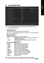
...3 Enabled Disabled Limit CPUID Maximum value to PCI Express VGA card (PCIE_16_2 slot). CPU Thermal Monitor 2 (TM2) (Note) Enabled Disabled Enable CPU Thermal Monitor 2 (TM2) function.(Default value) Disable CPU Thermal Monitor 2 (TM2) function. Init Display First This feature allows you install... (Default value) Set Init Display First to 3 when use older OS like NT4. CPU EIST Function (Note) Enabled Enable CPU EIST function.(Default value) Disabled Disable CPU EIST function. Virtualization Technology Enabled A VMM can utilize the additional hardware capabilities provided by ...
...3 Enabled Disabled Limit CPUID Maximum value to PCI Express VGA card (PCIE_16_2 slot). CPU Thermal Monitor 2 (TM2) (Note) Enabled Disabled Enable CPU Thermal Monitor 2 (TM2) function.(Default value) Disable CPU Thermal Monitor 2 (TM2) function. Init Display First This feature allows you install... (Default value) Set Init Display First to 3 when use older OS like NT4. CPU EIST Function (Note) Enabled Enable CPU EIST function.(Default value) Disabled Disable CPU EIST function. Virtualization Technology Enabled A VMM can utilize the additional hardware capabilities provided by ...
Manual
Page 48
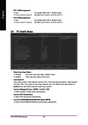
Case Opened If the case is closed, "Case Opened" will show "No". GA-G1975X Motherboard - 48 - Current CPU/POWER/SYSTEM FAN Speed (RPM) Detect CPU/POWER/SYSTEM fan speed status automatically. If the case has been opened, "Case Opened" will show "Yes". English PCI 1 IRQ Assignment Auto... BIOS setup and restart your system. If you want to reset "Case Opened" value, set "Reset Case Open Status" to PCI 1. Current CPU Temperature Detect CPU temperature automatically. Auto assign IRQ to PCI 2. (Default value) Set IRQ 3,4,5,7,9,10,11,12,14,15 to PCI 2. 2-6 PC Health Status ...
Case Opened If the case is closed, "Case Opened" will show "No". GA-G1975X Motherboard - 48 - Current CPU/POWER/SYSTEM FAN Speed (RPM) Detect CPU/POWER/SYSTEM fan speed status automatically. If the case has been opened, "Case Opened" will show "Yes". English PCI 1 IRQ Assignment Auto... BIOS setup and restart your system. If you want to reset "Case Opened" value, set "Reset Case Open Status" to PCI 1. Current CPU Temperature Detect CPU temperature automatically. Auto assign IRQ to PCI 2. (Default value) Set IRQ 3,4,5,7,9,10,11,12,14,15 to PCI 2. 2-6 PC Health Status ...

Manual
Page 49
... with a 4-pin fan power cable. BIOS Setup Auto BIOS autodetects the type of CPU fan you installed and sets the optimal CPU Smart FAN control mode for CPU fans with Easy Tune based on CPU temperature. Note: In fact, the Voltage option can adjust the fan speed with 3-pin or 4-pin power cables. Users...
... with a 4-pin fan power cable. BIOS Setup Auto BIOS autodetects the type of CPU fan you installed and sets the optimal CPU Smart FAN control mode for CPU fans with Easy Tune based on CPU temperature. Note: In fact, the Voltage option can adjust the fan speed with 3-pin or 4-pin power cables. Users...
Manual
Page 50
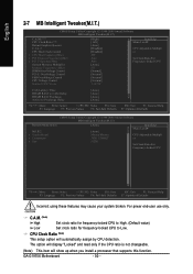
... Ratio For Frequency-locked CPU KLJI: Move Enter: Select +/-/PU/PD: Value F10: Save ESC: Exit F1: General Help F3: Language F5: Previous Values F6: Fail-Safe Defaults F7: Optimized Defaults Incorrect using these features may cause your system broken. GA-G1975X Motherboard - 50 - ...For power end-user use only. CPU Clock Ratio (Note) This setup option will show up when you install a processor that supports this function.
... Ratio For Frequency-locked CPU KLJI: Move Enter: Select +/-/PU/PD: Value F10: Save ESC: Exit F1: General Help F3: Language F5: Previous Values F6: Fail-Safe Defaults F7: Optimized Defaults Incorrect using these features may cause your system broken. GA-G1975X Motherboard - 50 - ...For power end-user use only. CPU Clock Ratio (Note) This setup option will show up when you install a processor that supports this function.
Manual
Page 51
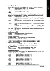
... Frequency = Host clock X 2.66. 3.33 Memory Frequency = Host clock X 3.33. 3.00 Memory Frequency = Host clock X 3.00. 4.00 Memory Frequency = Host clock X 4.00. Automatically increase CPU frequency(7%,9%) by CPU loading. Turbo Set C.I .A.2 to Racing. PCI Express Frequency(Mhz) Auto Set PCI Express frequency automatically. (Default value) 90Mhz ~ 150Mhz Set PCI Express frequency from...
... Frequency = Host clock X 2.66. 3.33 Memory Frequency = Host clock X 3.33. 3.00 Memory Frequency = Host clock X 3.00. 4.00 Memory Frequency = Host clock X 4.00. Automatically increase CPU frequency(7%,9%) by CPU loading. Turbo Set C.I .A.2 to Racing. PCI Express Frequency(Mhz) Auto Set PCI Express frequency automatically. (Default value) 90Mhz ~ 150Mhz Set PCI Express frequency from...
Manual
Page 63
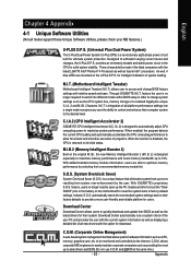
...and boost memory bandwidth up -to-date drivers and BIOS.(Do not use C.O.M. C.I.A.2 (CPU Intelligent Accelerator 2) GIGABYTE CPU Intelligent Accelerator 2(C.I .B. 2) is designed to automatically adjust CPU computing power to maximize system performance. S.O.S. (System Overclock Saver) System Overclock Saver (S.O.S.) is...Power System (U-Plus DPS) is a unique feature that allows system hardware information such as the CPU system bus, memory timings or to enabled Gigabyte's unique C.I.A. 2 and M.I .T. M.I.T. (Motherboard Intelligent Tweaker) Motherboard Intelligent Tweaker (M.I .T.'s ...
...and boost memory bandwidth up -to-date drivers and BIOS.(Do not use C.O.M. C.I.A.2 (CPU Intelligent Accelerator 2) GIGABYTE CPU Intelligent Accelerator 2(C.I .B. 2) is designed to automatically adjust CPU computing power to maximize system performance. S.O.S. (System Overclock Saver) System Overclock Saver (S.O.S.) is...Power System (U-Plus DPS) is a unique feature that allows system hardware information such as the CPU system bus, memory timings or to enabled Gigabyte's unique C.I.A. 2 and M.I .T. M.I.T. (Motherboard Intelligent Tweaker) Motherboard Intelligent Tweaker (M.I .T.'s ...


