
Manual
Page 1
Table of Contents Configuring SATA Hard Drive(s) (Controller: Intel ICH7R 2 (1) Installing SATA hard drive(s) in your computer 2 (2) Configuring SATA controller mode and boot sequence in BIOS Setup 3 (3) Configuring RAID set in RAID BIOS 5 (4) Making a SATA Driver Disk ...9 (5) Installing SATA controller driver during OS installation 11
Table of Contents Configuring SATA Hard Drive(s) (Controller: Intel ICH7R 2 (1) Installing SATA hard drive(s) in your computer 2 (2) Configuring SATA controller mode and boot sequence in BIOS Setup 3 (3) Configuring RAID set in RAID BIOS 5 (4) Making a SATA Driver Disk ...9 (5) Installing SATA controller driver during OS installation 11
Manual
Page 2
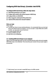
... configure SATA hard drive(s), follow the steps below: ¤å (1) Install SATA hard drive(s) in your system. (2) Configure SATA controller mode and boot sequence in BIOS Setup. (3)* Configure RAID set in your computer Attach one hard drive. (b) An empty formatted floppy disk. (c) Windows XP/2000 setup disk. (d) Driver CD for your...
... configure SATA hard drive(s), follow the steps below: ¤å (1) Install SATA hard drive(s) in your system. (2) Configure SATA controller mode and boot sequence in BIOS Setup. (3)* Configure RAID set in your computer Attach one hard drive. (b) An empty formatted floppy disk. (c) Windows XP/2000 setup disk. (d) Driver CD for your...
Manual
Page 3
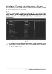
...to create RAID, set SATA RAID/AHCI Mode under the Integrated Peripherals menu to make sure whether the SATA controller is configured correctly in system BIOS Setup and set On-Chip SATA Mode to Manual or Auto (default) based on your computer and press Del to USB Controller USB 2.0 ... Enter: Select +/-/PU/PD: Value F10: Save F5: Previous Values F6: Fail-Safe Defaults ESC: Exit F1: General Help F7: Optimized Defaults Figure 1 The BIOS Setup menus described in this section may not show the exact settings for the SATA hard drive(s). If you have to RAID (Disabled by default).
...to create RAID, set SATA RAID/AHCI Mode under the Integrated Peripherals menu to make sure whether the SATA controller is configured correctly in system BIOS Setup and set On-Chip SATA Mode to Manual or Auto (default) based on your computer and press Del to USB Controller USB 2.0 ... Enter: Select +/-/PU/PD: Value F10: Save F5: Previous Values F6: Fail-Safe Defaults ESC: Exit F1: General Help F7: Optimized Defaults Figure 1 The BIOS Setup menus described in this section may not show the exact settings for the SATA hard drive(s). If you have to RAID (Disabled by default).
Manual
Page 4
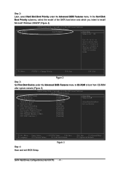
..., or to exit this menu. KL: Move PU/PD/+/-: Change Priority F10: Save ESC: Exit Figure 2 Step 3: Set First Boot Device under the Advanced BIOS Features menu. ESC: Exit F1: General Help F7: Optimized Defaults SATA Hard Drives Configurations (Intel ICH7R) - 4 - CMOS Setup Utility-Copyright (C) 1984-2005... Intel Volume0 Item Help 2. Press to move it down the list. Ác Step 2: Later, select Hard Disk Boot Priority under the Advanced BIOS Features menu to CD-ROM to boot from CD-ROM after system restarts (Figure 3). In the Hard Disk Åé Boot Priority submenu, ...
..., or to exit this menu. KL: Move PU/PD/+/-: Change Priority F10: Save ESC: Exit Figure 2 Step 3: Set First Boot Device under the Advanced BIOS Features menu. ESC: Exit F1: General Help F7: Optimized Defaults SATA Hard Drives Configurations (Intel ICH7R) - 4 - CMOS Setup Utility-Copyright (C) 1984-2005... Intel Volume0 Item Help 2. Press to move it down the list. Ác Step 2: Later, select Hard Disk Boot Priority under the Advanced BIOS Features menu to CD-ROM to boot from CD-ROM after system restarts (Figure 3). In the Hard Disk Åé Boot Priority submenu, ...
Manual
Page 5
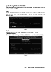
... Volume 3. Skip this step and proceed to Section 4 if you want to create RAID array, select Create RAID Volume in RAID BIOS Enter the RAID BIOS setup utility to enter the RAID BIOS setup utility. Step 1: After the POST memory test begins and before the operating system boot begins, look for a message which...
... Volume 3. Skip this step and proceed to Section 4 if you want to create RAID array, select Create RAID Volume in RAID BIOS Enter the RAID BIOS setup utility to enter the RAID BIOS setup utility. Step 1: After the POST memory test begins and before the operating system boot begins, look for a message which...
Manual
Page 8
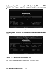
... Size Type/Status(Vol ID) 111.8GB Member Disk(0) 111.8GB Member Disk(0) [KL]-Select [ESC]-Exit [ENTER]-Select Menu To exit the ICH7R RAID BIOS utility, press ESC in Main Menu. Now, you can see detailed information about the RAID Array in the DISK/ VOLUME INFORMATION section, including RAID mode...
... Size Type/Status(Vol ID) 111.8GB Member Disk(0) 111.8GB Member Disk(0) [KL]-Select [ESC]-Exit [ENTER]-Select Menu To exit the ICH7R RAID BIOS utility, press ESC in Main Menu. Now, you can see detailed information about the RAID Array in the DISK/ VOLUME INFORMATION section, including RAID mode...
Manual
Page 11
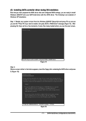
Figure 15 Step 2: When a screen similar to that you have prepared the SATA driver disk and configured BIOS settings, you do not have any device support disks from the Windows 2000/XP Setup disk and press F6 as soon as you see the "...
Figure 15 Step 2: When a screen similar to that you have prepared the SATA driver disk and configured BIOS settings, you do not have any device support disks from the Windows 2000/XP Setup disk and press F6 as soon as you see the "...
Manual
Page 4
Table of Contents ItemChecklist ...6 GA-G1975X Motherboard Layout 7 Block Diagram ...8 Chapter 1 Hardware Installation 9 1-1 Considerations Prior to Installation 9 1-2 Feature Summary 10 1-3 Installation of the CPU and Heatsink ...18 1-6-2 Configuring an ATi CrossFireTM System 19 1-7 I/O Back Panel Introduction 20 1-8 Connectors Introduction 21 Chapter 2 BIOS Setup 35 The Main Menu (For example: BIOS Ver. : F1 36 2-1 Standard CMOS Features 38 2-2 Advanced BIOS Features 41 2-3 IntegratedPeripherals 44 2-4 Power Management Setup 46 2-5 PnP/PCI Configurations 47 2-6 PC Health Status ...
Table of Contents ItemChecklist ...6 GA-G1975X Motherboard Layout 7 Block Diagram ...8 Chapter 1 Hardware Installation 9 1-1 Considerations Prior to Installation 9 1-2 Feature Summary 10 1-3 Installation of the CPU and Heatsink ...18 1-6-2 Configuring an ATi CrossFireTM System 19 1-7 I/O Back Panel Introduction 20 1-8 Connectors Introduction 21 Chapter 2 BIOS Setup 35 The Main Menu (For example: BIOS Ver. : F1 36 2-1 Standard CMOS Features 38 2-2 Advanced BIOS Features 41 2-3 IntegratedPeripherals 44 2-4 Power Management Setup 46 2-5 PnP/PCI Configurations 47 2-6 PC Health Status ...
Manual
Page 5
Channel Audio Function Introduction 90 4-1-6 DTS Introduction 96 4-2 Troubleshooting 103 4-3 POST Error Code 104 - 5 - Chapter 3 Drivers Installation 59 3-1 Install Chipset Drivers 59 3-2 SoftwareApplications 60 3-3 Driver CD Information 60 3-4 Hardware Information 61 3-5 Contact Us ...61 Chapter 4 Appendix 63 4-1 Unique Software Utilities 63 4-1-1 EasyTune 5 Introduction 64 4-1-2 Xpress Recovery2 Introduction 65 4-1-3 Flash BIOS Method Introduction 67 4-1-4 Configuring SATA Hard Drive(s) (Controller: Intel ICH7R 79 4-1-5 2- / 4- / 5.1- / 6.1- / 7.1-
Channel Audio Function Introduction 90 4-1-6 DTS Introduction 96 4-2 Troubleshooting 103 4-3 POST Error Code 104 - 5 - Chapter 3 Drivers Installation 59 3-1 Install Chipset Drivers 59 3-2 SoftwareApplications 60 3-3 Driver CD Information 60 3-4 Hardware Information 61 3-5 Contact Us ...61 Chapter 4 Appendix 63 4-1 Unique Software Utilities 63 4-1-1 EasyTune 5 Introduction 64 4-1-2 Xpress Recovery2 Introduction 65 4-1-3 Flash BIOS Method Introduction 67 4-1-4 Configuring SATA Hard Drive(s) (Controller: Intel ICH7R 79 4-1-5 2- / 4- / 5.1- / 6.1- / 7.1-
Manual
Page 7
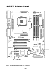
GA-G1975X PWR_FAN IT8712F GA-G1975X Motherboard Layout KB_MS AUDIO LGA775 CPU_FAN ATX_12V_2X4 ATX PWR_FAN USB F_AUDIO LAN Intel® 975X CD_IN Broadcom 5789 PCIE_16_1 PCIE1 SUR_CEN PCIE2 PCIE_16_2 PCIE_4_1 SPDIF_IO PCIE_4_2 COMA PW1 PCIE_12V FDD IDE1 DDRII1 DDRII2 DDRII3 DDRII4 CI Intel® ICH7R MAIN BIOS SYS_FAN BACKUP BIOS CREATIVE CA0106 BAT TSB43AB23 F_USB1 F_USB2 F1_1394 F2_1394 PW2 IDE2 S_ATAII0_1 GREEN_USB IT8211F PWR_LED F_PANEL S_ATAII2_3 RF_ID Debug LED (Note) (Note) For error code information, please refer to page 104. - 7 -
GA-G1975X PWR_FAN IT8712F GA-G1975X Motherboard Layout KB_MS AUDIO LGA775 CPU_FAN ATX_12V_2X4 ATX PWR_FAN USB F_AUDIO LAN Intel® 975X CD_IN Broadcom 5789 PCIE_16_1 PCIE1 SUR_CEN PCIE2 PCIE_16_2 PCIE_4_1 SPDIF_IO PCIE_4_2 COMA PW1 PCIE_12V FDD IDE1 DDRII1 DDRII2 DDRII3 DDRII4 CI Intel® ICH7R MAIN BIOS SYS_FAN BACKUP BIOS CREATIVE CA0106 BAT TSB43AB23 F_USB1 F_USB2 F1_1394 F2_1394 PW2 IDE2 S_ATAII0_1 GREEN_USB IT8211F PWR_LED F_PANEL S_ATAII2_3 RF_ID Debug LED (Note) (Note) For error code information, please refer to page 104. - 7 -
Manual
Page 8
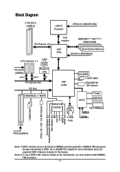
Go to GIGABYTE's website for more information about the supported DDR II memory modules for this feature. (Note 2) To use a DDR II 667 memory module on the ...-ECLK (100MHz) x4/x1 Broadcom 5789 x4/x1 x1 PCI Express Bus PCI Bus TSB43AB23 IT8211F Intel® ICH7R CREATIVE CA0106 2 PCI 8 USB Ports Dual BIOS 4 SATA 3Gb/s ATA33/66/100 IDE Channel IT8712 Floppy COM Port PS/2 KB/Mouse 24MHz 33MHz PCICLK(33MHz) 3 IEEE1394a ATA33 / 66 / 100 / 133 ...Out MIC Line-Out Line-In SPDIF In SPDIF Out (Note 1) DDR II memory can be used with a 1066MHz FSB processor) through overclocking in BIOS.
Go to GIGABYTE's website for more information about the supported DDR II memory modules for this feature. (Note 2) To use a DDR II 667 memory module on the ...-ECLK (100MHz) x4/x1 Broadcom 5789 x4/x1 x1 PCI Express Bus PCI Bus TSB43AB23 IT8211F Intel® ICH7R CREATIVE CA0106 2 PCI 8 USB Ports Dual BIOS 4 SATA 3Gb/s ATA33/66/100 IDE Channel IT8712 Floppy COM Port PS/2 KB/Mouse 24MHz 33MHz PCICLK(33MHz) 3 IEEE1394a ATA33 / 66 / 100 / 133 ...Out MIC Line-Out Line-In SPDIF In SPDIF Out (Note 1) DDR II memory can be used with a 1066MHz FSB processor) through overclocking in BIOS.
Manual
Page 11
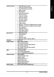
... Š CPU warning temperature Š CPU / System / Power fan failure warning Š CPU smart fan control BIOS Š 2 4M bit flash ROM Š Use of licensed AWARD BIOS Š Supports DualBIOS/Multilanguage BIOS Additional Features Š Supports @BIOS Š Supports Download Center Š Supports Q-Flash Š Supports EasyTune (Note 5) Š Supports Xpress Install Š...
... Š CPU warning temperature Š CPU / System / Power fan failure warning Š CPU smart fan control BIOS Š 2 4M bit flash ROM Š Use of licensed AWARD BIOS Š Supports DualBIOS/Multilanguage BIOS Additional Features Š Supports @BIOS Š Supports Download Center Š Supports Q-Flash Š Supports EasyTune (Note 5) Š Supports Xpress Install Š...
Manual
Page 12
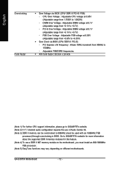
... 2) 4~7.1 channel audio configuration requires the use a DDR II 667 memory module on the motherboard, you must be overclocked to 1.0625V) - GA-G1975X Motherboard - 12 - Go to GIGABYTE's website for more information about the supported DDR II memory modules for this feature. (Note 4) To use of Audio Combo Kit. (Note .... PCI Express x16 Frequency : Allows 1MHz increment from +0.1V to 150MHz. - English Overclocking Form Factor Š Over Voltage via BIOS (CPU/ DDR II/ PCI-E) - CPU Over Voltage : Adjustable CPU voltage at 0.1V (Adjustable range from 90MHz to +0.7V) -
... 2) 4~7.1 channel audio configuration requires the use a DDR II 667 memory module on the motherboard, you must be overclocked to 1.0625V) - GA-G1975X Motherboard - 12 - Go to GIGABYTE's website for more information about the supported DDR II memory modules for this feature. (Note 4) To use of Audio Combo Kit. (Note .... PCI Express x16 Frequency : Allows 1MHz increment from +0.1V to 150MHz. - English Overclocking Form Factor Š Over Voltage via BIOS (CPU/ DDR II/ PCI-E) - CPU Over Voltage : Adjustable CPU voltage at 0.1V (Adjustable range from 90MHz to +0.7V) -
Manual
Page 13
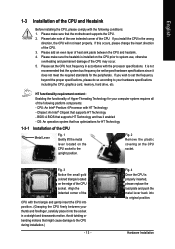
... CPU into position. (Grasping the CPU firmly between the CPU and heatsink. 4. If you wish to set the frequency beyond hardware specifications since it enabled - BIOS: A BIOS that might cause damage to the upright position. Align the indented corner of the CPU and Heatsink Before installing the CPU, please comply with the...
... CPU into position. (Grasping the CPU firmly between the CPU and heatsink. 4. If you wish to set the frequency beyond hardware specifications since it enabled - BIOS: A BIOS that might cause damage to the upright position. Align the indented corner of the CPU and Heatsink Before installing the CPU, please comply with the...
Manual
Page 15
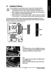
The motherboard supports DDR II memory modules, whereby BIOS will automatically detect memory capacity and specifications. Notch DDR II Fig.1 The DIMM socket has a notch, so the DIMM memory module can be inserted only ...
The motherboard supports DDR II memory modules, whereby BIOS will automatically detect memory capacity and specifications. Notch DDR II Fig.1 The DIMM socket has a notch, so the DIMM memory module can be inserted only ...
Manual
Page 17
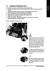
... slot. Please align the VGA card to the onboard PCI Express x 16 slot and press firmly down on the computer, if necessary, setup BIOS utility of expansion card from BIOS. 8. Installing a PCI Express x 16 expansion card: Please carefully pull out the small whitedrawable bar at the end of the PCI Express x 16...
... slot. Please align the VGA card to the onboard PCI Express x 16 slot and press firmly down on the computer, if necessary, setup BIOS utility of expansion card from BIOS. 8. Installing a PCI Express x 16 expansion card: Please carefully pull out the small whitedrawable bar at the end of the PCI Express x 16...

Manual
Page 25
... up to 300MB/s transfer rate. Plug the power cord and turn ON the computer. - 25 - Hardware Installation Re-install the battery. 4. Please refer to the BIOS setting for the Serial ATA and install the proper driver in the battery holder to make them short for about 10 minutes (Or you want...
... up to 300MB/s transfer rate. Plug the power cord and turn ON the computer. - 25 - Hardware Installation Re-install the battery. 4. Please refer to the BIOS setting for the Serial ATA and install the proper driver in the battery holder to make them short for about 10 minutes (Or you want...

Manual
Page 30
Definition 1 Signal 2 GND 1 GA-G1975X Motherboard - 30 - Definition 1 MPD+ 2 MPD- 1 3 MPD- 19) CI (Chassis Intrusion, Case Open) This 2-pin connector allows your system to indicate whether the system is removed. You can check the "Case Opened" status in BIOS Setup. Pin No. It will blink when the system enters suspend mode. English 18) PWR_LED The PWR_LED connector is connected with the system power indicator to detect if the chassis cover is on/off. Pin No.
Definition 1 Signal 2 GND 1 GA-G1975X Motherboard - 30 - Definition 1 MPD+ 2 MPD- 1 3 MPD- 19) CI (Chassis Intrusion, Case Open) This 2-pin connector allows your system to indicate whether the system is removed. You can check the "Case Opened" status in BIOS Setup. Pin No. It will blink when the system enters suspend mode. English 18) PWR_LED The PWR_LED connector is connected with the system power indicator to detect if the chassis cover is on/off. Pin No.
Manual
Page 35
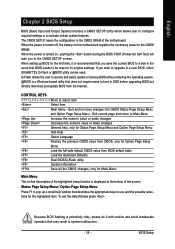
... -line description of the highlighted setup function is turned on, pushing the button during the BIOS POST (Power-On Self Test) will take you wish to upgrade to a new BIOS, either GIGABYTE's Q-Flash or @BIOS utility can be reset to its original settings. Status Page Setup Menu / Option Page Setup... Menu Press F1 to pop up BIOS for the highlighted item. CONTROL KEYS Move to quickly and easily update...
... -line description of the highlighted setup function is turned on, pushing the button during the BIOS POST (Power-On Self Test) will take you wish to upgrade to a new BIOS, either GIGABYTE's Q-Flash or @BIOS utility can be reset to its original settings. Status Page Setup Menu / Option Page Setup... Menu Press F1 to pop up BIOS for the highlighted item. CONTROL KEYS Move to quickly and easily update...

Manual
Page 36
...USB-CDROM USB-HDD LAN KL:Move Enter :Accept ESC:Exit The Main Menu (For example: BIOS Ver. : F1) Once you enter Award BIOS CMOS Setup Utility, the Main Menu (as usual. GA-G1975X Motherboard - 36 - Use arrow keys to select among the items and press to exit this chapter... are for reference only and may differ from the exact settings for G1975X F1 . . . . :BIOS Setup/Q-Flash, : Xpress Recovery2,...
...USB-CDROM USB-HDD LAN KL:Move Enter :Accept ESC:Exit The Main Menu (For example: BIOS Ver. : F1) Once you enter Award BIOS CMOS Setup Utility, the Main Menu (as usual. GA-G1975X Motherboard - 36 - Use arrow keys to select among the items and press to exit this chapter... are for reference only and may differ from the exact settings for G1975X F1 . . . . :BIOS Setup/Q-Flash, : Xpress Recovery2,...


