
Manual
Page 1
Table of Contents Configuring SATA Hard Drive(s) (Controller: Intel ICH7R 2 (1) Installing SATA hard drive(s) in your computer 2 (2) Configuring SATA controller mode and boot sequence in BIOS Setup 3 (3) Configuring RAID set in RAID BIOS 5 (4) Making a SATA Driver Disk ...9 (5) Installing SATA controller driver during OS installation 11
Table of Contents Configuring SATA Hard Drive(s) (Controller: Intel ICH7R 2 (1) Installing SATA hard drive(s) in your computer 2 (2) Configuring SATA controller mode and boot sequence in BIOS Setup 3 (3) Configuring RAID set in RAID BIOS 5 (4) Making a SATA Driver Disk ...9 (5) Installing SATA controller driver during OS installation 11
Manual
Page 2
Then connect the power connector from your system. (2) Configure SATA controller mode and boot sequence in BIOS Setup. (3)* Configure RAID set in RAID BIOS. (4) Make a floppy disk containing the SATA controller driver. (5) Install the SATA controller driver during OS installation. Ác Configuring SATA Hard Drive(s) (Controller: Intel ICH7R) Å&#...
Then connect the power connector from your system. (2) Configure SATA controller mode and boot sequence in BIOS Setup. (3)* Configure RAID set in RAID BIOS. (4) Make a floppy disk containing the SATA controller driver. (5) Install the SATA controller driver during OS installation. Ác Configuring SATA Hard Drive(s) (Controller: Intel ICH7R) Å&#...
Manual
Page 3
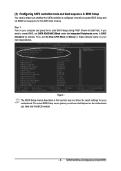
... F6: Fail-Safe Defaults ESC: Exit F1: General Help F7: Optimized Defaults Figure 1 The BIOS Setup menus described in system BIOS Setup and set BIOS boot sequence for your motherboard. The actual BIOS Setup menu options you will see shall depend on your computer and press Del to Manual or Auto... SATA Hard Drives Configurations (Intel ICH7R) Step 1: Turn on the motherboard you want to create RAID, set On-Chip SATA Mode to enter BIOS Setup during POST (Power-On Self Test). Then, set SATA RAID/AHCI Mode under the Integrated Peripherals menu to make sure whether the SATA ...
... F6: Fail-Safe Defaults ESC: Exit F1: General Help F7: Optimized Defaults Figure 1 The BIOS Setup menus described in system BIOS Setup and set BIOS boot sequence for your motherboard. The actual BIOS Setup menu options you will see shall depend on your computer and press Del to Manual or Auto... SATA Hard Drives Configurations (Intel ICH7R) Step 1: Turn on the motherboard you want to create RAID, set On-Chip SATA Mode to enter BIOS Setup during POST (Power-On Self Test). Then, set SATA RAID/AHCI Mode under the Integrated Peripherals menu to make sure whether the SATA ...
Manual
Page 4
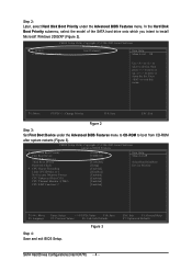
...: Save ESC: Exit Figure 2 Step 3: Set First Boot Device under the Advanced BIOS Features menu. Press to move it down the list. CMOS Setup Utility-Copyright (C) 1984-2005 Award Software Advanced BIOS Features ` Hard Disk Boot Priority First Boot Device Second Boot Device Third Boot Device ...PD: Value F10: Save F5: Previous Values F6: Fail-Safe Defaults Figure 3 Step 4: Save and exit BIOS Setup. Ác Step 2: Later, select Hard Disk Boot Priority under the Advanced BIOS Features menu to CD-ROM to boot from CD-ROM after system restarts (Figure 3). CMOS Setup Utility-Copyright ...
...: Save ESC: Exit Figure 2 Step 3: Set First Boot Device under the Advanced BIOS Features menu. Press to move it down the list. CMOS Setup Utility-Copyright (C) 1984-2005 Award Software Advanced BIOS Features ` Hard Disk Boot Priority First Boot Device Second Boot Device Third Boot Device ...PD: Value F10: Save F5: Previous Values F6: Fail-Safe Defaults Figure 3 Step 4: Save and exit BIOS Setup. Ác Step 2: Later, select Hard Disk Boot Priority under the Advanced BIOS Features menu to CD-ROM to boot from CD-ROM after system restarts (Figure 3). CMOS Setup Utility-Copyright ...
Manual
Page 5
...step and proceed to Section 4 if you do not want to enter Configuration Utility Figure 4 Step 2: After you want to enter the RAID BIOS setup utility. Intel(R) Matrix Storage Manager option ROM V5.0.0.1032 ICH7R wRAID5 Copyright(C) 2003-05 Intel Corporation. Reset Disks to configure a RAID array.... All Rights Reversed. Create RAID Volume¡G If you press CTRL+ I to create RAID array, select Create RAID Volume in RAID BIOS Enter the RAID BIOS setup utility to Non-RAID 4. SATA Hard Drives Configurations (Intel ICH7R) Step 1: After the POST memory test begins and before the ...
...step and proceed to Section 4 if you do not want to enter Configuration Utility Figure 4 Step 2: After you want to enter the RAID BIOS setup utility. Intel(R) Matrix Storage Manager option ROM V5.0.0.1032 ICH7R wRAID5 Copyright(C) 2003-05 Intel Corporation. Reset Disks to configure a RAID array.... All Rights Reversed. Create RAID Volume¡G If you press CTRL+ I to create RAID array, select Create RAID Volume in RAID BIOS Enter the RAID BIOS setup utility to Non-RAID 4. SATA Hard Drives Configurations (Intel ICH7R) Step 1: After the POST memory test begins and before the ...
Manual
Page 8
... Size Type/Status(Vol ID) 111.8GB Member Disk(0) 111.8GB Member Disk(0) [KL]-Select [ESC]-Exit [ENTER]-Select Menu To exit the ICH7R RAID BIOS utility, press ESC in Main Menu.
... Size Type/Status(Vol ID) 111.8GB Member Disk(0) 111.8GB Member Disk(0) [KL]-Select [ESC]-Exit [ENTER]-Select Menu To exit the ICH7R RAID BIOS utility, press ESC in Main Menu.
Manual
Page 11
... XP installation. SATA Hard Drives Configurations (Intel ICH7R) Figure 15 Step 2: When a screen similar to that you have prepared the SATA driver disk and configured BIOS settings, you are ready to install Windows 2000/XP onto your system, or you have any device support disks from the Windows 2000/XP Setup...
... XP installation. SATA Hard Drives Configurations (Intel ICH7R) Figure 15 Step 2: When a screen similar to that you have prepared the SATA driver disk and configured BIOS settings, you are ready to install Windows 2000/XP onto your system, or you have any device support disks from the Windows 2000/XP Setup...
Manual
Page 4
Table of Contents ItemChecklist ...6 GA-G1975X Motherboard Layout 7 Block Diagram ...8 Chapter 1 Hardware Installation 9 1-1 Considerations Prior to Installation 9 1-2 Feature Summary 10 1-3 Installation of the CPU and Heatsink ...18 1-6-2 Configuring an ATi CrossFireTM System 19 1-7 I/O Back Panel Introduction 20 1-8 Connectors Introduction 21 Chapter 2 BIOS Setup 35 The Main Menu (For example: BIOS Ver. : F1 36 2-1 Standard CMOS Features 38 2-2 Advanced BIOS Features 41 2-3 IntegratedPeripherals 44 2-4 Power Management Setup 46 2-5 PnP/PCI Configurations 47 2-6 PC Health Status ...
Table of Contents ItemChecklist ...6 GA-G1975X Motherboard Layout 7 Block Diagram ...8 Chapter 1 Hardware Installation 9 1-1 Considerations Prior to Installation 9 1-2 Feature Summary 10 1-3 Installation of the CPU and Heatsink ...18 1-6-2 Configuring an ATi CrossFireTM System 19 1-7 I/O Back Panel Introduction 20 1-8 Connectors Introduction 21 Chapter 2 BIOS Setup 35 The Main Menu (For example: BIOS Ver. : F1 36 2-1 Standard CMOS Features 38 2-2 Advanced BIOS Features 41 2-3 IntegratedPeripherals 44 2-4 Power Management Setup 46 2-5 PnP/PCI Configurations 47 2-6 PC Health Status ...
Manual
Page 5
Channel Audio Function Introduction 90 4-1-6 DTS Introduction 96 4-2 Troubleshooting 103 4-3 POST Error Code 104 - 5 - Chapter 3 Drivers Installation 59 3-1 Install Chipset Drivers 59 3-2 SoftwareApplications 60 3-3 Driver CD Information 60 3-4 Hardware Information 61 3-5 Contact Us ...61 Chapter 4 Appendix 63 4-1 Unique Software Utilities 63 4-1-1 EasyTune 5 Introduction 64 4-1-2 Xpress Recovery2 Introduction 65 4-1-3 Flash BIOS Method Introduction 67 4-1-4 Configuring SATA Hard Drive(s) (Controller: Intel ICH7R 79 4-1-5 2- / 4- / 5.1- / 6.1- / 7.1-
Channel Audio Function Introduction 90 4-1-6 DTS Introduction 96 4-2 Troubleshooting 103 4-3 POST Error Code 104 - 5 - Chapter 3 Drivers Installation 59 3-1 Install Chipset Drivers 59 3-2 SoftwareApplications 60 3-3 Driver CD Information 60 3-4 Hardware Information 61 3-5 Contact Us ...61 Chapter 4 Appendix 63 4-1 Unique Software Utilities 63 4-1-1 EasyTune 5 Introduction 64 4-1-2 Xpress Recovery2 Introduction 65 4-1-3 Flash BIOS Method Introduction 67 4-1-4 Configuring SATA Hard Drive(s) (Controller: Intel ICH7R 79 4-1-5 2- / 4- / 5.1- / 6.1- / 7.1-
Manual
Page 7
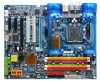
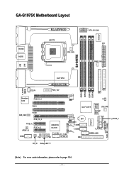
GA-G1975X PWR_FAN IT8712F GA-G1975X Motherboard Layout KB_MS AUDIO LGA775 CPU_FAN ATX_12V_2X4 ATX PWR_FAN USB F_AUDIO LAN Intel® 975X CD_IN Broadcom 5789 PCIE_16_1 PCIE1 SUR_CEN PCIE2 PCIE_16_2 PCIE_4_1 SPDIF_IO PCIE_4_2 COMA PW1 PCIE_12V FDD IDE1 DDRII1 DDRII2 DDRII3 DDRII4 CI Intel® ICH7R MAIN BIOS SYS_FAN BACKUP BIOS CREATIVE CA0106 BAT TSB43AB23 F_USB1 F_USB2 F1_1394 F2_1394 PW2 IDE2 S_ATAII0_1 GREEN_USB IT8211F PWR_LED F_PANEL S_ATAII2_3 RF_ID Debug LED (Note) (Note) For error code information, please refer to page 104. - 7 -
GA-G1975X PWR_FAN IT8712F GA-G1975X Motherboard Layout KB_MS AUDIO LGA775 CPU_FAN ATX_12V_2X4 ATX PWR_FAN USB F_AUDIO LAN Intel® 975X CD_IN Broadcom 5789 PCIE_16_1 PCIE1 SUR_CEN PCIE2 PCIE_16_2 PCIE_4_1 SPDIF_IO PCIE_4_2 COMA PW1 PCIE_12V FDD IDE1 DDRII1 DDRII2 DDRII3 DDRII4 CI Intel® ICH7R MAIN BIOS SYS_FAN BACKUP BIOS CREATIVE CA0106 BAT TSB43AB23 F_USB1 F_USB2 F1_1394 F2_1394 PW2 IDE2 S_ATAII0_1 GREEN_USB IT8211F PWR_LED F_PANEL S_ATAII2_3 RF_ID Debug LED (Note) (Note) For error code information, please refer to page 104. - 7 -
Manual
Page 8
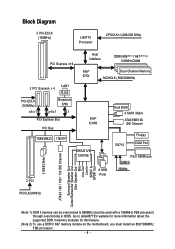
...-ECLK (100MHz) x4/x1 Broadcom 5789 x4/x1 x1 PCI Express Bus PCI Bus TSB43AB23 IT8211F Intel® ICH7R CREATIVE CA0106 2 PCI 8 USB Ports Dual BIOS 4 SATA 3Gb/s ATA33/66/100 IDE Channel IT8712 Floppy COM Port PS/2 KB/Mouse 24MHz 33MHz PCICLK(33MHz) 3 IEEE1394a ATA33 / 66 / 100 / 133 IDE ... Out Center/Subwoofer Speaker Out Side Speaker Out MIC Line-Out Line-In SPDIF In SPDIF Out (Note 1) DDR II memory can be overclocked to GIGABYTE's website for more information about the supported DDR II memory modules for this feature. (Note 2) To use a DDR II 667 memory module on the ...
...-ECLK (100MHz) x4/x1 Broadcom 5789 x4/x1 x1 PCI Express Bus PCI Bus TSB43AB23 IT8211F Intel® ICH7R CREATIVE CA0106 2 PCI 8 USB Ports Dual BIOS 4 SATA 3Gb/s ATA33/66/100 IDE Channel IT8712 Floppy COM Port PS/2 KB/Mouse 24MHz 33MHz PCICLK(33MHz) 3 IEEE1394a ATA33 / 66 / 100 / 133 IDE ... Out Center/Subwoofer Speaker Out Side Speaker Out MIC Line-Out Line-In SPDIF In SPDIF Out (Note 1) DDR II memory can be overclocked to GIGABYTE's website for more information about the supported DDR II memory modules for this feature. (Note 2) To use a DDR II 667 memory module on the ...
Manual
Page 11
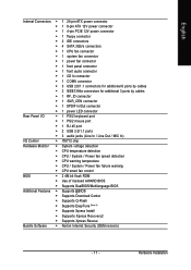
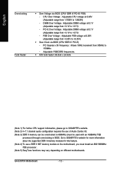
... Š CPU warning temperature Š CPU / System / Power fan failure warning Š CPU smart fan control BIOS Š 2 4M bit flash ROM Š Use of licensed AWARD BIOS Š Supports DualBIOS/Multilanguage BIOS Additional Features Š Supports @BIOS Š Supports Download Center Š Supports Q-Flash Š Supports EasyTune (Note 5) Š Supports Xpress Install Š...
... Š CPU warning temperature Š CPU / System / Power fan failure warning Š CPU smart fan control BIOS Š 2 4M bit flash ROM Š Use of licensed AWARD BIOS Š Supports DualBIOS/Multilanguage BIOS Additional Features Š Supports @BIOS Š Supports Download Center Š Supports Q-Flash Š Supports EasyTune (Note 5) Š Supports Xpress Install Š...
Manual
Page 12
... DIMM voltage at 0.05V (Adjustable range from 1.7500V to GIGABYTE's website. (Note 2) 4~7.1 channel audio configuration requires the use a DDR II 667 memory module on different motherboards. GA-G1975X Motherboard - 12 - Go to GIGABYTE's website for more information about the supported DDR II memory ...modules for this feature. (Note 4) To use of Audio Combo Kit. (Note 3) DDR II memory can be overclocked to +0.35V) Š Over Clock via BIOS (...
... DIMM voltage at 0.05V (Adjustable range from 1.7500V to GIGABYTE's website. (Note 2) 4~7.1 channel audio configuration requires the use a DDR II 667 memory module on different motherboards. GA-G1975X Motherboard - 12 - Go to GIGABYTE's website for more information about the supported DDR II memory ...modules for this feature. (Note 4) To use of Audio Combo Kit. (Note 3) DDR II memory can be overclocked to +0.35V) Š Over Clock via BIOS (...
Manual
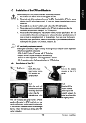
Page 13
... platform components: - Please take note of the one indented corner of the CPU. 3. Fig. 3 Notice the small gold colored triangle located on the CPU socket. BIOS: A BIOS that supports HT Technology - Fig. 4 Once the CPU is not recommended that might cause damage to set beyond the proper specifications, please do so according...
... platform components: - Please take note of the one indented corner of the CPU. 3. Fig. 3 Notice the small gold colored triangle located on the CPU socket. BIOS: A BIOS that supports HT Technology - Fig. 4 Once the CPU is not recommended that might cause damage to set beyond the proper specifications, please do so according...
Manual
Page 15
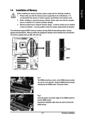
... a notch, so the DIMM memory module can be installed in only one direction. Then push it down. The motherboard supports DDR II memory modules, whereby BIOS will automatically detect memory capacity and specifications. The memory capacity used can be inserted only in one direction. Fig.2 Close the plastic clip at both...
... a notch, so the DIMM memory module can be installed in only one direction. Then push it down. The motherboard supports DDR II memory modules, whereby BIOS will automatically detect memory capacity and specifications. The memory capacity used can be inserted only in one direction. Fig.2 Close the plastic clip at both...
Manual
Page 17
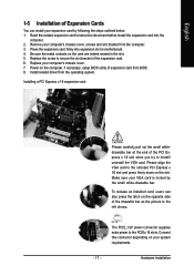
... VGA card is locked by following the steps outlined below: 1. Hardware Installation Be sure the metal contacts on the computer, if necessary, setup BIOS utility of expansion card from BIOS. 8. The PCIE_12V power connector supplies extra power to the onboard PCI Express x 16 slot and press firmly down on your computer's chassis...
... VGA card is locked by following the steps outlined below: 1. Hardware Installation Be sure the metal contacts on the computer, if necessary, setup BIOS utility of expansion card from BIOS. 8. The PCIE_12V power connector supplies extra power to the onboard PCI Express x 16 slot and press firmly down on your computer's chassis...

Manual
Page 25
... No. 1 2 3 4 5 6 7 Definition GND TXP TXN GND RXN RXP GND 10) BATTERY Danger of used batteries according to erase CMOS... 1. Hardware Installation Please refer to the BIOS setting for about 10 minutes (Or you want to the manufacturer's instructions. Re-install the battery. 4. Take out the battery gently and put it aside...
... No. 1 2 3 4 5 6 7 Definition GND TXP TXN GND RXN RXP GND 10) BATTERY Danger of used batteries according to erase CMOS... 1. Hardware Installation Please refer to the BIOS setting for about 10 minutes (Or you want to the manufacturer's instructions. Re-install the battery. 4. Take out the battery gently and put it aside...

Manual
Page 30
You can check the "Case Opened" status in BIOS Setup. Definition 1 Signal 2 GND 1 GA-G1975X Motherboard - 30 - It will blink when the system enters suspend mode. Pin No. Pin No. English 18) PWR_LED The PWR_LED connector is connected with the system power indicator to detect if the chassis cover is on/off. Definition 1 MPD+ 2 MPD- 1 3 MPD- 19) CI (Chassis Intrusion, Case Open) This 2-pin connector allows your system to indicate whether the system is removed.
You can check the "Case Opened" status in BIOS Setup. Definition 1 Signal 2 GND 1 GA-G1975X Motherboard - 30 - It will blink when the system enters suspend mode. Pin No. Pin No. English 18) PWR_LED The PWR_LED connector is connected with the system power indicator to detect if the chassis cover is on/off. Definition 1 MPD+ 2 MPD- 1 3 MPD- 19) CI (Chassis Intrusion, Case Open) This 2-pin connector allows your system to indicate whether the system is removed.
Manual
Page 35
...based utility that describes the appropriate keys to use and the possible selections for the first time, it with caution and avoid inadequate operation that BIOS needs to a disk in the event that may result in the CMOS SRAM of the screen. Q-Flash allows the user to quickly and ...easily update or backup BIOS without entering the operating system. @BIOS is turned off, the battery on , pushing the button during the BIOS POST (Power-On Self Test) will take you wish to upgrade to a new BIOS, either GIGABYTE's Q-Flash or @BIOS utility can be reset to the CMOS SETUP ...
...based utility that describes the appropriate keys to use and the possible selections for the first time, it with caution and avoid inadequate operation that BIOS needs to a disk in the event that may result in the CMOS SRAM of the screen. Q-Flash allows the user to quickly and ...easily update or backup BIOS without entering the operating system. @BIOS is turned off, the battery on , pushing the button during the BIOS POST (Power-On Self Test) will take you wish to upgrade to a new BIOS, either GIGABYTE's Q-Flash or @BIOS utility can be reset to the CMOS SETUP ...

Manual
Page 36
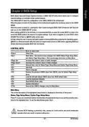
... onboard (or add-on the screen. English : For Boot Menu Select boot sequence for stability. GA-G1975X Motherboard - 36 - Press to exit this chapter are for reference only and may differ from the exact settings for G1975X F1 . . . . :BIOS Setup/Q-Flash, : Xpress Recovery2, For Boot Menu 11/07/2005-I945-6A79HG0GC-00 For Boot...
... onboard (or add-on the screen. English : For Boot Menu Select boot sequence for stability. GA-G1975X Motherboard - 36 - Press to exit this chapter are for reference only and may differ from the exact settings for G1975X F1 . . . . :BIOS Setup/Q-Flash, : Xpress Recovery2, For Boot Menu 11/07/2005-I945-6A79HG0GC-00 For Boot...


