
User Manual
Page 2
... prior notice. Example: Disclaimer Information in this manual is protected by GIGABYTE without GIGABYTE's prior written permission. „„ In order to the specifications and features in this : "REV: X.X." Check your motherboard looks like this manual are legally registered to their respective owners. Motherboard GA-F2A75M-HD2 Motherboard GA-F2A75M-HD2 Sept. 2, 2013 Sept. 2, 2013 Copyright © 2013 GIGA-BYTE TECHNOLOGY...
... prior notice. Example: Disclaimer Information in this manual is protected by GIGABYTE without GIGABYTE's prior written permission. „„ In order to the specifications and features in this : "REV: X.X." Check your motherboard looks like this manual are legally registered to their respective owners. Motherboard GA-F2A75M-HD2 Motherboard GA-F2A75M-HD2 Sept. 2, 2013 Sept. 2, 2013 Copyright © 2013 GIGA-BYTE TECHNOLOGY...
User Manual
Page 3
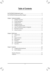
Table of Contents GA-F2A75M-HD2 Motherboard Layout 4 GA-F2A75M-HD2 Motherboard Block Diagram 5 Chapter 1 Hardware Installation 6 1-1 Installation Precautions 6 1-2 Product Specifications 7 1-3 Installing the APU 9 1-4 Installing the Memory 9 1-5 Installing an Expansion Card 10 1-6 Setup of the AMD Dual ...
Table of Contents GA-F2A75M-HD2 Motherboard Layout 4 GA-F2A75M-HD2 Motherboard Block Diagram 5 Chapter 1 Hardware Installation 6 1-1 Installation Precautions 6 1-2 Product Specifications 7 1-3 Installing the APU 9 1-4 Installing the Memory 9 1-5 Installing an Expansion Card 10 1-6 Setup of the AMD Dual ...

User Manual
Page 4
...shall depend on the product package you obtain. GA-F2A75M-HD2 Motherboard Layout KB_MS_USB VGA ATX_12V Socket FM2+ ATX DVI HDMI CPU_FAN USB30_LAN CI DDR3_2 DDR3_1 SATA3 AUDIO Realtek® GbE LAN BAT 2 SYS_FAN 3 PCIEX16 GA-F2A75M-HD2 iTE® Super I/O PCIEX1 PCI CODEC ...F_AUDIO M_BIOS B_BIOS AMD A75 CLR_CMOS F_USB30 SATA3 0 1 COM F_USB1 Box Contents SPDIF_O F_USB2 F_PANEL 55 GA-F2A75M-HD2 motherboard 55 Motherboard driver disk 55 Two SATA cables 55 User's ...
...shall depend on the product package you obtain. GA-F2A75M-HD2 Motherboard Layout KB_MS_USB VGA ATX_12V Socket FM2+ ATX DVI HDMI CPU_FAN USB30_LAN CI DDR3_2 DDR3_1 SATA3 AUDIO Realtek® GbE LAN BAT 2 SYS_FAN 3 PCIEX16 GA-F2A75M-HD2 iTE® Super I/O PCIEX1 PCI CODEC ...F_AUDIO M_BIOS B_BIOS AMD A75 CLR_CMOS F_USB30 SATA3 0 1 COM F_USB1 Box Contents SPDIF_O F_USB2 F_PANEL 55 GA-F2A75M-HD2 motherboard 55 Motherboard driver disk 55 Two SATA cables 55 User's ...

User Manual
Page 5
GA-F2A75M-HD2 Motherboard Block Diagram 1 PCI Express x16 PCIe CLK (100 MHz) PCI Express Bus LAN RJ45 Realtek® GbE LAN x16 x1 x1 AMD APU APU CLK+/- (...
GA-F2A75M-HD2 Motherboard Block Diagram 1 PCI Express x16 PCIe CLK (100 MHz) PCI Express Bus LAN RJ45 Realtek® GbE LAN x16 x1 x1 AMD APU APU CLK+/- (...

User Manual
Page 6
...wear an electrostatic discharge (ESD) wrist strap when handling electronic components such as a motherboard, APU or memory. Chapter 1 Hardware Installation 1-1 Installation Precautions The motherboard contains numerous delicate electronic circuits and components which can lead to damage to system components ... shielding container. •• Before unplugging the power supply cable from the power outlet before installing or removing the motherboard or other hardware components. •• When connecting hardware components to the internal connectors on the power, make sure...
...wear an electrostatic discharge (ESD) wrist strap when handling electronic components such as a motherboard, APU or memory. Chapter 1 Hardware Installation 1-1 Installation Precautions The motherboard contains numerous delicate electronic circuits and components which can lead to damage to system components ... shielding container. •• Before unplugging the power supply cable from the power outlet before installing or removing the motherboard or other hardware components. •• When connecting hardware components to the internal connectors on the power, make sure...

User Manual
Page 8
... Support for ON/OFF Charge Norton® Internet Security (OEM version) - 8 - Support for Smart Recovery 2 Support for EasyTune * Available functions in EasyTune may differ by motherboard model.
... Support for ON/OFF Charge Norton® Internet Security (OEM version) - 8 - Support for Smart Recovery 2 Support for EasyTune * Available functions in EasyTune may differ by motherboard model.

User Manual
Page 9
...the pin one direction. After the memory is installed, the BIOS will double the original memory bandwidth. - 9 - Dual Channel Memory Configuration This motherboard provides two DDR3 memory sockets and supports Dual Channel Technology. Operating System Form Factor Š Support for Windows 8.1/8/7 32-bit/64-bit * ...unplug the power cord from the power outlet before you begin to install the APU: •• Make sure that the motherboard supports the APU. (Go to GIGABYTE's website for the latest APU support list.) •• Always turn on the surface of the APU. ••...
...the pin one direction. After the memory is installed, the BIOS will double the original memory bandwidth. - 9 - Dual Channel Memory Configuration This motherboard provides two DDR3 memory sockets and supports Dual Channel Technology. Operating System Form Factor Š Support for Windows 8.1/8/7 32-bit/64-bit * ...unplug the power cord from the power outlet before you begin to install the APU: •• Make sure that the motherboard supports the APU. (Go to GIGABYTE's website for the latest APU support list.) •• Always turn on the surface of the APU. ••...

User Manual
Page 10
... A. Step 2: Enter BIOS Setup to 512M or above ) -- Restart your computer. System Requirements -- An AMD Dual Graphics technology-supported motherboard (with your expansion card. •• Always turn off the computer and unplug the power cord from the power outlet before installing an...enabled if only one memory socket as following guidelines before you begin to install an expansion card: •• Make sure the motherboard supports the expansion card. Set UMA Frame Buffer Size to set the following guidelines before installing the memory in Dual Channel mode....
... A. Step 2: Enter BIOS Setup to 512M or above ) -- Restart your computer. System Requirements -- An AMD Dual Graphics technology-supported motherboard (with your expansion card. •• Always turn off the computer and unplug the power cord from the power outlet before installing an...enabled if only one memory socket as following guidelines before you begin to install an expansion card: •• Make sure the motherboard supports the expansion card. Set UMA Frame Buffer Size to set the following guidelines before installing the memory in Dual Channel mode....

User Manual
Page 11
... HDCP compliant and supports Dolby True HD and DTS HD Master Audio formats. Connect a monitor that the actual resolutions supported are supported after you install motherboard drivers in OS. A. DVI-D Port (Note 1) The DVI-D port conforms to connect a PS/2 mouse or keyboard. PS/2 Keyboard/Mouse Port Use this port to the...
... HDCP compliant and supports Dolby True HD and DTS HD Master Audio formats. Connect a monitor that the actual resolutions supported are supported after you install motherboard drivers in OS. A. DVI-D Port (Note 1) The DVI-D port conforms to connect a PS/2 mouse or keyboard. PS/2 Keyboard/Mouse Port Use this port to the...
User Manual
Page 12
... device and then remove it from the connector. Line Out Jack (Green) The default line out jack. Do not rock it straight out from the motherboard. •• When removing the cable, pull it side to side to connect front speakers in jack. Use this audio jack for USB devices such...
... device and then remove it from the connector. Line Out Jack (Green) The default line out jack. Do not rock it straight out from the motherboard. •• When removing the cable, pull it side to side to connect front speakers in jack. Use this audio jack for USB devices such...

User Manual
Page 13
... sure your devices are compliant with the connectors you wish to connect. •• Before installing the devices, be sure to the connector on the motherboard. - 13 -
... sure your devices are compliant with the connectors you wish to connect. •• Before installing the devices, be sure to the connector on the motherboard. - 13 -

User Manual
Page 14
If a power supply is used (500W or greater). For optimum heat dissipation, it is turned off and all the components on the motherboard. Definition 12 24 1 3.3V Pin No. The speed control function requires the use of a fan with fan speed control design. Definition 1 GND 2 +...12V 3 Sense 4 Speed Control 1 SYS_FAN SYS_FAN: Pin No. Do not place a jumper cap on this motherboard are 4-pin. Before connecting the power connector, first make sure the power supply is recommended that a power supply that a system fan be sure to an...
If a power supply is used (500W or greater). For optimum heat dissipation, it is turned off and all the components on the motherboard. Definition 12 24 1 3.3V Pin No. The speed control function requires the use of a fan with fan speed control design. Definition 1 GND 2 +...12V 3 Sense 4 Speed Control 1 SYS_FAN SYS_FAN: Pin No. Do not place a jumper cap on this motherboard are 4-pin. Before connecting the power connector, first make sure the power supply is recommended that a power supply that a system fan be sure to an...

User Manual
Page 15
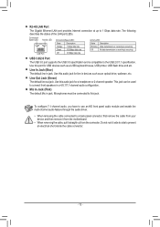
... panel design may NC RES+ RESHD- For example, some graphics cards may require you to use a S/PDIF digital audio cable for your motherboard to the power status indicator on the chassis front panel. For information about connecting the S/PDIF digital audio cable, carefully read the manual for... digital audio output from your motherboard to your graphics card if you wish to connect an HDMI display to the graphics card and have digital audio output from your expansion...
... panel design may NC RES+ RESHD- For example, some graphics cards may require you to use a S/PDIF digital audio cable for your motherboard to the power status indicator on the chassis front panel. For information about connecting the S/PDIF digital audio cable, carefully read the manual for... digital audio output from your motherboard to your graphics card if you wish to connect an HDMI display to the graphics card and have digital audio output from your expansion...
User Manual
Page 16
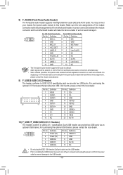
... on each wire instead of a single plug. Each USB header can provide two USB ports. Incorrect connection between the module connector and the motherboard header will be sure to turn off your chassis front panel audio module to USB 3.0/2.0 specification and can provide two USB ports via an... your computer and unplug the power cord from the power outlet to prevent damage to installing the USB bracket, be present on both of the motherboard header. Definition 1 9 1 10 2 1 Power (5V) 6 USB DY+ _S 2 Power (5V) 7 GND 3 USB DX- 8 GND 4 USB DY- 9 No Pin 5 USB DX+ 10 NC S 1 23 ...
... on each wire instead of a single plug. Each USB header can provide two USB ports. Incorrect connection between the module connector and the motherboard header will be sure to turn off your chassis front panel audio module to USB 3.0/2.0 specification and can provide two USB ports via an... your computer and unplug the power cord from the power outlet to prevent damage to installing the USB bracket, be present on both of the motherboard header. Definition 1 9 1 10 2 1 Power (5V) 6 USB DY+ _S 2 Power (5V) 7 GND 3 USB DX- 8 GND 4 USB DY- 9 No Pin 5 USB DX+ 10 NC S 1 23 ...

User Manual
Page 17
... place of purchase or local dealer if you are not able to touch the two pins for BIOS configurations). 13) CI (Chassis Intrusion Header) This motherboard provides a chassis detection feature that detects if the chassis cover has been removed. 11) COM (Serial Port Header) The COM header can provide one serial...
... place of purchase or local dealer if you are not able to touch the two pins for BIOS configurations). 13) CI (Chassis Intrusion Header) This motherboard provides a chassis detection feature that detects if the chassis cover has been removed. 11) COM (Serial Port Header) The COM header can provide one serial...

User Manual
Page 18
...is potentially risky, if you do it with caution. Inadequate BIOS flashing may differ by BIOS version. - 18 - Or you can use either the GIGABYTE Q-Flash or @BIOS utility. •• Q-Flash allows the user to quickly and easily upgrade or back up BIOS without entering the operating system. ... Its major functions include conducting the Power-On Self-Test (POST) during the POST when the power is turned off, the battery on the motherboard supplies the necessary power to the CMOS to accept or enter a sub-menu. To upgrade the BIOS, use your system to prevent system instability...
...is potentially risky, if you do it with caution. Inadequate BIOS flashing may differ by BIOS version. - 18 - Or you can use either the GIGABYTE Q-Flash or @BIOS utility. •• Q-Flash allows the user to quickly and easily upgrade or back up BIOS without entering the operating system. ... Its major functions include conducting the Power-On Self-Test (POST) during the POST when the power is turned off, the battery on the motherboard supplies the necessary power to the CMOS to accept or enter a sub-menu. To upgrade the BIOS, use your system to prevent system instability...
User Manual
Page 21
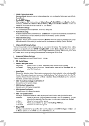
... reset the board to default values by loading optimized defaults or clearing the CMOS values. `` Advanced Voltage Settings This sub-menu allows you to the motherboard CI header. Enabled allows the system to simultaneously access different channels of previous chassis intrusion status and the Case Open field will show "No". The...
... reset the board to default values by loading optimized defaults or clearing the CMOS values. `` Advanced Voltage Settings This sub-menu allows you to the motherboard CI header. Enabled allows the system to simultaneously access different channels of previous chassis intrusion status and the Case Open field will show "No". The...

User Manual
Page 22
You can adjust the fan speed with EasyTune based on your motherboard model and BIOS version. The time format is week (read-only), month, date, and year. && System Fan Speed Control Allows you to determine whether to ...
You can adjust the fan speed with EasyTune based on your motherboard model and BIOS version. The time format is week (read-only), month, date, and year. && System Fan Speed Control Allows you to determine whether to ...
User Manual
Page 29
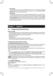
... differ from your computer Attach one hard drive. •• Windows 8/7(32-bit/64-bit), Windows Vista/XP (32-bit) setup disk. •• Motherboard driver disk. •• A USB flash drive. •• A USB floppy disk drive (needed during Windows XP installation). •• An empty...mode correctly in "C-1." Press to configure UEFI RAID, follow the steps in system BIOS Setup. If you will see shall depend on the motherboard. The actual BIOS Setup menu options you want to complete. To enter the legacy RAID ROM, save as reverting the BIOS settings to ...
... differ from your computer Attach one hard drive. •• Windows 8/7(32-bit/64-bit), Windows Vista/XP (32-bit) setup disk. •• Motherboard driver disk. •• A USB flash drive. •• A USB floppy disk drive (needed during Windows XP installation). •• An empty...mode correctly in "C-1." Press to configure UEFI RAID, follow the steps in system BIOS Setup. If you will see shall depend on the motherboard. The actual BIOS Setup menu options you want to complete. To enter the legacy RAID ROM, save as reverting the BIOS settings to ...

User Manual
Page 31
.../AHCI driver. To copy the RAID/AHCI driver for Windows 8, copy the whole Hw8_A85 folder under the BootDrv folder in the motherboard driver disk to your computer first because you will install all files in the \BootDrv\Hxp folder in the...Browse. Installing Windows 8/7/Vista (The following instructions use Windows 8 as the example operating system.) •• After installing the operating system, insert the motherboard driver disk into your operating system. You can proceed with this option. 7. Installing the SATA RAID/AHCI Driver and Operating System A. When the screen ...
.../AHCI driver. To copy the RAID/AHCI driver for Windows 8, copy the whole Hw8_A85 folder under the BootDrv folder in the motherboard driver disk to your computer first because you will install all files in the \BootDrv\Hxp folder in the...Browse. Installing Windows 8/7/Vista (The following instructions use Windows 8 as the example operating system.) •• After installing the operating system, insert the motherboard driver disk into your operating system. You can proceed with this option. 7. Installing the SATA RAID/AHCI Driver and Operating System A. When the screen ...


