Manual
Page 4
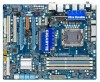
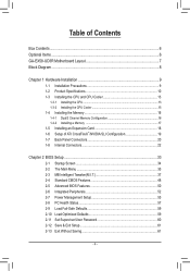
Table of Contents Box Contents...6 Optional Items...6 GA-EX58-UD3R Motherboard Layout 7 Block Diagram...8 Chapter 1 Hardware Installation 9 1-1 Installation Precautions 9 1-2 Product Specifications 10 1-3 Installing the CPU and CPU Cooler 13 ...Installing the Memory 16 1-4-1 Dual/3 Channel Memory Configuration 16 1-4-2 Installing a Memory 17 1-5 Installing an Expansion Card 18 1-6 Setup of ATI CrossFireX™/NVIDIA SLI Configuration 19 1-7 Back Panel Connectors 20 1-8 Internal Connectors 22 Chapter 2 BIOS Setup 33 2-1 Startup Screen 34 2-2 The Main Menu 35 2-3 MB Intelligent...
Table of Contents Box Contents...6 Optional Items...6 GA-EX58-UD3R Motherboard Layout 7 Block Diagram...8 Chapter 1 Hardware Installation 9 1-1 Installation Precautions 9 1-2 Product Specifications 10 1-3 Installing the CPU and CPU Cooler 13 ...Installing the Memory 16 1-4-1 Dual/3 Channel Memory Configuration 16 1-4-2 Installing a Memory 17 1-5 Installing an Expansion Card 18 1-6 Setup of ATI CrossFireX™/NVIDIA SLI Configuration 19 1-7 Back Panel Connectors 20 1-8 Internal Connectors 22 Chapter 2 BIOS Setup 33 2-1 Startup Screen 34 2-2 The Main Menu 35 2-3 MB Intelligent...
Manual
Page 6
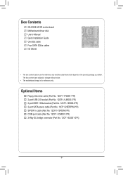
Box Contents GA-EX58-UD3R motherboard Motherboard driver disk User's Manual Quick Installation Guide One IDE cable Four SATA 3Gb/s cables I/O Shield • The box contents above are subject to .... 12CF1-1IE008-0*R) 2-port SATA power cable (Part No. 12CF1-2SERPW-0*R) S/PDIF In cable (Part No. 12CR1-1SPDIN-0*R) COM port cable (Part No. 12CF1-1CM001-3*R) 2-Way SLI bridge connector (Part No. 12CF1-SLI001-0*R) - 6 -
Box Contents GA-EX58-UD3R motherboard Motherboard driver disk User's Manual Quick Installation Guide One IDE cable Four SATA 3Gb/s cables I/O Shield • The box contents above are subject to .... 12CF1-1IE008-0*R) 2-port SATA power cable (Part No. 12CF1-2SERPW-0*R) S/PDIF In cable (Part No. 12CR1-1SPDIN-0*R) COM port cable (Part No. 12CF1-1CM001-3*R) 2-Way SLI bridge connector (Part No. 12CF1-SLI001-0*R) - 6 -
Manual
Page 10
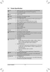
...4 via the IEEE 1394a bracket connected to 6 SATA 3Gb/s devices - Support for SATA RAID 0, RAID 1, RAID 5 and RAID 10 GIGABYTE SATA2 chip: - 1 x IDE connector supporting ATA-133/100/66/33 and up to 2 IDE devices - 2 x SATA 3Gb/s connectors (GSATA2_0,.../1000 Mbit) Expansion Slots 2 x PCI Express x16 slots, running at x16 (The PCI Express x16 slots support ATI CrossFireX™/NVIDIA SLI technology and conform to PCI Express 2.0 standard 1 x PCI Express x4 slot 2 x PCI Express x1 slots 2 x PCI...
...4 via the IEEE 1394a bracket connected to 6 SATA 3Gb/s devices - Support for SATA RAID 0, RAID 1, RAID 5 and RAID 10 GIGABYTE SATA2 chip: - 1 x IDE connector supporting ATA-133/100/66/33 and up to 2 IDE devices - 2 x SATA 3Gb/s connectors (GSATA2_0,.../1000 Mbit) Expansion Slots 2 x PCI Express x16 slots, running at x16 (The PCI Express x16 slots support ATI CrossFireX™/NVIDIA SLI technology and conform to PCI Express 2.0 standard 1 x PCI Express x4 slot 2 x PCI Express x1 slots 2 x PCI...
Manual
Page 19
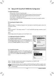
...by graphics cards. A power supply with two PCI Express x16 slots and correct driver - Hardware Installation System Requirements - A CrossFireX/SLI-supported motherboard with sufficient power is selected. Configuring the Graphics Card Driver C-1. Step 3: Plug the display cable into the graphics ...card on the PCI Express x16 slots. Two CrossFire (Note 1)/SLI bridge connectors (Note 2) - Windows Vista or Windows XP operating system - Connecting the Graphics Cards Step 1: Observe the steps ...
...by graphics cards. A power supply with two PCI Express x16 slots and correct driver - Hardware Installation System Requirements - A CrossFireX/SLI-supported motherboard with sufficient power is selected. Configuring the Graphics Card Driver C-1. Step 3: Plug the display cable into the graphics ...card on the PCI Express x16 slots. Two CrossFire (Note 1)/SLI bridge connectors (Note 2) - Windows Vista or Windows XP operating system - Connecting the Graphics Cards Step 1: Observe the steps ...


