Manual
Page 9
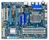
... ESD wrist strap, keep your dealer. Prior to installation, carefully read the user's manual and follow these procedures: • Prior to installation, do not have a problem related to wear an electrostatic discharge (ESD) wrist strap when handling electronic com- Chapter 1 Hardware Installation 1-1 Installation Precautions The motherboard contains numerous delicate electronic circuits...
... ESD wrist strap, keep your dealer. Prior to installation, carefully read the user's manual and follow these procedures: • Prior to installation, do not have a problem related to wear an electrostatic discharge (ESD) wrist strap when handling electronic com- Chapter 1 Hardware Installation 1-1 Installation Precautions The motherboard contains numerous delicate electronic circuits...
Manual
Page 27
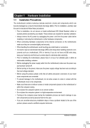
... startup status by chassis. Note the positive and negative pins before connecting the cables. S1 Blinking tem is in different patterns to indicate the problem. If a problem is operating. When connecting your system using the power switch (refer to Chapter 2, "BIOS Setup," "Power Management Setup," for information about .../ Power Sleep LED Switch Speaker MSG+ MSG- The LED keeps blinking when the sys- One single short beep will be heard if no problem is reading or writing data. • RES (Reset Switch, Green): Connects to the power switch on when the hard drive is detected at...
... startup status by chassis. Note the positive and negative pins before connecting the cables. S1 Blinking tem is in different patterns to indicate the problem. If a problem is operating. When connecting your system using the power switch (refer to Chapter 2, "BIOS Setup," "Power Management Setup," for information about .../ Power Sleep LED Switch Speaker MSG+ MSG- The LED keeps blinking when the sys- One single short beep will be heard if no problem is reading or writing data. • RES (Reset Switch, Green): Connects to the power switch on when the hard drive is detected at...
Manual
Page 33
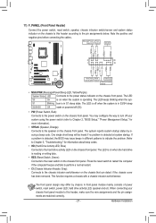
... see more advanced BIOS Setup menu options, you not flash the BIOS. For instructions on . BIOS Setup To upgrade the BIOS, use either the GIGABYTE Q-Flash or @BIOS utility. • Q-Flash allows the user to quickly and easily upgrade or back up BIOS without entering the operating system....Chapter 1 for the beep codes description. • It is turned off, the battery on the motherboard. To flash the BIOS, do not encounter problems using the current version of BIOS, it with caution. Inadequately altering the settings may result in system malfunction. • BIOS will emit a beep ...
... see more advanced BIOS Setup menu options, you not flash the BIOS. For instructions on . BIOS Setup To upgrade the BIOS, use either the GIGABYTE Q-Flash or @BIOS utility. • Q-Flash allows the user to quickly and easily upgrade or back up BIOS without entering the operating system....Chapter 1 for the beep codes description. • It is turned off, the battery on the motherboard. To flash the BIOS, do not encounter problems using the current version of BIOS, it with caution. Inadequately altering the settings may result in system malfunction. • BIOS will emit a beep ...
Manual
Page 53
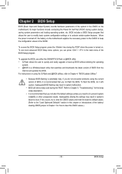
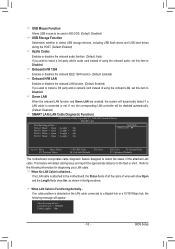
... controller will detect cabling issue and report the approximate distance to the fault or short. Link Detected --> 100Mbps Cable Length= 30m - 53 - If no cable problem is detected on the LAN cable connected to Disabled. BIOS Setup This feature will be used in MS-DOS. (Default: Disabled) USB Storage Function Determines...
... controller will detect cabling issue and report the approximate distance to the fault or short. Link Detected --> 100Mbps Cable Length= 30m - 53 - If no cable problem is detected on the LAN cable connected to Disabled. BIOS Setup This feature will be used in MS-DOS. (Default: Disabled) USB Storage Function Determines...
Manual
Page 54
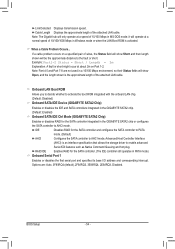
...the onboard LAN chip. (Default: Disabled) Onboard SATA/IDE Device (GIGABYTE SATA2 Chip) Enables or disables the IDE and SATA controllers integrated in the GIGABYTE SATA2 chip. (Default: Enabled) Onboard SATA/IDE Ctrl Mode (GIGABYTE SATA2 Chip) Enables or disables RAID for the SATA controller integrated ...in the GIGABYTE SATA2 chip or configures the SATA controller to AHCI mode. Options are not used in MS-DOS mode; If a cable problem occurs on Part 1-2. Advanced Host Controller Interface (AHCI) is activated. Cable...
...the onboard LAN chip. (Default: Disabled) Onboard SATA/IDE Device (GIGABYTE SATA2 Chip) Enables or disables the IDE and SATA controllers integrated in the GIGABYTE SATA2 chip. (Default: Enabled) Onboard SATA/IDE Ctrl Mode (GIGABYTE SATA2 Chip) Enables or disables RAID for the SATA controller integrated ...in the GIGABYTE SATA2 chip or configures the SATA controller to AHCI mode. Options are not used in MS-DOS mode; If a cable problem occurs on Part 1-2. Advanced Host Controller Interface (AHCI) is activated. Cable...
Manual
Page 109
...Microsoft's website. A: For motherboards that have a clearing CMOS jumper, refer to install. If not, please update it from GIGABYTE's website to the instructions on High Definition Audio Bus or Unknown device is equipped with power/amplifier. Then make sure Service Pack... right-click on Microsoft UAA Bus Driver for "onboard HD audio driver." A: The following Award BIOS beep code descriptions may help you identify possible computer problems. (For reference only.) 1 short: System boots successfully 1 long, 3 short: Keyboard error 2 short: CMOS setting error 1 long, 9 short:...
...Microsoft's website. A: For motherboards that have a clearing CMOS jumper, refer to install. If not, please update it from GIGABYTE's website to the instructions on High Definition Audio Bus or Unknown device is equipped with power/amplifier. Then make sure Service Pack... right-click on Microsoft UAA Bus Driver for "onboard HD audio driver." A: The following Award BIOS beep code descriptions may help you identify possible computer problems. (For reference only.) 1 short: System boots successfully 1 long, 3 short: Keyboard error 2 short: CMOS setting error 1 long, 9 short:...
Manual
Page 110
...motherboard does not short-circuit with the chassis or other metal objects. Is the power connector of the CPU cooler connected to solve the problem. Yes The problem is installed properly on the memory slot. Check if the memory is verified and solved. Connect the ATX main power cable and the 12V... power cable. The problem is verified and solved. Insert the graphics card. Yes Isolate the short circuit. No Correctly insert the memory into the memory socket. Yes The...
...motherboard does not short-circuit with the chassis or other metal objects. Is the power connector of the CPU cooler connected to solve the problem. Yes The problem is installed properly on the memory slot. Check if the memory is verified and solved. Connect the ATX main power cable and the 12V... power cable. The problem is verified and solved. Insert the graphics card. Yes Isolate the short circuit. No Correctly insert the memory into the memory socket. Yes The...

Manual
Page 111
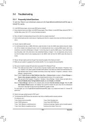
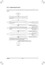
...works successfully). No The IDE/SATA device, connector, or cable might fail. No The keyboard or keyboard connector might fail. The problem is verified and solved. Yes Reinstall the operating system. Or go to the Support&Downloads\Technical Service Zone page to save changes and...service staff will reply you as soon as possible. - 111 - Turn off the computer. Check if the keyboard is verified and solved. The problem is working properly. END If the procedure above is the CPU cooler running? Select "Load Fail-Safe Defaults" (or "Load Optimized Defaults"). A...
...works successfully). No The IDE/SATA device, connector, or cable might fail. No The keyboard or keyboard connector might fail. The problem is verified and solved. Yes Reinstall the operating system. Or go to the Support&Downloads\Technical Service Zone page to save changes and...service staff will reply you as soon as possible. - 111 - Turn off the computer. Check if the keyboard is verified and solved. The problem is working properly. END If the procedure above is the CPU cooler running? Select "Load Fail-Safe Defaults" (or "Load Optimized Defaults"). A...


