Manual
Page 3
...carefully read or download the information on/from the Support&Downloads\Motherboard\Technology Guide page on your motherboard revision before updating motherboard BIOS, drivers, or when looking for technical information. Check your motherboard looks like this manual is protected by any form or by... copyright laws and is 1.0. Disclaimer Information in any means without prior notice. No part of GIGABYTE. Changes to use of this product, GIGABYTE provides the following types of documentations: For quick set-up of the motherboard is the property of this ...
...carefully read or download the information on/from the Support&Downloads\Motherboard\Technology Guide page on your motherboard revision before updating motherboard BIOS, drivers, or when looking for technical information. Check your motherboard looks like this manual is protected by any form or by... copyright laws and is 1.0. Disclaimer Information in any means without prior notice. No part of GIGABYTE. Changes to use of this product, GIGABYTE provides the following types of documentations: For quick set-up of the motherboard is the property of this ...
Manual
Page 4
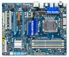
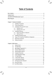
Table of Contents Box Contents...6 Optional Items...6 GA-EX58-UD3R Motherboard Layout 7 Block Diagram...8 Chapter 1 Hardware Installation 9 1-1 Installation Precautions 9 1-2 Product Specifications 10 1-3 Installing the CPU and CPU Cooler 13 1-3-1...8482;/NVIDIA SLI Configuration 19 1-7 Back Panel Connectors 20 1-8 Internal Connectors 22 Chapter 2 BIOS Setup 33 2-1 Startup Screen 34 2-2 The Main Menu 35 2-3 MB Intelligent Tweaker(M.I.T 37 2-4 Standard CMOS Features 48 2-5 Advanced BIOS Features 50 2-6 Integrated Peripherals 52 2-7 Power Management Setup 55 2-8 PC Health Status 57...
Table of Contents Box Contents...6 Optional Items...6 GA-EX58-UD3R Motherboard Layout 7 Block Diagram...8 Chapter 1 Hardware Installation 9 1-1 Installation Precautions 9 1-2 Product Specifications 10 1-3 Installing the CPU and CPU Cooler 13 1-3-1...8482;/NVIDIA SLI Configuration 19 1-7 Back Panel Connectors 20 1-8 Internal Connectors 22 Chapter 2 BIOS Setup 33 2-1 Startup Screen 34 2-2 The Main Menu 35 2-3 MB Intelligent Tweaker(M.I.T 37 2-4 Standard CMOS Features 48 2-5 Advanced BIOS Features 50 2-6 Integrated Peripherals 52 2-7 Power Management Setup 55 2-8 PC Health Status 57...

Manual
Page 5
... Download Center 66 Chapter 4 Unique Features 67 4-1 Xpress Recovery2 67 4-2 BIOS Update Utilities 70 4-2-1 Updating the BIOS with the Q-Flash Utility 70 4-2-2 Updating the BIOS with the @BIOS Utility 73 4-3 EasyTune 6...74 4-4 Dynamic Energy Saver Advanced 75 4-5 Q-Share......77 4-6 Time Repair...78 Chapter 5 Appendix...79 5-1 Configuring SATA Hard Drive(s 79 5-1-1 Configuring Intel ICH10R SATA Controllers 79 5-1-2 Configuring GIGABYTE...
... Download Center 66 Chapter 4 Unique Features 67 4-1 Xpress Recovery2 67 4-2 BIOS Update Utilities 70 4-2-1 Updating the BIOS with the Q-Flash Utility 70 4-2-2 Updating the BIOS with the @BIOS Utility 73 4-3 EasyTune 6...74 4-4 Dynamic Energy Saver Advanced 75 4-5 Q-Share......77 4-6 Time Repair...78 Chapter 5 Appendix...79 5-1 Configuring SATA Hard Drive(s 79 5-1-1 Configuring Intel ICH10R SATA Controllers 79 5-1-2 Configuring GIGABYTE...
Manual
Page 8
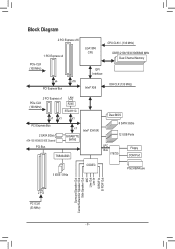
... RJ45 (100 MHz) RTL8111C x1 x1 x1 PCI Express Bus x1 2 SATA 3Gb/s ATA-133/100/66/33 IDE Channel PCI Bus GIGABYTE SATA2 TSB43AB23 Intel® ICH10R Dual BIOS 6 SATA 3Gb/s 12 USB Ports LPC Bus IT8720 Floppy COM Port 3 IEEE 1394a CODEC PS/2 KB/Mouse Surround Speaker Out Center/Subwoofer...
... RJ45 (100 MHz) RTL8111C x1 x1 x1 PCI Express Bus x1 2 SATA 3Gb/s ATA-133/100/66/33 IDE Channel PCI Bus GIGABYTE SATA2 TSB43AB23 Intel® ICH10R Dual BIOS 6 SATA 3Gb/s 12 USB Ports LPC Bus IT8720 Floppy COM Port 3 IEEE 1394a CODEC PS/2 KB/Mouse Surround Speaker Out Center/Subwoofer...
Manual
Page 12
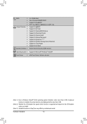
... Features w w w w w w w w w w Bundled Software w 2 x 16 Mbit flash Use of licensed AWARD BIOS Support for DualBIOS™ PnP 1.0a, DMI 2.0, SM BIOS 2.4, ACPI 1.0b Support for @BIOS Support for Q-Flash Support for Xpress BIOS Rescue Support for Download Center Support for Xpress Install Support for Xpress Recovery2 Support for EasyTune (Note 3) Support for Dynamic Energy Saver...
... Features w w w w w w w w w w Bundled Software w 2 x 16 Mbit flash Use of licensed AWARD BIOS Support for DualBIOS™ PnP 1.0a, DMI 2.0, SM BIOS 2.4, ACPI 1.0b Support for @BIOS Support for Q-Flash Support for Xpress BIOS Rescue Support for Download Center Support for Xpress Install Support for Xpress Recovery2 Support for EasyTune (Note 3) Support for Dynamic Energy Saver...
Manual
Page 16
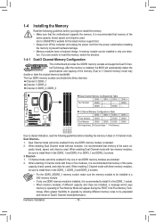
... • If only one DDR3 memory module is recommended that memory of the same capacity, brand, speed, and chips be used . (Go to GIGABYTE's website for the latest memory support list.) • Always turn off the computer and unplug the power cord from the power outlet before installing the... memory to install it is installed, the BIOS will appear during the POST. If you begin to install the memory: • Make sure that memory of different capacity and chips are installed....
... • If only one DDR3 memory module is recommended that memory of the same capacity, brand, speed, and chips be used . (Go to GIGABYTE's website for the latest memory support list.) • Always turn off the computer and unplug the power cord from the power outlet before installing the... memory to install it is installed, the BIOS will appear during the POST. If you begin to install the memory: • Make sure that memory of different capacity and chips are installed....
Manual
Page 18
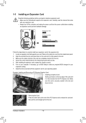
... Graphics Card: Gently push down on your operating system. Remove the metal slot cover from the power outlet before you begin to make any required BIOS changes for your card. Make sure the metal contacts on the top edge of the PCI Express slot to release the card and then pull...the chassis back panel with the slot, and press down on the card are completely inserted into the PCI Express slot. If necessary, go to BIOS Setup to install an expansion card: • Make sure the motherboard supports the expansion card. Locate an expansion slot that came with the expansion ...
... Graphics Card: Gently push down on your operating system. Remove the metal slot cover from the power outlet before you begin to make any required BIOS changes for your card. Make sure the metal contacts on the top edge of the PCI Express slot to release the card and then pull...the chassis back panel with the slot, and press down on the card are completely inserted into the PCI Express slot. If necessary, go to BIOS Setup to install an expansion card: • Make sure the motherboard supports the expansion card. Locate an expansion slot that came with the expansion ...
Manual
Page 27
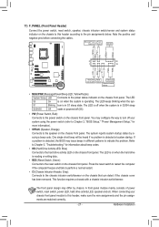
...power switch, reset switch, power LED, hard drive activity LED, speaker and etc. When connecting your system using the power switch (refer to Chapter 2, "BIOS Setup," "Power Management Setup," for information about beep codes. • HD (Hard Drive Activity LED, Blue) Connects to indicate the problem. The LED... the cables. PW+ PWSPEAK+ SPEAK- 2 20 1 19 HD+ HD- One single short beep will be heard if no problem is detected, the BIOS may configure the way to turn off (S5). • PW (Power Switch, Red): Connects to the reset switch on the chassis front panel. You...
...power switch, reset switch, power LED, hard drive activity LED, speaker and etc. When connecting your system using the power switch (refer to Chapter 2, "BIOS Setup," "Power Management Setup," for information about beep codes. • HD (Hard Drive Activity LED, Blue) Connects to indicate the problem. The LED... the cables. PW+ PWSPEAK+ SPEAK- 2 20 1 19 HD+ HD- One single short beep will be heard if no problem is detected, the BIOS may configure the way to turn off (S5). • PW (Power Switch, Red): Connects to the reset switch on the chassis front panel. You...
Manual
Page 31
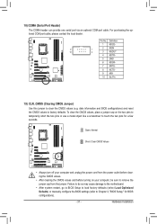
... NSOUT 4 NDTR- 5 GND 6 NDSR- 7 NRTS- 8 NCTS- 9 NRI- 10 No Pin 19) CLR_CMOS (Clearing CMOS Jumper) Use this jumper to Chapter 2, "BIOS Setup," for a few seconds. Hardware Installation To clear the CMOS values, place a jumper cap on your computer and unplug the power cord from the power...factory defaults (select Load Optimized Defaults) or manually configure the BIOS settings (refer to clear the CMOS values (e.g. date information and BIOS configurations) and reset the CMOS values to touch the two pins for BIOS configurations). - 31 - Open: Normal Short: Clear CMOS ...
... NSOUT 4 NDTR- 5 GND 6 NDSR- 7 NRTS- 8 NCTS- 9 NRI- 10 No Pin 19) CLR_CMOS (Clearing CMOS Jumper) Use this jumper to Chapter 2, "BIOS Setup," for a few seconds. Hardware Installation To clear the CMOS values, place a jumper cap on your computer and unplug the power cord from the power...factory defaults (select Load Optimized Defaults) or manually configure the BIOS settings (refer to clear the CMOS values (e.g. date information and BIOS configurations) and reset the CMOS values to touch the two pins for BIOS configurations). - 31 - Open: Normal Short: Clear CMOS ...
Manual
Page 32
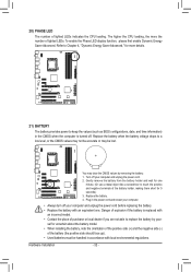
... the battery: 1. Hardware Installation - 32 - The higher the CPU loading, the more details. 21) BATTERY The battery provides power to keep the values (such as BIOS configurations, date, and time information) in accordance with local environmental regulations. Gently remove the battery from the battery holder and wait for one . Replace the...
... the battery: 1. Hardware Installation - 32 - The higher the CPU loading, the more details. 21) BATTERY The battery provides power to keep the values (such as BIOS configurations, date, and time information) in accordance with local environmental regulations. Gently remove the battery from the battery holder and wait for one . Replace the...
Manual
Page 33
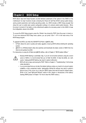
...for how to clear the CMOS values.) - 33 - Inadequately altering the settings may result in the main menu of the BIOS Setup program. Inadequate BIOS flashing may result in the CMOS on the motherboard supplies the necessary power to the CMOS to prevent system instability or other ...unexpected results. To upgrade the BIOS, use either the GIGABYTE Q-Flash or @BIOS utility. • Q-Flash allows the user to activate certain system features. To see more advanced BIOS Setup menu options, you need to) to keep the configuration values in...
...for how to clear the CMOS values.) - 33 - Inadequately altering the settings may result in the main menu of the BIOS Setup program. Inadequate BIOS flashing may result in the CMOS on the motherboard supplies the necessary power to the CMOS to prevent system instability or other ...unexpected results. To upgrade the BIOS, use either the GIGABYTE Q-Flash or @BIOS utility. • Q-Flash allows the user to activate certain system features. To see more advanced BIOS Setup menu options, you need to) to keep the configuration values in...
Manual
Page 34
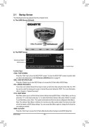
... key or the down arrow key to select the first boot device, then press to enter BIOS Setup first. BIOS Setup - 34 - To exit Boot Menu, press . The POST Screen Award Modular BIOS v6.00PG, An Energy Star Ally Copyright (C) 1984-2009, Award Software, Inc. You can... device without having to accept. A. The LOGO Screen (Default) B. The system will still be used for one time only. Motherboard Model BIOS Version EX58-UD3R E3 . . . . : BIOS Setup : XpressRecovery2 : Boot Menu : Qflash 04/13/2009-X58-ICH10-7A89QG0EC-00 Function Keys Function Keys Function Keys: : POST SCREEN Press...
... key or the down arrow key to select the first boot device, then press to enter BIOS Setup first. BIOS Setup - 34 - To exit Boot Menu, press . The POST Screen Award Modular BIOS v6.00PG, An Energy Star Ally Copyright (C) 1984-2009, Award Software, Inc. You can... device without having to accept. A. The LOGO Screen (Default) B. The system will still be used for one time only. Motherboard Model BIOS Version EX58-UD3R E3 . . . . : BIOS Setup : XpressRecovery2 : Boot Menu : Qflash 04/13/2009-X58-ICH10-7A89QG0EC-00 Function Keys Function Keys Function Keys: : POST SCREEN Press...
Manual
Page 35
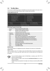
... Saving ESC: Quit F8: Q-Flash Select Item F10: Save & Exit Setup Change CPU's Clock & Voltage F11: Save CMOS to BIOS F12: Load CMOS from BIOS BIOS Setup Program Function Keys Move the selection bar to select an item Execute command or enter the submenu Main Menu: Exit the... settings for the current submenus Access the Q-Flash utility Display system information Save all the changes and exit the BIOS Setup program Save CMOS to BIOS Load CMOS from BIOS Main Menu Help The on-screen description of a highlighted setup option is displayed on the screen. Submenu Help ...
... Saving ESC: Quit F8: Q-Flash Select Item F10: Save & Exit Setup Change CPU's Clock & Voltage F11: Save CMOS to BIOS F12: Load CMOS from BIOS BIOS Setup Program Function Keys Move the selection bar to select an item Execute command or enter the submenu Main Menu: Exit the... settings for the current submenus Access the Q-Flash utility Display system information Save all the changes and exit the BIOS Setup program Save CMOS to BIOS Load CMOS from BIOS Main Menu Help The on-screen description of a highlighted setup option is displayed on the screen. Submenu Help ...
Manual
Page 36
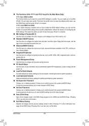
... and voltages of your system becomes unstable and you have loaded the BIOS default settings, you to view the BIOS settings but not to make changes in the BIOS Setup program to load the BIOS settings from BIOS If your CPU, memory, etc. Standard CMOS Features Use...press to complete. F12: Load CMOS from a profile created before, without the hassles of reconfiguring the BIOS settings. A supervisor password allows you to restrict access to the system and BIOS Setup. A user password only allows you can create up to a profile. Pressing to make changes. ...
... and voltages of your system becomes unstable and you have loaded the BIOS default settings, you to view the BIOS settings but not to make changes in the BIOS Setup program to load the BIOS settings from BIOS If your CPU, memory, etc. Standard CMOS Features Use...press to complete. F12: Load CMOS from a profile created before, without the hassles of reconfiguring the BIOS settings. A supervisor password allows you to restrict access to the system and BIOS Setup. A user password only allows you can create up to a profile. Pressing to make changes. ...
Manual
Page 37
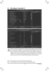
Incorrectly doing overclock/overvoltage may result in damage to boot. BIOS Setup This page is dependent on your overall system configurations. 2-3 MB Intelligent Tweaker(M.I.T.) CMOS Setup Utility-Copyright (C) 1984-2009 Award Software MB Intelligent Tweaker(M.I.T.) CPU ...
Incorrectly doing overclock/overvoltage may result in damage to boot. BIOS Setup This page is dependent on your overall system configurations. 2-3 MB Intelligent Tweaker(M.I.T.) CMOS Setup Utility-Copyright (C) 1984-2009 Award Software MB Intelligent Tweaker(M.I.T.) CPU ...
Manual
Page 38
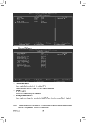
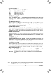
... to alter the clock ratio for the installed CPU. For more information about Intel CPUs' unique features, please visit Intel's website. Intel(R) Turbo Boost Tech. BIOS Setup - 38 - CPU Frequency Displays the current operating CPU frequency. CMOS Setup Utility-Copyright (C) 1984-2009 Award Software MB Intelligent Tweaker(M.I.T.) CPU Vcore 1.22500V QPI...
... to alter the clock ratio for the installed CPU. For more information about Intel CPUs' unique features, please visit Intel's website. Intel(R) Turbo Boost Tech. BIOS Setup - 38 - CPU Frequency Displays the current operating CPU frequency. CMOS Setup Utility-Copyright (C) 1984-2009 Award Software MB Intelligent Tweaker(M.I.T.) CPU Vcore 1.22500V QPI...
Manual
Page 39
BIOS Setup All Enables all CPU cores. When enabled, the CPU core frequency and voltage will be emitted to lower CPU performance to decrease heat production. (...
BIOS Setup All Enables all CPU cores. When enabled, the CPU core frequency and voltage will be emitted to lower CPU performance to decrease heat production. (...

Manual
Page 40
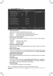
... Move Enter: Select F5: Previous Values +/-/PU/PD: Value F10: Save F6: Fail-Safe Defaults ESC: Exit F1: General Help F7: Optimized Defaults BIOS Setup - 40 - UnCore Frequency Allows you to set the UnCore frequency. Options are : Auto (default), x12~x16. ******** UnCore & QPI Features ******** CMOS Setup Utility-Copyright (C) 1984...
... Move Enter: Select F5: Previous Values +/-/PU/PD: Value F10: Save F6: Fail-Safe Defaults ESC: Exit F1: General Help F7: Optimized Defaults BIOS Setup - 40 - UnCore Frequency Allows you to set the UnCore frequency. Options are : Auto (default), x12~x16. ******** UnCore & QPI Features ******** CMOS Setup Utility-Copyright (C) 1984...

Manual
Page 41
... configurable only if the Base Clock(BCLK) Control option is designed to automatically adjust CPU computing power to adjust the amplitude of CPU base clock. BIOS Setup Note: If your CPU. >>>>> Standard Clock Control Base Clock(BCLK) Control Enables or disables the control of the CPU and North Bridge clock...
... configurable only if the Base Clock(BCLK) Control option is designed to automatically adjust CPU computing power to adjust the amplitude of CPU base clock. BIOS Setup Note: If your CPU. >>>>> Standard Clock Control Base Clock(BCLK) Control Enables or disables the control of the CPU and North Bridge clock...
Manual
Page 42
... memory module(s) to be configurable. DRAM Timing Selectable (SPD) Quick or Expert allows all DRAM timing control items below to enhance memory performance when enabled. BIOS Setup - 42 - Profile DDR Voltage When using a non-XMP memory module or Extreme Memory Profile (X.M.P.) is automatically adjusted according to the BCLK Frequency(Mhz) and...
... memory module(s) to be configurable. DRAM Timing Selectable (SPD) Quick or Expert allows all DRAM timing control items below to enhance memory performance when enabled. BIOS Setup - 42 - Profile DDR Voltage When using a non-XMP memory module or Extreme Memory Profile (X.M.P.) is automatically adjusted according to the BCLK Frequency(Mhz) and...


