Manual
Page 3
... For detailed product information, carefully read the User's Manual. „ For instructions on how to use GIGABYTE's unique features, read or download the information on/from the Support\Motherboard\Technology Guide page on your motherboard revision before updating motherboard... BIOS, drivers, or when looking for technical information. The logo is protected by GIGABYTE without GIGABYTE's prior written permission. Disclaimer Information in this manual are legally registered to the...
... For detailed product information, carefully read the User's Manual. „ For instructions on how to use GIGABYTE's unique features, read or download the information on/from the Support\Motherboard\Technology Guide page on your motherboard revision before updating motherboard... BIOS, drivers, or when looking for technical information. The logo is protected by GIGABYTE without GIGABYTE's prior written permission. Disclaimer Information in this manual are legally registered to the...
Manual
Page 4
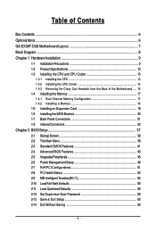
Table of Contents Box Contents ...6 OptionalItems ...6 GA-EX38T-DQ6 Motherboard Layout 7 Block Diagram ...8 Chapter 1 Hardware Installation 9 1-1 Installation Precautions 9 1-2 Product Specifications 10 1-3 Installing the CPU and CPU Cooler 13 ... Card 19 1-6 Installing the SATA Bracket 20 1-7 Back Panel Connectors 21 1-8 Internal Connectors 23 Chapter 2 BIOS Setup 37 2-1 Startup Screen 38 2-2 The Main Menu 39 2-3 Standard CMOS Features 41 2-4 Advanced BIOS Features 43 2-5 IntegratedPeripherals 45 2-6 Power Management Setup 49 2-7 PnP/PCI Configurations 51 2-8 PC Health Status...
Table of Contents Box Contents ...6 OptionalItems ...6 GA-EX38T-DQ6 Motherboard Layout 7 Block Diagram ...8 Chapter 1 Hardware Installation 9 1-1 Installation Precautions 9 1-2 Product Specifications 10 1-3 Installing the CPU and CPU Cooler 13 ... Card 19 1-6 Installing the SATA Bracket 20 1-7 Back Panel Connectors 21 1-8 Internal Connectors 23 Chapter 2 BIOS Setup 37 2-1 Startup Screen 38 2-2 The Main Menu 39 2-3 Standard CMOS Features 41 2-4 Advanced BIOS Features 43 2-5 IntegratedPeripherals 45 2-6 Power Management Setup 49 2-7 PnP/PCI Configurations 51 2-8 PC Health Status...
Manual
Page 5
...63 3-5 Contact Us ...63 Chapter 4 Unique Features 65 4-1 Xpress Recovery2 65 4-2 BIOS Update Utilities 70 4-2-1 Updating the BIOS with the Q-Flash Utility 70 4-2-2 Updating the BIOS with the @BIOS Utility 73 4-3 EasyTune 5 Pro 75 4-4 Dynamic Energy Saver 76 4-5 Windows Vista ...ReadyBoost 78 Chapter 5 Appendix ...79 5-1 Configuring SATA Hard Drive(s 79 5-1-1 Configuring Intel® ICH9R SATA Controllers 79 5-1-2 Configuring GIGABYTE...
...63 3-5 Contact Us ...63 Chapter 4 Unique Features 65 4-1 Xpress Recovery2 65 4-2 BIOS Update Utilities 70 4-2-1 Updating the BIOS with the Q-Flash Utility 70 4-2-2 Updating the BIOS with the @BIOS Utility 73 4-3 EasyTune 5 Pro 75 4-4 Dynamic Energy Saver 76 4-5 Windows Vista ...ReadyBoost 78 Chapter 5 Appendix ...79 5-1 Configuring SATA Hard Drive(s 79 5-1-1 Configuring Intel® ICH9R SATA Controllers 79 5-1-2 Configuring GIGABYTE...

Manual
Page 8
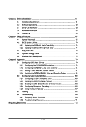
...) RJ45 RJ45 RTL RTL 8111B/ 8111B/ 8111C 8111C x1 x1 x1 x1 x1 PCI Express Bus 2 SATA 3Gb/s ATA-133/100/66/ 33 IDE Channel GIGABYTE SATA2 PCI Bus TSB43AB23 3 IEEE 1394a Host Interface Intel® X38 Intel® ICH9R CODEC DDR3 1900/1600/1333/ 1066/800 MHz Dual Channel Memory... MCH CLK (400/333/266/200 MHz) Dual BIOS 6 SATA 3Gb/s 12 USB Ports IT8718 Floppy LPT Port COM Port PS/2 KB/Mouse TPM 2 PCI PCI CLK (33 MHz) Surround Speaker Out Center/Subwoofer...
...) RJ45 RJ45 RTL RTL 8111B/ 8111B/ 8111C 8111C x1 x1 x1 x1 x1 PCI Express Bus 2 SATA 3Gb/s ATA-133/100/66/ 33 IDE Channel GIGABYTE SATA2 PCI Bus TSB43AB23 3 IEEE 1394a Host Interface Intel® X38 Intel® ICH9R CODEC DDR3 1900/1600/1333/ 1066/800 MHz Dual Channel Memory... MCH CLK (400/333/266/200 MHz) Dual BIOS 6 SATA 3Gb/s 12 USB Ports IT8718 Floppy LPT Port COM Port PS/2 KB/Mouse TPM 2 PCI PCI CLK (33 MHz) Surround Speaker Out Center/Subwoofer...
Manual
Page 12
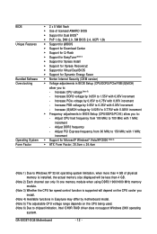
...with 0.025V increment Š Frequency adjustments in BIOS Setup (CPU/DDR3/PCI-E) allow you install. (Note 4) Available functions in BIOS Setup (CPU/DDR3/PCIe/FSB/(G)MCH) allow you to: - Increase (G)MCH voltage by 0.025V to 0.775V with 0.05V increment - GA-EX38T-DQ6 Motherboard - 12 - Increase DDR3 voltage by 0....for Q-Flash Š Support for EasyTune (Note 4) Š Support for Xpress Install Š Support for Xpress Recovery2 Š Support for Virtual Dual BIOS Š Support for Microsoft® Windows® Vista/XP/2000 (Note 6) Š ATX Form Factor; 30.5cm x 24.4cm (Note 1) ...
...with 0.025V increment Š Frequency adjustments in BIOS Setup (CPU/DDR3/PCI-E) allow you install. (Note 4) Available functions in BIOS Setup (CPU/DDR3/PCIe/FSB/(G)MCH) allow you to: - Increase (G)MCH voltage by 0.025V to 0.775V with 0.05V increment - GA-EX38T-DQ6 Motherboard - 12 - Increase DDR3 voltage by 0....for Q-Flash Š Support for EasyTune (Note 4) Š Support for Xpress Install Š Support for Xpress Recovery2 Š Support for Virtual Dual BIOS Š Support for Microsoft® Windows® Vista/XP/2000 (Note 6) Š ATX Form Factor; 30.5cm x 24.4cm (Note 1) ...
Manual
Page 17
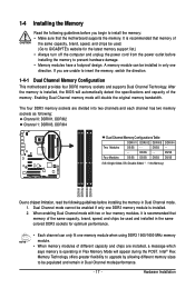
After the memory is installed, the BIOS will automatically detect the specifications and capacity of different capacity and chips are installed, a message which says memory is recommended that memory of the same ... sure that the motherboard supports the memory. DS/SS DS/SS (SS=Single-Sided, DS=Double-Sided, "- -"=No Memory) DDRIII1 DDRIII2 DDRIII3 DDRIII4 Due to GIGABYTE's website for optimum performance. • Each channel can only fit one direction. When enabling Dual Channel mode with two or four memory modules, it is...
After the memory is installed, the BIOS will automatically detect the specifications and capacity of different capacity and chips are installed, a message which says memory is recommended that memory of the same ... sure that the motherboard supports the memory. DS/SS DS/SS (SS=Single-Sided, DS=Double-Sided, "- -"=No Memory) DDRIII1 DDRIII2 DDRIII3 DDRIII4 Due to GIGABYTE's website for optimum performance. • Each channel can only fit one direction. When enabling Dual Channel mode with two or four memory modules, it is...
Manual
Page 19
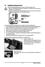
...Make sure the card is fully inserted into the slot. 4. Align the card with your expansion card in the slot. 3. If necessary, go to BIOS Setup to correctly install your expansion card. • Always turn off the computer and unplug the power cord from the power outlet before you begin... an expansion card to prevent hardware damage. PCI Express x16 Slot PCI Express x1 Slot PCI Slot Follow the steps below to make any required BIOS changes for your operating system. Example: Installing and Removing a PCI Express x16 Graphics Card: • Installing a Graphics Card: Gently push down ...
...Make sure the card is fully inserted into the slot. 4. Align the card with your expansion card in the slot. 3. If necessary, go to BIOS Setup to correctly install your expansion card. • Always turn off the computer and unplug the power cord from the power outlet before you begin... an expansion card to prevent hardware damage. PCI Express x16 Slot PCI Express x1 Slot PCI Slot Follow the steps below to make any required BIOS changes for your operating system. Example: Installing and Removing a PCI Express x16 Graphics Card: • Installing a Graphics Card: Gently push down ...
Manual
Page 28
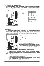
... replaced with an incorrect model. • Contact the place of purchase or local dealer if you are not able to keep the values (such as BIOS configurations, date, and time information) in S3/S4 sleep state or powered off (S5). System Status LED S0 On S1 Blinking S3/S4/S5 Off... system is operating. The LED is on the chassis to indicate system power status. The LED is off your computer and unplug the power cord. 2. GA-EX38T-DQ6 Motherboard - 28 -
... replaced with an incorrect model. • Contact the place of purchase or local dealer if you are not able to keep the values (such as BIOS configurations, date, and time information) in S3/S4 sleep state or powered off (S5). System Status LED S0 On S1 Blinking S3/S4/S5 Off... system is operating. The LED is on the chassis to indicate system power status. The LED is off your computer and unplug the power cord. 2. GA-EX38T-DQ6 Motherboard - 28 -
Manual
Page 29
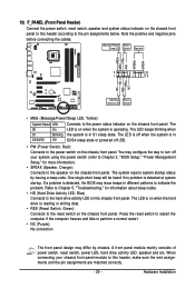
...chassis front panel. Note the positive and negative pins before connecting the cables. The S0 On LED is on when the system is detected, the BIOS may differ by issuing a beep code. RESRES+ NC Hard Drive Reset Activity LED Switch • MSG (Message/Power/Sleep LED, Yellow): System... panel. Message/Power/ Power Sleep LED Switch Speaker MSG+ MSG- When connecting your system using the power switch (refer to Chapter 2, "BIOS Setup," "Power Management Setup," for information about beep codes. • HD (Hard Drive Activity LED, Blue) Connects to the pin assignments below.
...chassis front panel. Note the positive and negative pins before connecting the cables. The S0 On LED is on when the system is detected, the BIOS may differ by issuing a beep code. RESRES+ NC Hard Drive Reset Activity LED Switch • MSG (Message/Power/Sleep LED, Yellow): System... panel. Message/Power/ Power Sleep LED Switch Speaker MSG+ MSG- When connecting your system using the power switch (refer to Chapter 2, "BIOS Setup," "Power Management Setup," for information about beep codes. • HD (Hard Drive Activity LED, Blue) Connects to the pin assignments below.

Manual
Page 34
...RSV1 SB3V SERIRQ GND CLKRUN LPCPD RSV2 23) CLR_CMOS (Clearing CMOS Jumper) Use this jumper to Chapter 2, "BIOS Setup," for a few seconds. 22) TPM (Trusted Platform Module Header) You may cause damage to the motherboard. •... Short: Clear CMOS Values • Always turn off your computer, be sure to factory defaults. date information and BIOS configurations) and reset the CMOS values to remove the jumper cap from the power outlet before clearing the CMOS values.... use a metal object like a screwdriver to touch the two pins for BIOS configurations). GA-EX38T-DQ6 Motherboard - 34 -
...RSV1 SB3V SERIRQ GND CLKRUN LPCPD RSV2 23) CLR_CMOS (Clearing CMOS Jumper) Use this jumper to Chapter 2, "BIOS Setup," for a few seconds. 22) TPM (Trusted Platform Module Header) You may cause damage to the motherboard. •... Short: Clear CMOS Values • Always turn off your computer, be sure to factory defaults. date information and BIOS configurations) and reset the CMOS values to remove the jumper cap from the power outlet before clearing the CMOS values.... use a metal object like a screwdriver to touch the two pins for BIOS configurations). GA-EX38T-DQ6 Motherboard - 34 -
Manual
Page 37
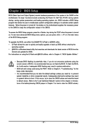
... key during the POST when the power is turned off, the battery on using the current version of BIOS, it with caution. To upgrade the BIOS, use either the GIGABYTE Q-Flash or @BIOS utility. • Q-Flash allows the user to clear the CMOS values.) - 37 - Inadequately altering the... settings may result in the CMOS on . Inadequate BIOS flashing may result in system's failure to keep the configuration ...
... key during the POST when the power is turned off, the battery on using the current version of BIOS, it with caution. To upgrade the BIOS, use either the GIGABYTE Q-Flash or @BIOS utility. • Q-Flash allows the user to clear the CMOS values.) - 37 - Inadequately altering the... settings may result in the CMOS on . Inadequate BIOS flashing may result in system's failure to keep the configuration ...
Manual
Page 38
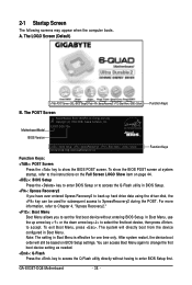
...GA-EX38T-DQ6 Motherboard - 38 - EX38T-DQ6 F3b . . . . : BIOS Setup : XpressRecovery2 : Boot Menu : Qflash 02/04/2008-X38-ICH9-6A89OG0FC-00 Function Keys Function Keys: : POST Screen Press the key to show the BIOS POST screen at system startup, refer to the instructions on the Full Screen LOGO Show item on BIOS...select the first boot device, then press to XpressRecovery2 during the POST. You can be based on page 44. : BIOS Setup Press the key to enter BIOS Setup or to access the Q-Flash utility in Boot Menu. 2-1 Startup Screen The following screens may appear when the computer...
...GA-EX38T-DQ6 Motherboard - 38 - EX38T-DQ6 F3b . . . . : BIOS Setup : XpressRecovery2 : Boot Menu : Qflash 02/04/2008-X38-ICH9-6A89OG0FC-00 Function Keys Function Keys: : POST Screen Press the key to show the BIOS POST screen at system startup, refer to the instructions on the Full Screen LOGO Show item on BIOS...select the first boot device, then press to XpressRecovery2 during the POST. You can be based on page 44. : BIOS Setup Press the key to enter BIOS Setup or to access the Q-Flash utility in Boot Menu. 2-1 Startup Screen The following screens may appear when the computer...
Manual
Page 39
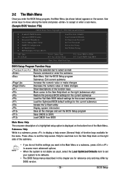
...the current submenus Access the Q-Flash utility Display system information Save all the changes and exit the BIOS Setup program Save CMOS to the Item Help block on the screen. BIOS Setup BIOS Setup Program Function Keys Move the selection bar to select an item Execute command or enter the ...Save & Exit Setup Exit Without Saving ESC: Quit F8: Q-Flash KLJI: Select Item F10: Save & Exit Setup F11: Save CMOS to BIOS F12: Load CMOS from BIOS Main Menu Help The onscreen description of a highlighted setup option is in the Item Help block on the right side of the function...
...the current submenus Access the Q-Flash utility Display system information Save all the changes and exit the BIOS Setup program Save CMOS to the Item Help block on the screen. BIOS Setup BIOS Setup Program Function Keys Move the selection bar to select an item Execute command or enter the ...Save & Exit Setup Exit Without Saving ESC: Quit F8: Q-Flash KLJI: Select Item F10: Save & Exit Setup F11: Save CMOS to BIOS F12: Load CMOS from BIOS Main Menu Help The onscreen description of a highlighted setup option is in the Item Help block on the right side of the function...
Manual
Page 40
... this menu to configure the clock, frequency and voltages of your system becomes unstable and you have loaded the BIOS default settings, you can also carry out this task.) GA-EX38T-DQ6 Motherboard - 40 - First enter the profile name (to erase the default profile name, use this menu to... complete. ` F12 : Load CMOS from a profile created before, without the hassles of reconfiguring the BIOS settings. It allows you to restrict access...
... this menu to configure the clock, frequency and voltages of your system becomes unstable and you have loaded the BIOS default settings, you can also carry out this task.) GA-EX38T-DQ6 Motherboard - 40 - First enter the profile name (to erase the default profile name, use this menu to... complete. ` F12 : Load CMOS from a profile created before, without the hassles of reconfiguring the BIOS settings. It allows you to restrict access...

Manual
Page 41
... F5: Previous Values +/-/PU/PD: Value F10: Save F6: Fail-Safe Defaults ESC: Exit F1: General Help F7: Optimized Defaults Date Sets the system date. BIOS Setup
... F5: Previous Values +/-/PU/PD: Value F10: Save F6: Fail-Safe Defaults ESC: Exit F1: General Help F7: Optimized Defaults Date Sets the system date. BIOS Setup
Manual
Page 42
... The total amount of heads. Sets the hard drive access mode. The following fields display your IDE/SATA devices by the BIOS POST. Capacity Approximate capacity of cylinders. Cylinder Head Precomp Landing Zone Number of the currently installed hard drive. Halt on the... all other errors. Options are : None, 360K/5.25", 1.2M/5.25", 720K/3.5", 1.44M/3.5", 2.88M/3.5". GA-EX38T-DQ6 Motherboard - 42 - • Auto • None • Manual Access Mode Lets BIOS automatically detect IDE/SATA devices during the POST. (Default) If no IDE/SATA devices are used , set...
... The total amount of heads. Sets the hard drive access mode. The following fields display your IDE/SATA devices by the BIOS POST. Capacity Approximate capacity of cylinders. Cylinder Head Precomp Landing Zone Number of the currently installed hard drive. Halt on the... all other errors. Options are : None, 360K/5.25", 1.2M/5.25", 720K/3.5", 1.44M/3.5", 2.88M/3.5". GA-EX38T-DQ6 Motherboard - 42 - • Auto • None • Manual Access Mode Lets BIOS automatically detect IDE/SATA devices during the POST. (Default) If no IDE/SATA devices are used , set...
Manual
Page 43
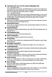
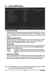
... key to select a device and press to move it up or down on the list. Setup A password is only required for entering the BIOS Setup program. HDD S.M.A.R.T. Use the up or down arrow key to select a hard drive, then press the plus key (or ) or ... this feature. For more information about Intel CPUs' unique features, please visit Intel's website. - 43 - 2-4 Advanced BIOS Features CMOS Setup Utility-Copyright (C) 1984-2008 Award Software Advanced BIOS Features ` Hard Disk Boot Priority First Boot Device [Press Enter] [Floppy] Item Help Menu Level` Second Boot Device ...
... key to select a device and press to move it up or down on the list. Setup A password is only required for entering the BIOS Setup program. HDD S.M.A.R.T. Use the up or down arrow key to select a hard drive, then press the plus key (or ) or ... this feature. For more information about Intel CPUs' unique features, please visit Intel's website. - 43 - 2-4 Advanced BIOS Features CMOS Setup Utility-Copyright (C) 1984-2008 Award Software Advanced BIOS Features ` Hard Disk Boot Priority First Boot Device [Press Enter] [Floppy] Item Help Menu Level` Second Boot Device ...
Manual
Page 45
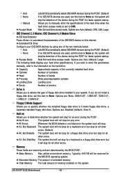
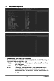
BIOS Setup Advanced Host Controller Interface (AHCI) is an interface specification that allows the storage driver to PATA mode. (Default) RAID Enables RAID for the SATA ...
BIOS Setup Advanced Host Controller Interface (AHCI) is an interface specification that allows the storage driver to PATA mode. (Default) RAID Enables RAID for the SATA ...
Manual
Page 47
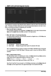
... or a 10/100 Mbps hub, the following information for diagnosing your LAN cable: When No LAN Cable Is Attached... When LAN Cable Is Functioning Normally... BIOS Setup If no LAN cable is attached to the following message will only operate at Port..... Note: The Gigabit hub will appear: Start detecting at...
... or a 10/100 Mbps hub, the following information for diagnosing your LAN cable: When No LAN Cable Is Attached... When LAN Cable Is Functioning Normally... BIOS Setup If no LAN cable is attached to the following message will only operate at Port..... Note: The Gigabit hub will appear: Start detecting at...
Manual
Page 49
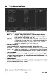
... power button and then the system will enter suspend mode. Note: To use this function, you need an ATX power supply providing at any time. BIOS Setup Soft-Off by Alarm x Date (of Month) Alarm x Time (hh:mm:ss) Alarm HPET Support (Note) HPET Mode (Note) Power On By Mouse Power...
... power button and then the system will enter suspend mode. Note: To use this function, you need an ATX power supply providing at any time. BIOS Setup Soft-Off by Alarm x Date (of Month) Alarm x Time (hh:mm:ss) Alarm HPET Support (Note) HPET Mode (Note) Power On By Mouse Power...


