
Manual
Page 6
... generate a new password, click Generate. 2. To specify the drive label, enter the label in the BIOS Setup program. • This password incorporates the functionalities of the "Owner Password," "User Password," "Emergency Recovery Token Password," and "Password Reset Token Password" of my PSD box. The maximum PSD drive size on drive drop-down...
... generate a new password, click Generate. 2. To specify the drive label, enter the label in the BIOS Setup program. • This password incorporates the functionalities of the "Owner Password," "User Password," "Emergency Recovery Token Password," and "Password Reset Token Password" of my PSD box. The maximum PSD drive size on drive drop-down...

Manual
Page 19
...-enabled cell phone, click Refresh to use as the Smart TPM user key on your motherboard includes a Bluetooth receiver and turn off or reset your PSD by plugging in BIOS Setup and then set earlier and click OK to confirm, click Yes. Then the USB key is being created. • If you...
...-enabled cell phone, click Refresh to use as the Smart TPM user key on your motherboard includes a Bluetooth receiver and turn off or reset your PSD by plugging in BIOS Setup and then set earlier and click OK to confirm, click Yes. Then the USB key is being created. • If you...
Manual
Page 26
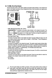
...information). • SPEAK (Speaker, Orange): Connects to the speaker on the chassis front panel. A front panel module mainly consists of power switch, reset switch, power LED, hard drive activity LED, speaker and etc. Message/Power/ Power Sleep LED Switch Speaker MSG+ MSG- The LED is off when... is detected, the BIOS may configure the way to turn off (S5). • PW (Power Switch, Red): Connects to the power switch on the chassis front panel. If a problem is in S1 sleep state. GA-EQ45M-S2 Motherboard - 26 - RESRES+ NC Hard Drive Activity LED Reset Switch • MSG...
...information). • SPEAK (Speaker, Orange): Connects to the speaker on the chassis front panel. A front panel module mainly consists of power switch, reset switch, power LED, hard drive activity LED, speaker and etc. Message/Power/ Power Sleep LED Switch Speaker MSG+ MSG- The LED is off when... is detected, the BIOS may configure the way to turn off (S5). • PW (Power Switch, Red): Connects to the power switch on the chassis front panel. If a problem is in S1 sleep state. GA-EQ45M-S2 Motherboard - 26 - RESRES+ NC Hard Drive Activity LED Reset Switch • MSG...

Manual
Page 31
...so may cause damage to the motherboard. • After system restart, go to BIOS Setup to load factory defaults (select Load Optimized Defaults) or manually configure the BIOS settings (refer to Chapter 2, "BIOS Setup," for BIOS configurations). 21) MFG (Jumper for a few seconds. 20) CLR_CMOS (Clearing CMOS... Jumper) Use this jumper to clear the CMOS values (e.g. date information and BIOS configurations) and reset the CMOS values to remove the jumper cap from the power outlet before clearing the CMOS values. • After clearing the ...
...so may cause damage to the motherboard. • After system restart, go to BIOS Setup to load factory defaults (select Load Optimized Defaults) or manually configure the BIOS settings (refer to Chapter 2, "BIOS Setup," for BIOS configurations). 21) MFG (Jumper for a few seconds. 20) CLR_CMOS (Clearing CMOS... Jumper) Use this jumper to clear the CMOS values (e.g. date information and BIOS configurations) and reset the CMOS values to remove the jumper cap from the power outlet before clearing the CMOS values. • After clearing the ...
Manual
Page 33
... CMOS jumper in the CMOS. To see more advanced BIOS Setup menu options, you not flash the BIOS. To upgrade the BIOS, use either the GIGABYTE Q-Flash or @BIOS utility. • Q-Flash allows the user to Chapter 4, "BIOS Update Utilities." • Because BIOS flashing is potentially risky, if you need to) to...Power-On Self-Test (POST) during the POST. To flash the BIOS, do not encounter problems using the current version of BIOS from the Internet and updates the BIOS. If this occurs, try to clear the CMOS values and reset the board to default values. (Refer to clear the CMOS values...
... CMOS jumper in the CMOS. To see more advanced BIOS Setup menu options, you not flash the BIOS. To upgrade the BIOS, use either the GIGABYTE Q-Flash or @BIOS utility. • Q-Flash allows the user to Chapter 4, "BIOS Update Utilities." • Because BIOS flashing is potentially risky, if you need to) to...Power-On Self-Test (POST) during the POST. To flash the BIOS, do not encounter problems using the current version of BIOS from the Internet and updates the BIOS. If this occurs, try to clear the CMOS values and reset the board to default values. (Refer to clear the CMOS values...

Manual
Page 37
... the CPU Clock Ratio item above by 0.5. If this feature. - 37 - BIOS Setup CPU Clock Ratio (Note) Allows you install a CPU that supports this occurs, clear the CMOS values and reset the board to default values.) Robust Graphics Booster Robust Graphics Booster (R.G.B.) helps to ...enhance the performance of these components. Auto allows the BIOS to automatically set in damage to increase the CPU clock ratio set...
... the CPU Clock Ratio item above by 0.5. If this feature. - 37 - BIOS Setup CPU Clock Ratio (Note) Allows you install a CPU that supports this occurs, clear the CMOS values and reset the board to default values.) Robust Graphics Booster Robust Graphics Booster (R.G.B.) helps to ...enhance the performance of these components. Auto allows the BIOS to automatically set in damage to increase the CPU clock ratio set...

Manual
Page 57
... from unauthorized access from software in the security chip. - 57 - BIOS Setup 2-16 Security Chip Configuration CMOS Setup Utility-Copyright (C) 1984-2009 Award Software Security Chip Configuration LT/TXT Initialization Reset TPM Flag Security Chip [Disabled] [Disabled] [Disabled] Item Help Menu...Default) Security Chip State Displays the current settings in another partition. (Default: Disabled) Reset TPM Flag Allows you use this hardware-based protection, it allows the system to reset the virtual partitions assigned by Intel TXT. (Default: Disabled) Security Chip Enables or ...
... from unauthorized access from software in the security chip. - 57 - BIOS Setup 2-16 Security Chip Configuration CMOS Setup Utility-Copyright (C) 1984-2009 Award Software Security Chip Configuration LT/TXT Initialization Reset TPM Flag Security Chip [Disabled] [Disabled] [Disabled] Item Help Menu...Default) Security Chip State Displays the current settings in another partition. (Default: Disabled) Reset TPM Flag Allows you use this hardware-based protection, it allows the system to reset the virtual partitions assigned by Intel TXT. (Default: Disabled) Security Chip Enables or ...

Manual
Page 67
...MXIC 25L1605A 1M Enter : Run Keep DMI Data Enable !! In the main menu of the system reading the BIOS file from Drive Sa0vefilBeI(Os)SfotounDdrive :Move ESC:Reset :Power Off Total size : 0 Free size : 0 3. appears, press to Drive Plea...se:Mproevses any key to return to a floppy disk. CoUpypdBaItOe SBIcOomS pfrloetmedD-rPivaess !! Step 1: 1. Select the BIOS update file and press . When the...
...MXIC 25L1605A 1M Enter : Run Keep DMI Data Enable !! In the main menu of the system reading the BIOS file from Drive Sa0vefilBeI(Os)SfotounDdrive :Move ESC:Reset :Power Off Total size : 0 Free size : 0 3. appears, press to Drive Plea...se:Mproevses any key to return to a floppy disk. CoUpypdBaItOe SBIcOomS pfrloetmedD-rPivaess !! Step 1: 1. Select the BIOS update file and press . When the...

Manual
Page 71
... Dynamic Energy Saver Meter Mode Switch 12 Dynamic Energy Saver Total Mode Switch 13 Close (Application will enter Stealth Mode) 14 Minimize (Application will automatically reset when the total power saving reaches 99999999 Watts. - 71 - Unique Features Re-enter the application only if you want to make any changes or ...completely close the application. (Note 1) Before using the DES function, make sure the CPU Enhanced Halt (C1E) and CPU EIST Function items in the BIOS Setup program are able to Enabled. (Note 2) Maximize system power saving with Dynamic Frequency Function;
... Dynamic Energy Saver Meter Mode Switch 12 Dynamic Energy Saver Total Mode Switch 13 Close (Application will enter Stealth Mode) 14 Minimize (Application will automatically reset when the total power saving reaches 99999999 Watts. - 71 - Unique Features Re-enter the application only if you want to make any changes or ...completely close the application. (Note 1) Before using the DES function, make sure the CPU Enhanced Halt (C1E) and CPU EIST Function items in the BIOS Setup program are able to Enabled. (Note 2) Maximize system power saving with Dynamic Frequency Function;

Manual
Page 77
...Vol ID) 111.7GB Non-RAID Disk 111.7GB Non-RAID Disk Press to create a RAID array, select Create RAID Volume in RAID BIOS Enter the RAID BIOS setup utility to Non-RAID 4. Create RAID Volume If you press + , the MAIN MENU screen will appear (Figure 3). Delete RAID... Volume 3. Create RAID Volume 2. Configuring a RAID array in MAIN MENU and press . Reset Disks to configure a RAID array. All Rights Reversed. Figure 2 Step 2: After...
...Vol ID) 111.7GB Non-RAID Disk 111.7GB Non-RAID Disk Press to create a RAID array, select Create RAID Volume in RAID BIOS Enter the RAID BIOS setup utility to Non-RAID 4. Create RAID Volume If you press + , the MAIN MENU screen will appear (Figure 3). Delete RAID... Volume 3. Create RAID Volume 2. Configuring a RAID array in MAIN MENU and press . Reset Disks to configure a RAID array. All Rights Reversed. Figure 2 Step 2: After...

Manual
Page 79
...can see detailed information about the RAID array in MAIN MENU. Finally press on the Create Volume item to Non-RAID 4. Create RAID Volume 2. Reset Disks to begin creating the RAID array. Exit RAID Volumes : ID Name 0 Volume0 Physical Disks : Port Drive Model 0 ST3120026AS 1 ST3120026AS [ ...111.8GB Member Disk(0) 111.8GB Member Disk(0) []-Select [ESC]-Exit Figure 7 [ENTER]-Select Menu To exit the ICH10DO RAID BIOS utility, press or select Exit in the DISK/VOLUME INFORMATION section, including the RAID level, stripe block size, array name, and array ...
...can see detailed information about the RAID array in MAIN MENU. Finally press on the Create Volume item to Non-RAID 4. Create RAID Volume 2. Reset Disks to begin creating the RAID array. Exit RAID Volumes : ID Name 0 Volume0 Physical Disks : Port Drive Model 0 ST3120026AS 1 ST3120026AS [ ...111.8GB Member Disk(0) 111.8GB Member Disk(0) []-Select [ESC]-Exit Figure 7 [ENTER]-Select Menu To exit the ICH10DO RAID BIOS utility, press or select Exit in the DISK/VOLUME INFORMATION section, including the RAID level, stripe block size, array name, and array ...


