Manual
Page 1
GA-EP45T-UD3LR LGA775 socket motherboard for Intel® Core TM processor family/ Intel® Pentium® processor family/Intel® Celeron® processor family User's Manual Rev. 1101 12ME-EP45TU3LR-1101R
GA-EP45T-UD3LR LGA775 socket motherboard for Intel® Core TM processor family/ Intel® Pentium® processor family/Intel® Celeron® processor family User's Manual Rev. 1101 12ME-EP45TU3LR-1101R
Manual
Page 2
Motherboard GA-EP45T-UD3LR Oct. 24, 2008 Motherboard GA-EP45T-UD3LR Oct. 24, 2008
Motherboard GA-EP45T-UD3LR Oct. 24, 2008 Motherboard GA-EP45T-UD3LR Oct. 24, 2008
Manual
Page 3
...Copyright © 2008 GIGA-BYTE TECHNOLOGY CO., LTD. No part of GIGABYTE. Example: For product-related information, check on our website at: http://www.gigabyte.com.tw Identifying Your Motherboard Revision The revision number on how to the specifications and features in this...Classifications In order to assist in the use GIGABYTE's unique features, read the User's Manual. For instructions on your motherboard revision before updating motherboard BIOS, drivers, or when looking for technical information. Check your motherboard looks like this manual may be made by...
...Copyright © 2008 GIGA-BYTE TECHNOLOGY CO., LTD. No part of GIGABYTE. Example: For product-related information, check on our website at: http://www.gigabyte.com.tw Identifying Your Motherboard Revision The revision number on how to the specifications and features in this...Classifications In order to assist in the use GIGABYTE's unique features, read the User's Manual. For instructions on your motherboard revision before updating motherboard BIOS, drivers, or when looking for technical information. Check your motherboard looks like this manual may be made by...
Manual
Page 4
Table of Contents Box Contents ...6 OptionalItems...6 GA-EP45T-UD3LR Motherboard Layout 7 Block Diagram...8 Chapter 1 Hardware Installation 9 1-1 Installation Precautions 9 1-2 Product Specifications 10 1-3 Installing the CPU and CPU Cooler 13 1-3-1 Installing the CPU 13 1-3-2 Installing the CPU ...
Table of Contents Box Contents ...6 OptionalItems...6 GA-EP45T-UD3LR Motherboard Layout 7 Block Diagram...8 Chapter 1 Hardware Installation 9 1-1 Installation Precautions 9 1-2 Product Specifications 10 1-3 Installing the CPU and CPU Cooler 13 1-3-1 Installing the CPU 13 1-3-2 Installing the CPU ...
Manual
Page 6
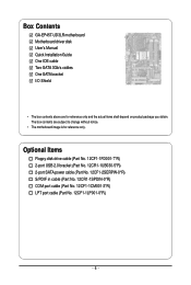
.... 12CF1-2SERPW-0*R) S/PDIF in cable (Part No. 12CR1-1SPDIN-0*R) COM port cable (Part No. 12CF1-1CM001-3*R) LPT port cable (Part No. 12CF1-1LP001-0*R) - 6 - Box Contents GA-EP45T-UD3LR motherboard Motherboard driver disk User's Manual Quick Installation Guide One IDE cable Two SATA 3Gb/s cables One SATA bracket I/O Shield • The box contents above are subject...
.... 12CF1-2SERPW-0*R) S/PDIF in cable (Part No. 12CR1-1SPDIN-0*R) COM port cable (Part No. 12CF1-1CM001-3*R) LPT port cable (Part No. 12CF1-1LP001-0*R) - 6 - Box Contents GA-EP45T-UD3LR motherboard Motherboard driver disk User's Manual Quick Installation Guide One IDE cable Two SATA 3Gb/s cables One SATA bracket I/O Shield • The box contents above are subject...

Manual
Page 7
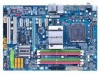
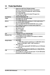
GA-EP45T-UD3LR Motherboard Layout KB_MS R_SPDIF R_USB_1 R_USB_2 R_USB_3 USB_LAN ATX_12V PHASE LED CPU_FAN PWR_FAN ATX LGA775 DDR3_1 GA-EP45T-UD3LR DDR3_2 DDR3_3 DDR3_4 FDD SYS_FAN2 F_AUDIO SYS_FAN1 AUDIO Intel® P45 RTL8111C PCIEX1_1 PCIEX1_2 PCIEX16 CODEC SPDIF_O SPDIF_I PCIEX1_3 PCIEX1_4 B_BIOS M_BIOS BAT PCI1 CLR_CMOS IT8718 PCI2 CD_IN CI Intel® ICH10R SATA2_3 SATA2_0 SATA2_4 SATA2_ 1 JMicron 368 IDE SATA2_5 SATA2_2 F_USB1 F_PANEL PWR_LED COMA LPT F_USB2 - 7 -
GA-EP45T-UD3LR Motherboard Layout KB_MS R_SPDIF R_USB_1 R_USB_2 R_USB_3 USB_LAN ATX_12V PHASE LED CPU_FAN PWR_FAN ATX LGA775 DDR3_1 GA-EP45T-UD3LR DDR3_2 DDR3_3 DDR3_4 FDD SYS_FAN2 F_AUDIO SYS_FAN1 AUDIO Intel® P45 RTL8111C PCIEX1_1 PCIEX1_2 PCIEX16 CODEC SPDIF_O SPDIF_I PCIEX1_3 PCIEX1_4 B_BIOS M_BIOS BAT PCI1 CLR_CMOS IT8718 PCI2 CD_IN CI Intel® ICH10R SATA2_3 SATA2_0 SATA2_4 SATA2_ 1 JMicron 368 IDE SATA2_5 SATA2_2 F_USB1 F_PANEL PWR_LED COMA LPT F_USB2 - 7 -

Manual
Page 9
... using the product, please verify that all cables and power connectors of your hardware components are connected. • To prevent damage to the motherboard, do not allow screws to come in a high-temperature environment. • Turning on the power, make sure they are connected tightly and... securely. • When handling the motherboard, avoid touching any metal leads or connectors. • It is best to wear an electrostatic discharge (ESD) wrist strap when handling electronic...
... using the product, please verify that all cables and power connectors of your hardware components are connected. • To prevent damage to the motherboard, do not allow screws to come in a high-temperature environment. • Turning on the power, make sure they are connected tightly and... securely. • When handling the motherboard, avoid touching any metal leads or connectors. • It is best to wear an electrostatic discharge (ESD) wrist strap when handling electronic...
Manual
Page 10
... system memory (Note 1) Dual channel memory architecture Support for DDR3 2200/1600/1333/1066/800 MHz memory modules (Go to GIGABYTE's website for the latest memory support list.) Realtek ALC888 codec High Definition Audio 2/4/5.1/7.1-channel Support for S/...100/66/33 and up to 2 IDE devices iTE IT8718 chip: - 1 x floppy disk drive connector supporting up to the internal USB headers) GA-EP45T-UD3LR Motherboard - 10 - Support for CD In 1 x Realtek 8111C chip (10/100/1000 Mbit) 1 x PCI Express x16 slot, running ...
... system memory (Note 1) Dual channel memory architecture Support for DDR3 2200/1600/1333/1066/800 MHz memory modules (Go to GIGABYTE's website for the latest memory support list.) Realtek ALC888 codec High Definition Audio 2/4/5.1/7.1-channel Support for S/...100/66/33 and up to 2 IDE devices iTE IT8718 chip: - 1 x floppy disk drive connector supporting up to the internal USB headers) GA-EP45T-UD3LR Motherboard - 10 - Support for CD In 1 x Realtek 8111C chip (10/100/1000 Mbit) 1 x PCI Express x16 slot, running ...
Manual
Page 12
GA-EP45T-UD3LR Motherboard - 12 - BIOS Unique Features Bundled Software Operating System Form Factor 2 x 8 Mbit flash Use of licensed AWARD BIOS Support for DualBIOSTM PnP 1.... CPU/System fan speed control function is supported will depend on the CPU/ System cooler you install. (Note 3) Available functions in EasyTune may differ by motherboard model.
GA-EP45T-UD3LR Motherboard - 12 - BIOS Unique Features Bundled Software Operating System Form Factor 2 x 8 Mbit flash Use of licensed AWARD BIOS Support for DualBIOSTM PnP 1.... CPU/System fan speed control function is supported will depend on the CPU/ System cooler you install. (Note 3) Available functions in EasyTune may differ by motherboard model.
Manual
Page 13
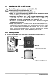
mended that the motherboard supports the CPU. (Go to GIGABYTE's website for the peripherals. Hardware Installation Locate the alignment keys on the motherboard CPU socket and the notches on the CPU. LGA775 CPU Socket Alignment Key LGA 775 CPU Alignment Key Pin One Corner of the CPU. • ...
mended that the motherboard supports the CPU. (Go to GIGABYTE's website for the peripherals. Hardware Installation Locate the alignment keys on the motherboard CPU socket and the notches on the CPU. LGA775 CPU Socket Alignment Key LGA 775 CPU Alignment Key Pin One Corner of the CPU. • ...
Manual
Page 14
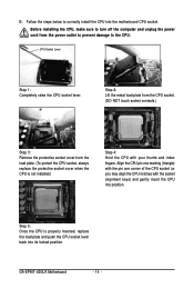
GA-EP45T-UD3LR Motherboard - 14 - CPU Socket Lever Step 1: Completely raise the CPU socket lever. Step 2: Lift the metal load plate from the CPU socket. (DO NOT touch socket contacts.) Step 3: Remove the protective socket cover from the power outlet to prevent damage to correctly install the CPU into the motherboard CPU socket. Before installing the...
GA-EP45T-UD3LR Motherboard - 14 - CPU Socket Lever Step 1: Completely raise the CPU socket lever. Step 2: Lift the metal load plate from the CPU socket. (DO NOT touch socket contacts.) Step 3: Remove the protective socket cover from the power outlet to prevent damage to correctly install the CPU into the motherboard CPU socket. Before installing the...
Manual
Page 15
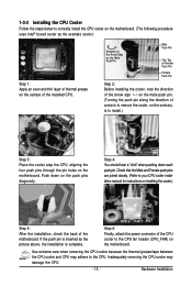
... grease on the surface of the installed CPU. Push down each push pin. Step 6: Finally, attach the power connector of the motherboard. Check that the Male and Female push pins are joined closely. (Refer to your CPU cooler installation manual for instructions on the... motherboard. Hardware Installation 1-3-2 Installing the CPU Cooler Follow the steps below to correctly install the CPU cooler on the motherboard. (The following procedure uses Intel® boxed cooler as the picture above, the ...
... grease on the surface of the installed CPU. Push down each push pin. Step 6: Finally, attach the power connector of the motherboard. Check that the Male and Female push pins are joined closely. (Refer to your CPU cooler installation manual for instructions on the... motherboard. Hardware Installation 1-3-2 Installing the CPU Cooler Follow the steps below to correctly install the CPU cooler on the motherboard. (The following procedure uses Intel® boxed cooler as the picture above, the ...
Manual
Page 16
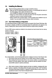
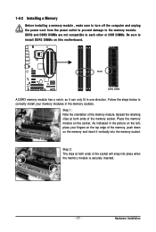
.../performance. The four DDR3 memory sockets are installed, a message which says memory is operating in Flex Memory Mode will appear during the POST. GA-EP45T-UD3LR Motherboard - 16 - DS/SS - - - - When enabling Dual Channel mode with two or four memory modules, it is installed, the BIOS... Channel mode. 1. It is installed. 2. When memory modules of the same capacity, brand, speed, and chips be used . (Go to GIGABYTE's website for optimum performance. 1-4 Installing the Memory Read the following guidelines before you are unable to chipset limitation, read the following : Channel 0:...
.../performance. The four DDR3 memory sockets are installed, a message which says memory is operating in Flex Memory Mode will appear during the POST. GA-EP45T-UD3LR Motherboard - 16 - DS/SS - - - - When enabling Dual Channel mode with two or four memory modules, it is installed, the BIOS... Channel mode. 1. It is installed. 2. When memory modules of the same capacity, brand, speed, and chips be used . (Go to GIGABYTE's website for optimum performance. 1-4 Installing the Memory Read the following guidelines before you are unable to chipset limitation, read the following : Channel 0:...
Manual
Page 17
... the memory sockets. Spread the retaining clips at both ends of the socket will snap into the memory socket. Place the memory module on this motherboard. As indicated in the picture on the left, place your memory modules in one direction.
... the memory sockets. Spread the retaining clips at both ends of the socket will snap into the memory socket. Place the memory module on this motherboard. As indicated in the picture on the left, place your memory modules in one direction.
Manual
Page 18
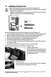
... Read the following guidelines before installing an expansion card to release the card and then pull the card straight up from the chassis back panel. 2. GA-EP45T-UD3LR Motherboard - 18 - If necessary, go to BIOS Setup to the chassis back panel with the expansion card in the slot. 3. PCI Express x1 Slot PCI Express...
... Read the following guidelines before installing an expansion card to release the card and then pull the card straight up from the chassis back panel. 2. GA-EP45T-UD3LR Motherboard - 18 - If necessary, go to BIOS Setup to the chassis back panel with the expansion card in the slot. 3. PCI Express x1 Slot PCI Express...

Manual
Page 19
... to install the SATA bracket: Step 1: Locate one end of the cable from the bracket to the SATA port on the bracket. nector on your motherboard. Before connecting the SATA signal cable, make sure to turn off your SATA device. the external SATA con- Hardware Installation Step 2: Connect the SATA cable...
... to install the SATA bracket: Step 1: Locate one end of the cable from the bracket to the SATA port on the bracket. nector on your motherboard. Before connecting the SATA signal cable, make sure to turn off your SATA device. the external SATA con- Hardware Installation Step 2: Connect the SATA cable...
Manual
Page 20
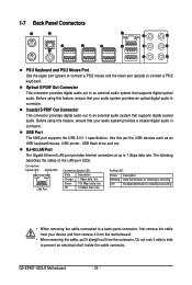
Do not rock it straight out from the connector. GA-EP45T-UD3LR Motherboard - 20 - Before using this port for USB devices such as an USB keyboard/mouse, USB printer, USB flash drive and etc. The following describes the ... rate. Optical S/PDIF Out Connector This connector provides digital audio out to an external audio system that your device and then remove it from the motherboard. • When removing the cable, pull it side to side to connect a PS/2 keyboard. RJ-45 LAN Port The Gigabit Ethernet LAN port provides Internet...
Do not rock it straight out from the connector. GA-EP45T-UD3LR Motherboard - 20 - Before using this port for USB devices such as an USB keyboard/mouse, USB printer, USB flash drive and etc. The following describes the ... rate. Optical S/PDIF Out Connector This connector provides digital audio out to an external audio system that your device and then remove it from the motherboard. • When removing the cable, pull it side to side to connect a PS/2 keyboard. RJ-45 LAN Port The Gigabit Ethernet LAN port provides Internet...

Manual
Page 22
... sure to the connector on the motherboard. Unplug the power cord from the power outlet to prevent damage to the devices. • After installing the device and before connecting external devices: • First make sure the device cable has been securely attached to turn off the devices and your computer. GA-EP45T-UD3LR Motherboard - 22 -
... sure to the connector on the motherboard. Unplug the power cord from the power outlet to prevent damage to the devices. • After installing the device and before connecting external devices: • First make sure the device cable has been securely attached to turn off the devices and your computer. GA-EP45T-UD3LR Motherboard - 22 -
Manual
Page 23
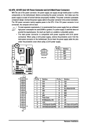
... power supply cable into pins under the protective cover when using a 2x12 power supply, remove the protective cover from the main power connector on the motherboard. The 12V power connector mainly supplies power to the power connector in the correct orientation. If a power supply is used (500W or greater). When using... all devices are properly installed. Before connecting the power connector, first make sure the power supply is turned off and all the components on the motherboard.
... power supply cable into pins under the protective cover when using a 2x12 power supply, remove the protective cover from the main power connector on the motherboard. The 12V power connector mainly supplies power to the power connector in the correct orientation. If a power supply is used (500W or greater). When using... all devices are properly installed. Before connecting the power connector, first make sure the power supply is turned off and all the components on the motherboard.
Manual
Page 24
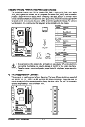
...No. 1 Definition GND 1 SYS_FAN2 2 Speed Control 3 Sense 4 +5V 1 SYS_FAN1 1 PWR_FAN SYS_FAN1/PWR_FAN: Pin No. The motherboard supports CPU fan speed control, which requires the use of the connector and the floppy disk drive cable. The pin 1 of the... are : 360 KB, 720 KB, 1.2 MB, 1.44 MB, and 2.88 MB. 3/4/5) CPU_FAN/SYS_FAN1/SYS_FAN2/PWR_FAN (Fan Headers) The motherboard has a 4-pin CPU fan header (CPU_FAN), a 3-pin (SYS_FAN1) and a 4-pin (SYS_FAN2) system fan headers, and a 3-pin ...overheating. The types of different color. 34 33 GA-EP45T-UD3LR Motherboard 2 1 - 24 -
...No. 1 Definition GND 1 SYS_FAN2 2 Speed Control 3 Sense 4 +5V 1 SYS_FAN1 1 PWR_FAN SYS_FAN1/PWR_FAN: Pin No. The motherboard supports CPU fan speed control, which requires the use of the connector and the floppy disk drive cable. The pin 1 of the... are : 360 KB, 720 KB, 1.2 MB, 1.44 MB, and 2.88 MB. 3/4/5) CPU_FAN/SYS_FAN1/SYS_FAN2/PWR_FAN (Fan Headers) The motherboard has a 4-pin CPU fan header (CPU_FAN), a 3-pin (SYS_FAN1) and a 4-pin (SYS_FAN2) system fan headers, and a 3-pin ...overheating. The types of different color. 34 33 GA-EP45T-UD3LR Motherboard 2 1 - 24 -


