Manual
Page 3
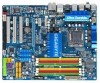
..., check on our website at: http://www.gigabyte.com.tw Identifying Your Motherboard Revision The revision number on your motherboard revision before updating motherboard BIOS, drivers, or when looking for technical information. No part of GIGABYTE. The trademarks mentioned in this manual are legally... registered to the specifications and features in the use GIGABYTE's unique features, read or download the...
..., check on our website at: http://www.gigabyte.com.tw Identifying Your Motherboard Revision The revision number on your motherboard revision before updating motherboard BIOS, drivers, or when looking for technical information. No part of GIGABYTE. The trademarks mentioned in this manual are legally... registered to the specifications and features in the use GIGABYTE's unique features, read or download the...
Manual
Page 4
Table of Contents Box Contents ...6 OptionalItems...6 GA-EP45C-UD3R/UD3 Motherboard Layout 7 Block Diagram...8 Chapter 1 Hardware Installation 9 1-1 Installation Precautions 9 1-2 Product Specifications 10 1-3 Installing the CPU and CPU Cooler...Installing the SATA Bracket 19 1-7 Back Panel Connectors 20 1-8 Internal Connectors 22 Chapter 2 BIOS Setup 35 2-1 Startup Screen 36 2-2 The Main Menu 37 2-3 MB Intelligent Tweaker(M.I.T 39 2-4 Standard CMOS Features 47 2-5 Advanced BIOS Features 49 2-6 IntegratedPeripherals 52 2-7 Power Management Setup 55 2-8 PnP/PCI Configurations 57 ...
Table of Contents Box Contents ...6 OptionalItems...6 GA-EP45C-UD3R/UD3 Motherboard Layout 7 Block Diagram...8 Chapter 1 Hardware Installation 9 1-1 Installation Precautions 9 1-2 Product Specifications 10 1-3 Installing the CPU and CPU Cooler...Installing the SATA Bracket 19 1-7 Back Panel Connectors 20 1-8 Internal Connectors 22 Chapter 2 BIOS Setup 35 2-1 Startup Screen 36 2-2 The Main Menu 37 2-3 MB Intelligent Tweaker(M.I.T 39 2-4 Standard CMOS Features 47 2-5 Advanced BIOS Features 49 2-6 IntegratedPeripherals 52 2-7 Power Management Setup 55 2-8 PnP/PCI Configurations 57 ...

Manual
Page 5
...72 4-2-1 Updating the BIOS with the Q-Flash Utility 72 4-2-2 Updating the BIOS with the @BIOS Utility 75 4-3 EasyTune 6 ...76 4-4 Dynamic Energy Saver Advanced 77 4-5 Q-Share ...79 4-6 Time Repair ...80 Chapter 5 Appendix ...81 5-1 Configuring SATA Hard Drive(s 81 5-1-1 Configuring Intel ICH10R SATA Controllers 81 5-1-2 5-1-3 5-1-4 Configuring GIGABYTE SATA2 SATA Controller 87... 106 5-2-4 Using the Sound Recorder 108 5-3 Troubleshooting 109 5-3-1 Frequently Asked Questions 109 5-3-2 Troubleshooting Procedure 110 5-4 Regulatory Statements 112 Only for GA-EP45C-UD3R. - 5 -
...72 4-2-1 Updating the BIOS with the Q-Flash Utility 72 4-2-2 Updating the BIOS with the @BIOS Utility 75 4-3 EasyTune 6 ...76 4-4 Dynamic Energy Saver Advanced 77 4-5 Q-Share ...79 4-6 Time Repair ...80 Chapter 5 Appendix ...81 5-1 Configuring SATA Hard Drive(s 81 5-1-1 Configuring Intel ICH10R SATA Controllers 81 5-1-2 5-1-3 5-1-4 Configuring GIGABYTE SATA2 SATA Controller 87... 106 5-2-4 Using the Sound Recorder 108 5-3 Troubleshooting 109 5-3-1 Frequently Asked Questions 109 5-3-2 Troubleshooting Procedure 110 5-4 Regulatory Statements 112 Only for GA-EP45C-UD3R. - 5 -

Manual
Page 8
Only for GA-EP45C-UD3R. Block Diagram 1 PCI Express x16 LGA775 Processor CPU CLK+/(400/333/266/200 MHz) PCIe CLK (100 ... x1 x1 PCI Express Bus LAN RJ45 RTL 8111C x1 2 SATA 3Gb/s ATA-133/100/66/ 33 IDE Channel PCI Bus GIGABYTE SATA2 TSB43AB23 3 IEEE 1394a Intel® P45 Dual Channel Memory DDR3 2000/1600/1333/ 1066/800 MHz Dual Channel Memory MCH CLK... (400/333/266/200 MHz) Dual BIOS Intel® ICH10R Intel® ICH10 6 SATA 3Gb/s 12 USB Ports CODEC LPC Bus IT8718 Floppy LPT Port COM Port ...
Only for GA-EP45C-UD3R. Block Diagram 1 PCI Express x16 LGA775 Processor CPU CLK+/(400/333/266/200 MHz) PCIe CLK (100 ... x1 x1 PCI Express Bus LAN RJ45 RTL 8111C x1 2 SATA 3Gb/s ATA-133/100/66/ 33 IDE Channel PCI Bus GIGABYTE SATA2 TSB43AB23 3 IEEE 1394a Intel® P45 Dual Channel Memory DDR3 2000/1600/1333/ 1066/800 MHz Dual Channel Memory MCH CLK... (400/333/266/200 MHz) Dual BIOS Intel® ICH10R Intel® ICH10 6 SATA 3Gb/s 12 USB Ports CODEC LPC Bus IT8718 Floppy LPT Port COM Port ...
Manual
Page 12
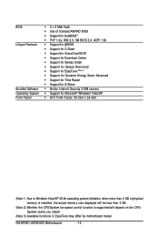
... Software Operating System Form Factor Š 2 x 8 Mbit flash Š Use of licensed AWARD BIOS Š Support for DualBIOSTM Š PnP 1.0a, DMI 2.0, SM BIOS 2.4, ACPI 1.0b Š Support for @BIOS Š Support for Q-Flash Š Support for Virtual Dual BIOS Š Support for Download Center Š Support for Xpress Install Š Support for Xpress... fan speed control function is supported will depend on the CPU/ System cooler you install. (Note 3) Available functions in EasyTune may differ by motherboard model. GA-EP45C-UD3R/UD3 Motherboard - 12 -
... Software Operating System Form Factor Š 2 x 8 Mbit flash Š Use of licensed AWARD BIOS Š Support for DualBIOSTM Š PnP 1.0a, DMI 2.0, SM BIOS 2.4, ACPI 1.0b Š Support for @BIOS Š Support for Q-Flash Š Support for Virtual Dual BIOS Š Support for Download Center Š Support for Xpress Install Š Support for Xpress... fan speed control function is supported will depend on the CPU/ System cooler you install. (Note 3) Available functions in EasyTune may differ by motherboard model. GA-EP45C-UD3R/UD3 Motherboard - 12 -

Manual
Page 16
...; Always turn off the computer and unplug the power cord from the power outlet before installing the memory to be used. (Go to GIGABYTE's website for optimum performance. If you begin to insert the memory, switch the direction. • Mixed mode, populating DDR2 and DDR3 ... be installed in only one DDR2 memory module is installed, the BIOS will automatically detect the specifications and capacity of the same capacity, brand, speed, and chips be populated and remain in Dual Channel mode/performance. GA-EP45C-UD3R/UD3 Motherboard - 16 - Intel® Flex Memory Technology offers...
...; Always turn off the computer and unplug the power cord from the power outlet before installing the memory to be used. (Go to GIGABYTE's website for optimum performance. If you begin to insert the memory, switch the direction. • Mixed mode, populating DDR2 and DDR3 ... be installed in only one DDR2 memory module is installed, the BIOS will automatically detect the specifications and capacity of the same capacity, brand, speed, and chips be populated and remain in Dual Channel mode/performance. GA-EP45C-UD3R/UD3 Motherboard - 16 - Intel® Flex Memory Technology offers...
Manual
Page 18
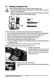
...slot. 1. Align the card with the slot, and press down on the slot and then lift the card straight out from the chassis back panel. 2. GA-EP45C-UD3R/UD3 Motherboard - 18 - Locate an expansion slot that came with your expansion card. • Always turn off the computer and unplug the power cord ... the manual that supports your computer. PCI Express x1 Slot PCI Express x16 Slot PCI Slot Follow the steps below to make any required BIOS changes for your operating system. If necessary, go to BIOS Setup to correctly install your expansion card in your expansion card(s). 7.
...slot. 1. Align the card with the slot, and press down on the slot and then lift the card straight out from the chassis back panel. 2. GA-EP45C-UD3R/UD3 Motherboard - 18 - Locate an expansion slot that came with your expansion card. • Always turn off the computer and unplug the power cord ... the manual that supports your computer. PCI Express x1 Slot PCI Express x16 Slot PCI Slot Follow the steps below to make any required BIOS changes for your operating system. If necessary, go to BIOS Setup to correctly install your expansion card in your expansion card(s). 7.
Manual
Page 28
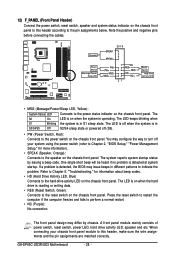
Note the positive and negative pins before connecting the cables. The LED keeps blinking when S1 Blinking the system is detected, the BIOS may issue beeps in S1 sleep state. If a problem is in different patterns to indicate the problem. HD+ 21 Reset Switch ...Speaker Power Switch Message/Power/ Sleep LED 20 19 SPEAK- The LED is on the chassis front panel. GA-EP45C-UD3R/UD3 Motherboard - 28 - When connecting your system using the power switch (refer to Chapter 2, "BIOS Setup," "Power Management Setup," for information about beep codes. • HD (Hard Drive Activity LED, ...
Note the positive and negative pins before connecting the cables. The LED keeps blinking when S1 Blinking the system is detected, the BIOS may issue beeps in S1 sleep state. If a problem is in different patterns to indicate the problem. HD+ 21 Reset Switch ...Speaker Power Switch Message/Power/ Sleep LED 20 19 SPEAK- The LED is on the chassis front panel. GA-EP45C-UD3R/UD3 Motherboard - 28 - When connecting your system using the power switch (refer to Chapter 2, "BIOS Setup," "Power Management Setup," for information about beep codes. • HD (Hard Drive Activity LED, ...
Manual
Page 33
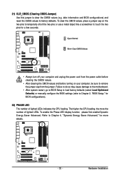
...(refer to Chapter 4, "Dynamic Energy Saver Advanced," for more the number of lighted LEDs indicates the CPU loading. Refer to Chapter 2, "BIOS Setup," for a few seconds. Hardware Installation To enable the Phase LED display function, please first enable Dynamic Energy Saver Advanced. The higher the... details. - 33 - Open: Normal Short: Clear CMOS Values • Always turn off your computer, be sure to touch the two pins for BIOS configurations). 22) PHASE LED The number of lighted LEDs. To clear the CMOS values, place a jumper cap on your computer and unplug the power cord...
...(refer to Chapter 4, "Dynamic Energy Saver Advanced," for more the number of lighted LEDs indicates the CPU loading. Refer to Chapter 2, "BIOS Setup," for a few seconds. Hardware Installation To enable the Phase LED display function, please first enable Dynamic Energy Saver Advanced. The higher the... details. - 33 - Open: Normal Short: Clear CMOS Values • Always turn off your computer, be sure to touch the two pins for BIOS configurations). 22) PHASE LED The number of lighted LEDs. To clear the CMOS values, place a jumper cap on your computer and unplug the power cord...
Manual
Page 34
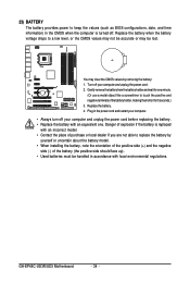
GA-EP45C-UD3R/UD3 Motherboard - 34 - Gently remove the battery from the battery holder and wait for 5 seconds.) 3. Replace the battery. 4. Danger of explosion if the battery is ... battery (the positive side should face up). • Used batteries must be lost. 23) BATTERY The battery provides power to keep the values (such as BIOS configurations, date, and time information) in the CMOS when the computer is replaced with an incorrect model. • Contact the place of purchase or local...
GA-EP45C-UD3R/UD3 Motherboard - 34 - Gently remove the battery from the battery holder and wait for 5 seconds.) 3. Replace the battery. 4. Danger of explosion if the battery is ... battery (the positive side should face up). • Used batteries must be lost. 23) BATTERY The battery provides power to keep the values (such as BIOS configurations, date, and time information) in the CMOS when the computer is replaced with an incorrect model. • Contact the place of purchase or local...

Manual
Page 35
... menu options, you need to) to keep the configuration values in the CMOS. To upgrade the BIOS, use either the GIGABYTE Q-Flash or @BIOS utility. • Q-Flash allows the user to Chapter 4, "BIOS Update Utilities." • Because BIOS flashing is turned on the motherboard. For instructions on the motherboard supplies the necessary power to the...
... menu options, you need to) to keep the configuration values in the CMOS. To upgrade the BIOS, use either the GIGABYTE Q-Flash or @BIOS utility. • Q-Flash allows the user to Chapter 4, "BIOS Update Utilities." • Because BIOS flashing is turned on the motherboard. For instructions on the motherboard supplies the necessary power to the...
Manual
Page 36
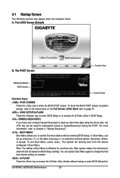
... screen at system startup, refer to the instructions on the Full Screen LOGO Show item on BIOS Setup settings. To exit Boot Menu, press . You can be used for one time only. GA-EP45C-UD3R/UD3 Motherboard - 36 - 2-1 Startup Screen The following screens may appear when the computer boots. ...The POST Screen Award Modular BIOS v6.00PG, An Energy Star Ally Copyright (C) 1984-2008, Award Software, Inc. After ...
... screen at system startup, refer to the instructions on the Full Screen LOGO Show item on BIOS Setup settings. To exit Boot Menu, press . You can be used for one time only. GA-EP45C-UD3R/UD3 Motherboard - 36 - 2-1 Startup Screen The following screens may appear when the computer boots. ...The POST Screen Award Modular BIOS v6.00PG, An Energy Star Ally Copyright (C) 1984-2008, Award Software, Inc. After ...

Manual
Page 37
... system to its defaults. • The BIOS Setup menus described in this chapter are for the menu. BIOS Setup Use arrow keys to move among the items and press to accept or enter a sub-menu. (Sample BIOS Version: GA-EP45C-UD3R E9c) CMOS Setup Utility-Copyright (C) 1984...-2008 Award Software ` MB Intelligent Tweaker(M.I.T.) ` Standard CMOS Features ` Advanced BIOS Features ` Integrated Peripherals ` Power Management Setup ` PnP/PCI Configurations ` PC ...
... system to its defaults. • The BIOS Setup menus described in this chapter are for the menu. BIOS Setup Use arrow keys to move among the items and press to accept or enter a sub-menu. (Sample BIOS Version: GA-EP45C-UD3R E9c) CMOS Setup Utility-Copyright (C) 1984...-2008 Award Software ` MB Intelligent Tweaker(M.I.T.) ` Standard CMOS Features ` Advanced BIOS Features ` Integrated Peripherals ` Power Management Setup ` PnP/PCI Configurations ` PC ...
Manual
Page 38
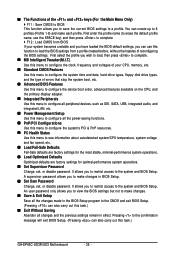
... types, floppy disk drive types, and the type of errors that stop the system boot, etc. „ Advanced BIOS Features Use this menu to configure the device boot order, advanced features available on the CPU, and the primary display... access to make changes. „ Save & Exit Setup Save all changes and the previous settings remain in the BIOS Setup program to see information about autodetected system/CPU temperature, system voltage and fan speed, etc. „ Load ...Password Change, set , or disable password. You can also carry out this task.) GA-EP45C-UD3R/UD3 Motherboard - 38 -
... types, floppy disk drive types, and the type of errors that stop the system boot, etc. „ Advanced BIOS Features Use this menu to configure the device boot order, advanced features available on the CPU, and the primary display... access to make changes. „ Save & Exit Setup Save all changes and the previous settings remain in the BIOS Setup program to see information about autodetected system/CPU temperature, system voltage and fan speed, etc. „ Load ...Password Change, set , or disable password. You can also carry out this task.) GA-EP45C-UD3R/UD3 Motherboard - 38 -

Manual
Page 39
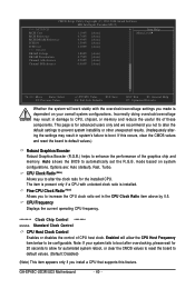
BIOS Setup 2-3 MB Intelligent Tweaker(M.I.T.) CMOS Setup Utility-Copyright (C) 1984-2008 Award Software MB Intelligent Tweaker(M.I.T.) Robust Graphics Booster CPU Clock Ratio (Note 1) Fine CPU Clock ...
BIOS Setup 2-3 MB Intelligent Tweaker(M.I.T.) CMOS Setup Utility-Copyright (C) 1984-2008 Award Software MB Intelligent Tweaker(M.I.T.) Robust Graphics Booster CPU Clock Ratio (Note 1) Fine CPU Clock ...
Manual
Page 40
... the current operating CPU frequency. ******** Clock Chip Control Standard Clock Control CPU Host Clock Control Enables or disables the control of these components. GA-EP45C-UD3R/UD3 Motherboard - 40 - mode based on your system fails to boot after overclocking, please wait for 20 seconds to allow the CPU Host... prevent system instability or other unexpected results. (Inadequately altering the settings may result in system's failure to boot. Auto allows the BIOS to CPU, chipset, or memory and reduce the useful life of CPU host clock. Note: If your overall system configurations.
... the current operating CPU frequency. ******** Clock Chip Control Standard Clock Control CPU Host Clock Control Enables or disables the control of these components. GA-EP45C-UD3R/UD3 Motherboard - 40 - mode based on your system fails to boot after overclocking, please wait for 20 seconds to allow the CPU Host... prevent system instability or other unexpected results. (Inadequately altering the settings may result in system's failure to boot. Auto allows the BIOS to CPU, chipset, or memory and reduce the useful life of CPU host clock. Note: If your overall system configurations.
Manual
Page 41
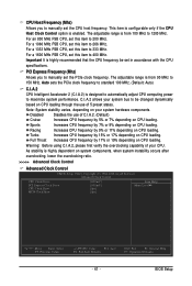
... of 5 preset states. Sports Increases CPU frequency by 5% or 7% depending on CPU loading. Turbo Increases CPU frequency by 15% or 17% depending on CPU loading. BIOS Setup
... of 5 preset states. Sports Increases CPU frequency by 5% or 7% depending on CPU loading. Turbo Increases CPU frequency by 15% or 17% depending on CPU loading. BIOS Setup
Manual
Page 42
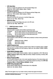
...~750ps. (Default: 0ps) MCH Clock Skew Allows you to set the CPU clock prior to the North Bridge clock. Extreme Memory Profile (X.M.P.) (Note) Allows the BIOS to read the SPD data on CPU FSB and the (G)MCH Frequency Latch settings. Profile2 Uses Profile 2 settings. (G)MCH Frequency Latch Allows you to adjust... item appears only if you to set the North Bridge clock prior to the CPU clock. System Memory Multiplier (SPD) Allows you to be configurable. GA-EP45C-UD3R/UD3 Motherboard - 42 -
...~750ps. (Default: 0ps) MCH Clock Skew Allows you to set the CPU clock prior to the North Bridge clock. Extreme Memory Profile (X.M.P.) (Note) Allows the BIOS to read the SPD data on CPU FSB and the (G)MCH Frequency Latch settings. Profile2 Uses Profile 2 settings. (G)MCH Frequency Latch Allows you to adjust... item appears only if you to set the North Bridge clock prior to the CPU clock. System Memory Multiplier (SPD) Allows you to be configurable. GA-EP45C-UD3R/UD3 Motherboard - 42 -

Manual
Page 43
... : Auto (default), 1~15. tWR Options are : Auto (default), 1~3. ******** ESC: Exit F1: General Help F7: Optimized Defaults - 43 - Command Rate(CMD) Options are : Auto (default), 1~31. BIOS Setup tRP Options are : Auto (default), 1~255. tRFC Options are : Auto (default), 1~15. tWTR Options are : Auto (default), 3~7. >>>>> Standard Timing Control CAS Latency Time Options...
... : Auto (default), 1~15. tWR Options are : Auto (default), 1~3. ******** ESC: Exit F1: General Help F7: Optimized Defaults - 43 - Command Rate(CMD) Options are : Auto (default), 1~31. BIOS Setup tRP Options are : Auto (default), 1~255. tRFC Options are : Auto (default), 1~15. tWTR Options are : Auto (default), 3~7. >>>>> Standard Timing Control CAS Latency Time Options...

Manual
Page 45
... Level Options are : Auto (default), +8~-7. Data Driving Pull-Down Level Options are : Auto (default), +8~-7. Auto Lets the BIOS decide whether to enhance memory compatibility. Data Driving Pull-Up Level Options are : Auto (default), +8~-7. BIOS Setup Enabled Enables this function to enable this function. (Default) Disabled Disables this function. Cmd Driving Pull-Up...
... Level Options are : Auto (default), +8~-7. Data Driving Pull-Down Level Options are : Auto (default), +8~-7. Auto Lets the BIOS decide whether to enhance memory compatibility. Data Driving Pull-Up Level Options are : Auto (default), +8~-7. BIOS Setup Enabled Enables this function to enable this function. (Default) Disabled Disables this function. Cmd Driving Pull-Up...


