Manual
Page 7
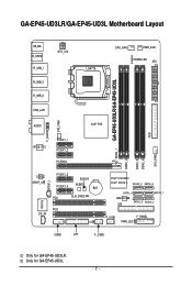
GA-EP45-UD3LR/GA-EP45-UD3L Motherboard Layout KB_MS R_SPDIF R_USB_1 R_USB_2 R_USB_3 ATX_12V LGA775 CPU_FAN PWR_FAN PHASE LED ATX DDR2_1 GA-EP45-UD3LR/GA-EP45-UD3L DDR2_2 DDR2_3 DDR2_4 FDD SYS_FAN2 USB_LAN F_AUDIO SYS_FAN1 AUDIO Intel® P45 RTL8111C PCIEX1_1 PCIEX1_2 PCIEX16 CODEC SPDIF_O SPDIF_I PCIEX1_3 PCIEX1_4 B_BIOS M_BIOS BAT ... CD_IN CI Intel® ICH10R Intel® ICH10 SATA2_3 SATA2_0 SATA2_4 SATA2_ 1 JMicron 368 IDE SATA2_5 SATA2_2 F_USB1 F_PANEL PWR_LED COMA LPT F_USB2 Only for GA-EP45-UD3L. - 7 - Only for GA-EP45-UD3LR.
GA-EP45-UD3LR/GA-EP45-UD3L Motherboard Layout KB_MS R_SPDIF R_USB_1 R_USB_2 R_USB_3 ATX_12V LGA775 CPU_FAN PWR_FAN PHASE LED ATX DDR2_1 GA-EP45-UD3LR/GA-EP45-UD3L DDR2_2 DDR2_3 DDR2_4 FDD SYS_FAN2 USB_LAN F_AUDIO SYS_FAN1 AUDIO Intel® P45 RTL8111C PCIEX1_1 PCIEX1_2 PCIEX16 CODEC SPDIF_O SPDIF_I PCIEX1_3 PCIEX1_4 B_BIOS M_BIOS BAT ... CD_IN CI Intel® ICH10R Intel® ICH10 SATA2_3 SATA2_0 SATA2_4 SATA2_ 1 JMicron 368 IDE SATA2_5 SATA2_2 F_USB1 F_PANEL PWR_LED COMA LPT F_USB2 Only for GA-EP45-UD3L. - 7 - Only for GA-EP45-UD3LR.
Manual
Page 12
... Support for Time Repair Support for Q-Share Norton Internet Security (OEM version) Support for Microsoft® Windows® Vista/XP ATX Form Factor; 30.5cm x 21.0cm (Note 1) Due to Windows Vista/XP 32-bit operating system limitation, when more than 4 GB of physical memory is... CPU/System fan speed control function is supported will depend on the CPU/ System cooler you install. (Note 3) Available functions in EasyTune may differ by motherboard model. GA-EP45-UD3LR/UD3L Motherboard - 12 -
... Support for Time Repair Support for Q-Share Norton Internet Security (OEM version) Support for Microsoft® Windows® Vista/XP ATX Form Factor; 30.5cm x 21.0cm (Note 1) Due to Windows Vista/XP 32-bit operating system limitation, when more than 4 GB of physical memory is... CPU/System fan speed control function is supported will depend on the CPU/ System cooler you install. (Note 3) Available functions in EasyTune may differ by motherboard model. GA-EP45-UD3LR/UD3L Motherboard - 12 -

Manual
Page 21
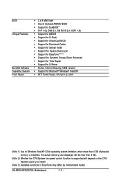
1-7 Internal Connectors 1 35 21 2 10 6 4 4 19 20 14 13 8 12 17 16 18 15 7 9 11 1) ATX_12V 2) ATX 3) CPU_FAN 4) SYS_FAN1/SYS_FAN2 5) PWR_FAN 6) FDD 7) IDE 8) SATA2_0/1/2/3/4/5 9) PWR_LED 10) F_AUDIO 11) F_PANEL 12) CD_IN 13) SPDIF_I 14) SPDIF_O 15) F_USB1/F_USB2 16) LPT 17) COMA ... devices and your devices are compliant with the connectors you wish to connect. • Before installing the devices, be sure to the connector on the motherboard. - 21 - Hardware Installation
1-7 Internal Connectors 1 35 21 2 10 6 4 4 19 20 14 13 8 12 17 16 18 15 7 9 11 1) ATX_12V 2) ATX 3) CPU_FAN 4) SYS_FAN1/SYS_FAN2 5) PWR_FAN 6) FDD 7) IDE 8) SATA2_0/1/2/3/4/5 9) PWR_LED 10) F_AUDIO 11) F_PANEL 12) CD_IN 13) SPDIF_I 14) SPDIF_O 15) F_USB1/F_USB2 16) LPT 17) COMA ... devices and your devices are compliant with the connectors you wish to connect. • Before installing the devices, be sure to the connector on the motherboard. - 21 - Hardware Installation
Manual
Page 22
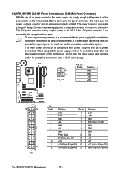
...-12V GND PS_ON(soft On/Off) GND GND GND -5V +5V +5V +5V (Only for 2x12-pinATX) GND (Only for 2x12-pin ATX) GA-EP45-UD3LR/UD3L Motherboard - 22 - The 12V power connector mainly supplies power to the power connector in the correct orientation. Do not insert the power supply cable into ...pins under the protective cover when using a 2x12 power supply, remove the protective cover from the main power connector on the motherboard. Before connecting the power connector, first make sure the power supply is used (500W or greater). The power connector possesses a foolproof design. 1/2)...
...-12V GND PS_ON(soft On/Off) GND GND GND -5V +5V +5V +5V (Only for 2x12-pinATX) GND (Only for 2x12-pin ATX) GA-EP45-UD3LR/UD3L Motherboard - 22 - The 12V power connector mainly supplies power to the power connector in the correct orientation. Do not insert the power supply cable into ...pins under the protective cover when using a 2x12 power supply, remove the protective cover from the main power connector on the motherboard. Before connecting the power connector, first make sure the power supply is used (500W or greater). The power connector possesses a foolproof design. 1/2)...

Manual
Page 54
... On By Mouse Allows the system to be effective. EuP Support Determines whether to let the system consume less than 1W power in a month. GA-EP45-UD3LR/UD3L Motherboard - 54 - HPET Support (Note) Enables or disables High Precision Event Timer (HPET) for Windows® Vista® operating system. (Default:...to select the HPET mode for the password, press again without entering the password to clear the password settings. Note: you need an ATX power supply providing at least 1A on the system, enter the password and press . When prompted for your Windows® Vista®...
... On By Mouse Allows the system to be effective. EuP Support Determines whether to let the system consume less than 1W power in a month. GA-EP45-UD3LR/UD3L Motherboard - 54 - HPET Support (Note) Enables or disables High Precision Event Timer (HPET) for Windows® Vista® operating system. (Default:...to select the HPET mode for the password, press again without entering the password to clear the password settings. Note: you need an ATX power supply providing at least 1A on the system, enter the password and press . When prompted for your Windows® Vista®...

Manual
Page 100
...CPU cooler connected to start the computer. Turn on the CPU. Press to the motherboard. Yes Insert the graphics card. A (Continued...) GA-EP45-UD3LR/UD3L Motherboard - 100 - Yes Check if the memory is attached to the CPU securely. Connect the ATX main power cable and the 12V power cable. Secure the CPU No cooler on the...5-3-2 Troubleshooting Procedure If you encounter any troubles during system startup, follow the troubleshooting procedure below to save changes and exit BIOS Setup. Make sure the motherboard does not short-circuit with the chassis or other metal objects.
...CPU cooler connected to start the computer. Turn on the CPU. Press to the motherboard. Yes Insert the graphics card. A (Continued...) GA-EP45-UD3LR/UD3L Motherboard - 100 - Yes Check if the memory is attached to the CPU securely. Connect the ATX main power cable and the 12V power cable. Secure the CPU No cooler on the...5-3-2 Troubleshooting Procedure If you encounter any troubles during system startup, follow the troubleshooting procedure below to save changes and exit BIOS Setup. Make sure the motherboard does not short-circuit with the chassis or other metal objects.


