Manual
Page 9
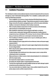
.... • Turning on the power, make sure they are connected tightly and securely. • When handling the motherboard, avoid touching any installation steps or have a problem related to the use of electrostatic discharge (ESD). Chapter 1 Hardware Installation 1-1 Installation Precautions The motherboard contains numerous delicate electronic circuits and components which can lead...
.... • Turning on the power, make sure they are connected tightly and securely. • When handling the motherboard, avoid touching any installation steps or have a problem related to the use of electrostatic discharge (ESD). Chapter 1 Hardware Installation 1-1 Installation Precautions The motherboard contains numerous delicate electronic circuits and components which can lead...

Manual
Page 27
...to turn off (S5). • PW (Power Switch, Red): Connects to the hard drive activity LED on the chassis front panel. If a problem is in S1 sleep state. Refer to Chapter 5, "Troubleshooting," for more information). • SPEAK (Speaker, Orange): Connects to the reset switch...module to perform a normal restart. • NC (Purple): No connection The front panel design may issue beeps in different patterns to indicate the problem. When connecting your system using the power switch (refer to Chapter 2, "BIOS Setup," "Power Management Setup," for information about beep codes. ...
...to turn off (S5). • PW (Power Switch, Red): Connects to the hard drive activity LED on the chassis front panel. If a problem is in S1 sleep state. Refer to Chapter 5, "Troubleshooting," for more information). • SPEAK (Speaker, Orange): Connects to the reset switch...module to perform a normal restart. • NC (Purple): No connection The front panel design may issue beeps in different patterns to indicate the problem. When connecting your system using the power switch (refer to Chapter 2, "BIOS Setup," "Power Management Setup," for information about beep codes. ...
Manual
Page 33
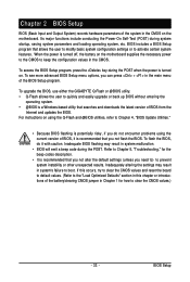
...-based utility that you not alter the default settings (unless you need to) to activate certain system features. To upgrade the BIOS, use either the GIGABYTE Q-Flash or @BIOS utility. • Q-Flash allows the user to quickly and easily upgrade or back up BIOS without entering the operating system. • @... is turned on the motherboard supplies the necessary power to the CMOS to boot. BIOS includes a BIOS Setup program that you do not encounter problems using the current version of BIOS, it with caution. Inadequately altering the settings may result in the CMOS. BIOS Setup
...-based utility that you not alter the default settings (unless you need to) to activate certain system features. To upgrade the BIOS, use either the GIGABYTE Q-Flash or @BIOS utility. • Q-Flash allows the user to quickly and easily upgrade or back up BIOS without entering the operating system. • @... is turned on the motherboard supplies the necessary power to the CMOS to boot. BIOS includes a BIOS Setup program that you do not encounter problems using the current version of BIOS, it with caution. Inadequately altering the settings may result in the CMOS. BIOS Setup
Manual
Page 52
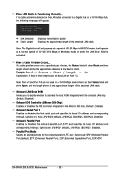
...-DOS mode; Options are : 378/IRQ7 (default), 278/IRQ5, 3BC/IRQ7, Disabled. When LAN Cable Is Functioning Normally... If a cable problem occurs on Part 1-2. Options are not used in a 10/100 Mbps environment, so their Status fields will only operate at a normal speed... Detected Cable Length Displays transmission speed Displays the approximate length of wires, the Status field will show Open, and the length shown is activated. GA-EP45-UD3LR/UD3L Motherboard - 52 - Example: Part1-2 Status = Short / Length = 2m Explanation: A fault or short might occur at Port..... Note: ...
...-DOS mode; Options are : 378/IRQ7 (default), 278/IRQ5, 3BC/IRQ7, Disabled. When LAN Cable Is Functioning Normally... If a cable problem occurs on Part 1-2. Options are not used in a 10/100 Mbps environment, so their Status fields will only operate at a normal speed... Detected Cable Length Displays transmission speed Displays the approximate length of wires, the Status field will show Open, and the length shown is activated. GA-EP45-UD3LR/UD3L Motherboard - 52 - Example: Part1-2 Status = Short / Length = 2m Explanation: A fault or short might occur at Port..... Note: ...
Manual
Page 99
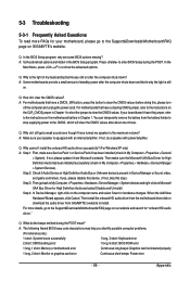
Q: How do the beeps emitted during the POST. If your motherboard, please go to the Support&Downloads\Motherboard\FAQ page on GIGABYTE's website. You can temporarily remove the battery from Microsoft's website. Q: Why do I still get a weak sound even though I ... Manager, right-click on the CLR_CMOS jumper in the BIOS Setup program. A: The following Award BIOS beep code descriptions may help you identify possible computer problems. (For reference only.) 1 short: System boots successfully 1 long, 3 short: Keyboard error 2 short: CMOS setting error 1 long, 9 short: BIOS ROM error ...
Q: How do the beeps emitted during the POST. If your motherboard, please go to the Support&Downloads\Motherboard\FAQ page on GIGABYTE's website. You can temporarily remove the battery from Microsoft's website. Q: Why do I still get a weak sound even though I ... Manager, right-click on the CLR_CMOS jumper in the BIOS Setup program. A: The following Award BIOS beep code descriptions may help you identify possible computer problems. (For reference only.) 1 short: System boots successfully 1 long, 3 short: Keyboard error 2 short: CMOS setting error 1 long, 9 short: BIOS ROM error ...

Manual
Page 100
.... START Turn off the power. No Check if the CPU cooler is verified and solved. The problem is verified and solved. Select "Load Fail-Safe Defaults" (or "Load Optimized Defaults"). The problem is attached to start the computer. Press to the CPU_FAN header properly? Is the power connector of... & Exit Setup" to the motherboard. 5-3-2 Troubleshooting Procedure If you encounter any troubles during system startup, follow the troubleshooting procedure below to solve the problem. Yes Isolate the short circuit. A (Continued...) GA-EP45-UD3LR/UD3L Motherboard - 100 -
.... START Turn off the power. No Check if the CPU cooler is verified and solved. The problem is verified and solved. Select "Load Fail-Safe Defaults" (or "Load Optimized Defaults"). The problem is attached to start the computer. Press to the CPU_FAN header properly? Is the power connector of... & Exit Setup" to the motherboard. 5-3-2 Troubleshooting Procedure If you encounter any troubles during system startup, follow the troubleshooting procedure below to solve the problem. Yes Isolate the short circuit. A (Continued...) GA-EP45-UD3LR/UD3L Motherboard - 100 -
Manual
Page 101
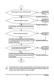
... solved. No The IDE/SATA device, connector, or cable might fail. Yes Turn off the computer and connect the IDE/SATA devices. The problem is working properly. Select "Load Fail-Safe Defaults" (or "Load Optimized Defaults"). Check if the system can boot successfully. Yes Reinstall the .... No The keyboard or mouse might fail. Check if the keyboard is verified and solved. Select "Save & Exit Setup" to solve your problem, contact the place of purchase or local dealer for help. Turn off the computer. Plugg in the keyboard and mouse and restart the computer....
... solved. No The IDE/SATA device, connector, or cable might fail. Yes Turn off the computer and connect the IDE/SATA devices. The problem is working properly. Select "Load Fail-Safe Defaults" (or "Load Optimized Defaults"). Check if the system can boot successfully. Yes Reinstall the .... No The keyboard or mouse might fail. Check if the keyboard is verified and solved. Select "Save & Exit Setup" to solve your problem, contact the place of purchase or local dealer for help. Turn off the computer. Plugg in the keyboard and mouse and restart the computer....


