
Manual
Page 3
... by GIGA-BYTE TECHNOLOGY CO., LTD. Disclaimer Information in this manual may be reproduced, copied, translated, transmitted, or published in the use GIGABYTE's unique features, read or download the information on/from the Support\Motherboard\Technology Guide page on our website. All rights reserved. For example,...132; For detailed product information, carefully read the User's Manual. „ For instructions on your motherboard revision before updating motherboard BIOS, drivers, or when looking for technical information. No part of GIGABYTE branded motherboards. is 1.0.
... by GIGA-BYTE TECHNOLOGY CO., LTD. Disclaimer Information in this manual may be reproduced, copied, translated, transmitted, or published in the use GIGABYTE's unique features, read or download the information on/from the Support\Motherboard\Technology Guide page on our website. All rights reserved. For example,...132; For detailed product information, carefully read the User's Manual. „ For instructions on your motherboard revision before updating motherboard BIOS, drivers, or when looking for technical information. No part of GIGABYTE branded motherboards. is 1.0.

Manual
Page 4
Table of Contents Box Contents ...6 OptionalItems ...6 GA-EP45-DS4P/GA-EP45-DS4 Motherboard Layout 7 Block Diagram ...8 Chapter 1 Hardware Installation 9 1-1 Installation Precautions 9 1-2 Product Specifications 10 1-3 Installing the CPU and CPU Cooler... Panel Connectors 20 1-8 Onboard LEDs and Switches 22 1-9 Internal Connectors 23 Chapter 2 BIOS Setup 35 2-1 Startup Screen 36 2-2 The Main Menu 37 2-3 MB Intelligent Tweaker(M.I.T 39 2-4 Standard CMOS Features 46 2-5 Advanced BIOS Features 48 2-6 IntegratedPeripherals 51 2-7 Power Management Setup 54 2-8 PnP/PCI Configurations 56...
Table of Contents Box Contents ...6 OptionalItems ...6 GA-EP45-DS4P/GA-EP45-DS4 Motherboard Layout 7 Block Diagram ...8 Chapter 1 Hardware Installation 9 1-1 Installation Precautions 9 1-2 Product Specifications 10 1-3 Installing the CPU and CPU Cooler... Panel Connectors 20 1-8 Onboard LEDs and Switches 22 1-9 Internal Connectors 23 Chapter 2 BIOS Setup 35 2-1 Startup Screen 36 2-2 The Main Menu 37 2-3 MB Intelligent Tweaker(M.I.T 39 2-4 Standard CMOS Features 46 2-5 Advanced BIOS Features 48 2-6 IntegratedPeripherals 51 2-7 Power Management Setup 54 2-8 PnP/PCI Configurations 56...

Manual
Page 5
...64 3-4 Contact ...65 3-5 System ...65 3-6 Download Center 66 Chapter 4 Unique Features 67 4-1 Xpress Recovery2 67 4-2 BIOS Update Utilities 72 4-2-1 Updating the BIOS with the Q-Flash Utility 72 4-2-2 Updating the BIOS with the @BIOS Utility 75 4-3 EasyTune 6 ...76 4-4 Dynamic Energy Saver Advanced 77 4-5 Ultra TPM* (Note 79 4-6 Q-Share ...... the Sound Recorder 105 5-3 Troubleshooting 106 5-3-1 Frequently Asked Questions 106 5-3-2 Troubleshooting Procedure 107 Regulatory Statements 109 "*" Only for GA-EP45-DS4P. (Note) This feature is optional due to different regional policy. - 5 -
...64 3-4 Contact ...65 3-5 System ...65 3-6 Download Center 66 Chapter 4 Unique Features 67 4-1 Xpress Recovery2 67 4-2 BIOS Update Utilities 72 4-2-1 Updating the BIOS with the Q-Flash Utility 72 4-2-2 Updating the BIOS with the @BIOS Utility 75 4-3 EasyTune 6 ...76 4-4 Dynamic Energy Saver Advanced 77 4-5 Ultra TPM* (Note 79 4-6 Q-Share ...... the Sound Recorder 105 5-3 Troubleshooting 106 5-3-1 Frequently Asked Questions 106 5-3-2 Troubleshooting Procedure 107 Regulatory Statements 109 "*" Only for GA-EP45-DS4P. (Note) This feature is optional due to different regional policy. - 5 -

Manual
Page 8
... Host Interface DDR2 1200/1066/800/667 MHz Intel® P45 Dual Channel Memory MCH CLK (400/333/266/200 MHz) Intel® ICH10R Dual BIOS 6 SATA 3Gb/s 12 USB Ports CODEC LPC Bus IT8720 Floppy COM Port PS/2 KB/Mouse TPM*(Note) Surround Speaker Out Center/Subwoofer Speaker Out Side... Speaker Out MIC Line-Out Line-In SPDIF In SPDIF Out 1 PCI PCI CLK (33 MHz) "*" Only for GA-EP45-DS4P. (Note) This feature is optional due to different regional policy. - 8 -
... Host Interface DDR2 1200/1066/800/667 MHz Intel® P45 Dual Channel Memory MCH CLK (400/333/266/200 MHz) Intel® ICH10R Dual BIOS 6 SATA 3Gb/s 12 USB Ports CODEC LPC Bus IT8720 Floppy COM Port PS/2 KB/Mouse TPM*(Note) Surround Speaker Out Center/Subwoofer Speaker Out Side... Speaker Out MIC Line-Out Line-In SPDIF In SPDIF Out 1 PCI PCI CLK (33 MHz) "*" Only for GA-EP45-DS4P. (Note) This feature is optional due to different regional policy. - 8 -

Manual
Page 12
... for optimum performance. "*" Only for GA-EP45-DS4P. GA-EP45-DS4P/DS4 Motherboard - 12 - When both of the PCIEX16_1 and PCIEX8_1 slots are installing one PCI Express graphics card, be less than 4 GB of licensed AWARD BIOS Š Support for DualBIOSTM Š PnP 1.0a, DMI 2.0, SM BIOS 2.4, ACPI 1.0b Š Support for @BIOS Š Support for Q-Flash Š...
... for optimum performance. "*" Only for GA-EP45-DS4P. GA-EP45-DS4P/DS4 Motherboard - 12 - When both of the PCIEX16_1 and PCIEX8_1 slots are installing one PCI Express graphics card, be less than 4 GB of licensed AWARD BIOS Š Support for DualBIOSTM Š PnP 1.0a, DMI 2.0, SM BIOS 2.4, ACPI 1.0b Š Support for @BIOS Š Support for Q-Flash Š...

Manual
Page 16
..., and chips be populated and remain in Dual Channel mode/performance. After the memory is installed, the BIOS will double the original memory bandwidth. DS/SS - - Dual Channel mode cannot be used . (Go to GIGABYTE's website for optimum performance. It is recommended that the motherboard supports the memory. DS/SS Four Modules... memory sockets as following: Channel 0: DDR2_1, DDR2_2 Channel 1: DDR2_3, DDR2_4 Dual Channel Memory Configurations Table DDR2_1 DDR2_2 DDR2_3 DDR2_4 Two Modules DS/SS - - DS/SS - - - - GA-EP45-DS4P/DS4 Motherboard - 16 -
..., and chips be populated and remain in Dual Channel mode/performance. After the memory is installed, the BIOS will double the original memory bandwidth. DS/SS - - Dual Channel mode cannot be used . (Go to GIGABYTE's website for optimum performance. It is recommended that the motherboard supports the memory. DS/SS Four Modules... memory sockets as following: Channel 0: DDR2_1, DDR2_2 Channel 1: DDR2_3, DDR2_4 Dual Channel Memory Configurations Table DDR2_1 DDR2_2 DDR2_3 DDR2_4 Two Modules DS/SS - - DS/SS - - - - GA-EP45-DS4P/DS4 Motherboard - 16 -

Manual
Page 18
... press down on the top edge of the slot to make any required BIOS changes for your expansion card in the slot. 3. GA-EP45-DS4P/DS4 Motherboard - 18 - • Removing the Card from the chassis back panel. 2. If necessary, go to BIOS Setup to release the card and then pull the card straight up from...
... press down on the top edge of the slot to make any required BIOS changes for your expansion card in the slot. 3. GA-EP45-DS4P/DS4 Motherboard - 18 - • Removing the Card from the chassis back panel. 2. If necessary, go to BIOS Setup to release the card and then pull the card straight up from...

Manual
Page 22
... has 3 quick switches: power switch, reset switch and clearing CMOS switch, allowing users to improper plug/unplug actions. Power Switch Reset Switch Clearing CMOS Switch GA-EP45-DS4P/DS4 Motherboard - 22 - CPU Memory PCIe x8/x16 PCIe x1/x4 PCI IDE SATA ACPI LEDs The 4 embedded ACPI LEDs indicate the system power status... PCI and PCIe cards and IDE/SATA devices) works abnormally. 1-8 Onboard LEDs and Switches Diagnostic LEDs This motherboard has 7 onboard LEDs controlled by the system BIOS. The LED will light up during the POST when the components/devices have a problem.
... has 3 quick switches: power switch, reset switch and clearing CMOS switch, allowing users to improper plug/unplug actions. Power Switch Reset Switch Clearing CMOS Switch GA-EP45-DS4P/DS4 Motherboard - 22 - CPU Memory PCIe x8/x16 PCIe x1/x4 PCI IDE SATA ACPI LEDs The 4 embedded ACPI LEDs indicate the system power status... PCI and PCIe cards and IDE/SATA devices) works abnormally. 1-8 Onboard LEDs and Switches Diagnostic LEDs This motherboard has 7 onboard LEDs controlled by the system BIOS. The LED will light up during the POST when the components/devices have a problem.

Manual
Page 28
...Status LED S0 On S1 Blinking S3/S4/S5 Off 11) BAT (BATTERY) The battery provides power to keep the values (such as BIOS configurations, date, and time information) in S1 sleep state. Replace the battery when the battery voltage drops to indicate system power status.... local environmental regulations. Definition 1 MPD+ 2 MPD- 1 3 MPD- Turn off your computer and unplug the power cord. 2. Replace the battery. 4. GA-EP45-DS4P/DS4 Motherboard - 28 - Pin No. Gently remove the battery from the battery holder and wait for one . Danger of the battery holder, making them short ...
...Status LED S0 On S1 Blinking S3/S4/S5 Off 11) BAT (BATTERY) The battery provides power to keep the values (such as BIOS configurations, date, and time information) in S1 sleep state. Replace the battery when the battery voltage drops to indicate system power status.... local environmental regulations. Definition 1 MPD+ 2 MPD- 1 3 MPD- Turn off your computer and unplug the power cord. 2. Replace the battery. 4. GA-EP45-DS4P/DS4 Motherboard - 28 - Pin No. Gently remove the battery from the battery holder and wait for one . Danger of the battery holder, making them short ...

Manual
Page 29
...sleep state or powered off your chassis front panel module to this header according to the power switch on when the system is detected, the BIOS may issue beeps in S1 sleep state. 12) F_PANEL (Front Panel Header) Connect the power switch, reset switch, speaker and system status ...is on the chassis front panel. You may differ by issuing a beep code. When connecting your system using the power switch (refer to Chapter 2, "BIOS Setup," "Power Management Setup," for information about beep codes. • HD (Hard Drive Activity LED, Blue) Connects to the power status indicator on ...
...sleep state or powered off your chassis front panel module to this header according to the power switch on when the system is detected, the BIOS may issue beeps in S1 sleep state. 12) F_PANEL (Front Panel Header) Connect the power switch, reset switch, speaker and system status ...is on the chassis front panel. You may differ by issuing a beep code. When connecting your system using the power switch (refer to Chapter 2, "BIOS Setup," "Power Management Setup," for information about beep codes. • HD (Hard Drive Activity LED, Blue) Connects to the power status indicator on ...

Manual
Page 34
... to load factory defaults (select Load Optimized Defaults) or manually configure the BIOS settings (refer to touch the two pins for BIOS configurations). 22) PHASE LED The number of lighted LEDs. GA-EP45-DS4P/DS4 Motherboard - 34 - Open: Normal Short: Clear CMOS Values • Always turn off your computer... the two pins to temporarily short the two pins or use a metal object like a screwdriver to Chapter 2, "BIOS Setup," for a few seconds. date information and BIOS configurations) and reset the CMOS values to clear the CMOS values (e.g. The higher the CPU loading, the more the...
... to load factory defaults (select Load Optimized Defaults) or manually configure the BIOS settings (refer to touch the two pins for BIOS configurations). 22) PHASE LED The number of lighted LEDs. GA-EP45-DS4P/DS4 Motherboard - 34 - Open: Normal Short: Clear CMOS Values • Always turn off your computer... the two pins to temporarily short the two pins or use a metal object like a screwdriver to Chapter 2, "BIOS Setup," for a few seconds. date information and BIOS configurations) and reset the CMOS values to clear the CMOS values (e.g. The higher the CPU loading, the more the...

Manual
Page 35
... the CMOS to keep the configuration values in the CMOS. To upgrade the BIOS, use either the GIGABYTE Q-Flash or @BIOS utility. • Q-Flash allows the user to quickly and easily upgrade or back up BIOS without entering the operating system. • @BIOS is a Windows-based utility that allows the user to modify basic system...
... the CMOS to keep the configuration values in the CMOS. To upgrade the BIOS, use either the GIGABYTE Q-Flash or @BIOS utility. • Q-Flash allows the user to quickly and easily upgrade or back up BIOS without entering the operating system. • @BIOS is a Windows-based utility that allows the user to modify basic system...

Manual
Page 36
... Menu is effective for subsequent access to the instructions on the Full Screen LOGO Show item on BIOS Setup settings. Note: The setting in Boot Menu. The system will still be used for one time only. The LOGO Screen (Default) :POST Screen :BIOS Setup/Q-Flash :XpressRecovery2 :Boot Menu :Qflash B. GA-EP45-DS4P/DS4 Motherboard - 36 -
... Menu is effective for subsequent access to the instructions on the Full Screen LOGO Show item on BIOS Setup settings. Note: The setting in Boot Menu. The system will still be used for one time only. The LOGO Screen (Default) :POST Screen :BIOS Setup/Q-Flash :XpressRecovery2 :Boot Menu :Qflash B. GA-EP45-DS4P/DS4 Motherboard - 36 -

Manual
Page 37
... function keys available for the menu. Help for GA-EP45-DS4P. - 37 - "*" Only for each item is displayed on the right (submenus only) Restore the previous BIOS settings for the current submenus Load the Fail-Safe BIOS default settings for the current submenus Load the Optimized BIOS default settings for the current submenus Access the...
... function keys available for the menu. Help for GA-EP45-DS4P. - 37 - "*" Only for each item is displayed on the right (submenus only) Restore the previous BIOS settings for the current submenus Load the Fail-Safe BIOS default settings for the current submenus Load the Optimized BIOS default settings for the current submenus Access the...

Manual
Page 38
...and date, hard drive types, floppy disk drive types, and the type of errors that stop the system boot, etc. „ Advanced BIOS Features Use this menu to configure the device boot order, advanced features available on the CPU, and the primary display adapter. „ ... the default profile name, use this task.) „ Exit Without Saving Abandon all the changes made in effect. GA-EP45-DS4P/DS4 Motherboard - 38 - Pressing to the confirmation message will exit BIOS Setup. (Pressing can create up to 8 profiles (Profile 1-8) and name each profile. First select the profile you...
...and date, hard drive types, floppy disk drive types, and the type of errors that stop the system boot, etc. „ Advanced BIOS Features Use this menu to configure the device boot order, advanced features available on the CPU, and the primary display adapter. „ ... the default profile name, use this task.) „ Exit Without Saving Abandon all the changes made in effect. GA-EP45-DS4P/DS4 Motherboard - 38 - Pressing to the confirmation message will exit BIOS Setup. (Pressing can create up to 8 profiles (Profile 1-8) and name each profile. First select the profile you...

Manual
Page 39
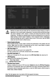
BIOS Setup 2-3 MB Intelligent Tweaker(M.I.T.) CMOS Setup Utility-Copyright (C) 1984-2008 Award Software MB Intelligent Tweaker(M.I.T.) Robust Graphics Booster CPU Clock Ratio (Note 1) Fine CPU Clock ...
BIOS Setup 2-3 MB Intelligent Tweaker(M.I.T.) CMOS Setup Utility-Copyright (C) 1984-2008 Award Software MB Intelligent Tweaker(M.I.T.) Robust Graphics Booster CPU Clock Ratio (Note 1) Fine CPU Clock ...
Manual
Page 40
Auto allows the BIOS to enhance the performance of the graphics chip and memory. mode based on your system fails to boot after overclocking, please wait for 20 seconds ... CPU Host Frequency item below to default values. (Default: Disabled) (Note) This item appears only if you to increase the CPU clock ratio set the R.G.B. GA-EP45-DS4P/DS4 Motherboard - 40 - CMOS Setup Utility-Copyright (C) 1984-2008 Award Software MB Intelligent Tweaker(M.I.T.) >>> MCH/ICH MCH Core MCH Reference MCH/DRAM Reference ICH I/O ICH...
Auto allows the BIOS to enhance the performance of the graphics chip and memory. mode based on your system fails to boot after overclocking, please wait for 20 seconds ... CPU Host Frequency item below to default values. (Default: Disabled) (Note) This item appears only if you to increase the CPU clock ratio set the R.G.B. GA-EP45-DS4P/DS4 Motherboard - 40 - CMOS Setup Utility-Copyright (C) 1984-2008 Award Software MB Intelligent Tweaker(M.I.T.) >>> MCH/ICH MCH Core MCH Reference MCH/DRAM Reference ICH I/O ICH...

Manual
Page 41
... you to manually set this item to 200 MHz. Warning: Before using C.I .A.2. (Default) Cruise Increases CPU frequency by 17% or 19% depending on CPU loading. BIOS Setup
... you to manually set this item to 200 MHz. Warning: Before using C.I .A.2. (Default) Cruise Increases CPU frequency by 17% or 19% depending on CPU loading. BIOS Setup

Manual
Page 42
...the amplitude of the memory being used; System Memory Multiplier (SPD) Allows you to fix the chipset frequency at three different performance levels. GA-EP45-DS4P/DS4 Motherboard - 42 - Standard Lets the system operate at its basic performance level. Options are : 700mV, 800mV, 900mV (default), 1000mV....CPU clock. Options are : 700mV, 800mV (default), 900mV, 1000mV. Disabled Disables this feature. Extreme Memory Profile (X.M.P.) (Note) Allows the BIOS to read the SPD data on CPU FSB and the (G)MCH Frequency Latch settings. Options are : 0ps~750ps. (Default: 0ps) MCH ...
...the amplitude of the memory being used; System Memory Multiplier (SPD) Allows you to fix the chipset frequency at three different performance levels. GA-EP45-DS4P/DS4 Motherboard - 42 - Standard Lets the system operate at its basic performance level. Options are : 700mV, 800mV, 900mV (default), 1000mV....CPU clock. Options are : 700mV, 800mV (default), 900mV, 1000mV. Disabled Disables this feature. Extreme Memory Profile (X.M.P.) (Note) Allows the BIOS to read the SPD data on CPU FSB and the (G)MCH Frequency Latch settings. Options are : 0ps~750ps. (Default: 0ps) MCH ...

Manual
Page 43
ESC: Exit F1: General Help F7: Optimized Defaults BIOS Setup >>>>> Standard Timing Control CAS Latency Time Options are : Auto (default), 1~63. >>>>> Advanced Timing Control Advanced Timing Control CMOS Setup Utility-Copyright (C) 1984-2008 Award ...
ESC: Exit F1: General Help F7: Optimized Defaults BIOS Setup >>>>> Standard Timing Control CAS Latency Time Options are : Auto (default), 1~63. >>>>> Advanced Timing Control Advanced Timing Control CMOS Setup Utility-Copyright (C) 1984-2008 Award ...


