Manual
Page 3
... by GIGA-BYTE TECHNOLOGY CO., LTD as the exclu- Copyright © 2008 GIGA-BYTE TECHNOLOGY CO., LTD. by GIGABYTE without GIGABYTE's prior written permission. Disclaimer Information in this manual may be reproduced, copied, translated, transmitted, or published in this ...GIGABYTE provides the following types of documentations: „ For quick set-up of GIGABYTE. All rights reserved. Changes to use GIGABYTE's unique features, read or download the information on/from the Support\Motherboard\Technology Guide page on your motherboard revision before updating motherboard BIOS...
... by GIGA-BYTE TECHNOLOGY CO., LTD as the exclu- Copyright © 2008 GIGA-BYTE TECHNOLOGY CO., LTD. by GIGABYTE without GIGABYTE's prior written permission. Disclaimer Information in this manual may be reproduced, copied, translated, transmitted, or published in this ...GIGABYTE provides the following types of documentations: „ For quick set-up of GIGABYTE. All rights reserved. Changes to use GIGABYTE's unique features, read or download the information on/from the Support\Motherboard\Technology Guide page on your motherboard revision before updating motherboard BIOS...
Manual
Page 4
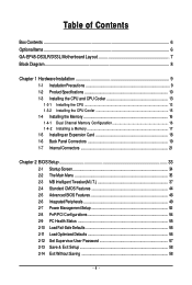
Table of Contents Box Contents ...6 OptionalItems...6 GA-EP45-DS3LR/DS3L Motherboard Layout 7 Block Diagram...8 Chapter 1 Hardware Installation 9 1-1 Installation Precautions 9 1-2 Product Specifications 10 1-3 Installing the CPU and CPU ... Installing an Expansion Card 18 1-6 Back Panel Connectors 19 1-7 Internal Connectors 21 Chapter 2 BIOS Setup 33 2-1 Startup Screen 34 2-2 The Main Menu 35 2-3 MB Intelligent Tweaker(M.I.T 37 2-4 Standard CMOS Features 44 2-5 Advanced BIOS Features 46 2-6 IntegratedPeripherals 49 2-7 Power Management Setup 52 2-8 PnP/PCI Configurations 54 2-9 ...
Table of Contents Box Contents ...6 OptionalItems...6 GA-EP45-DS3LR/DS3L Motherboard Layout 7 Block Diagram...8 Chapter 1 Hardware Installation 9 1-1 Installation Precautions 9 1-2 Product Specifications 10 1-3 Installing the CPU and CPU ... Installing an Expansion Card 18 1-6 Back Panel Connectors 19 1-7 Internal Connectors 21 Chapter 2 BIOS Setup 33 2-1 Startup Screen 34 2-2 The Main Menu 35 2-3 MB Intelligent Tweaker(M.I.T 37 2-4 Standard CMOS Features 44 2-5 Advanced BIOS Features 46 2-6 IntegratedPeripherals 49 2-7 Power Management Setup 52 2-8 PnP/PCI Configurations 54 2-9 ...

Manual
Page 5
...Technical Manuals 60 3-4 Contact ...61 3-5 System ...61 3-6 Download Center 62 Chapter 4 Unique Features 63 4-1 Xpress Recovery2 63 4-2 BIOS Update Utilities 68 4-2-1 Updating the BIOS with the Q-Flash Utility 68 4-2-2 Updating the BIOS with the @BIOS Utility 71 4-3 EasyTune 6 ...72 4-4 Dynamic Energy Saver Advanced 73 4-5 Q-Share ...75 4-6 Time Repair ...76 Chapter 5 Appendix ... Recording 94 5-2-4 Using the Sound Recorder 96 5-3 Troubleshooting 97 5-3-1 Frequently Asked Questions 97 5-3-2 Troubleshooting Procedure 98 5-4 Regulatory Statements 100 Only for GA-EP45-DS3LR. - 5 -
...Technical Manuals 60 3-4 Contact ...61 3-5 System ...61 3-6 Download Center 62 Chapter 4 Unique Features 63 4-1 Xpress Recovery2 63 4-2 BIOS Update Utilities 68 4-2-1 Updating the BIOS with the Q-Flash Utility 68 4-2-2 Updating the BIOS with the @BIOS Utility 71 4-3 EasyTune 6 ...72 4-4 Dynamic Energy Saver Advanced 73 4-5 Q-Share ...75 4-6 Time Repair ...76 Chapter 5 Appendix ... Recording 94 5-2-4 Using the Sound Recorder 96 5-3 Troubleshooting 97 5-3-1 Frequently Asked Questions 97 5-3-2 Troubleshooting Procedure 98 5-4 Regulatory Statements 100 Only for GA-EP45-DS3LR. - 5 -
Manual
Page 8
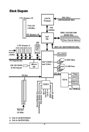
Only for GA-EP45-DS3LR. Block Diagram 1 PCI Express x16 LGA775 Processor CPU CLK+/(400/333/266/200 MHz) PCIe CLK (100 MHz) PCI Express x16 LAN Host Interface Intel&#... Channel Memory PCIe CLK (100 MHz) 4 PCI Express x1 x1 x1 x1 x1 RJ45 RTL 8111C x1 MCH CLK (400/333/266/200 MHz) Dual BIOS PCI Express Bus ATA-133/100/66/ 33 IDE Channel JMicron 368 Intel® ICH10R / Intel® ICH10 6 SATA 3Gb/s 12 USB Ports PCI Bus... Speaker Out Center/Subwoofer Speaker Out Side Speaker Out MIC Line-Out Line-In SPDIF In SPDIF Out 2 PCI PCI CLK (33 MHz) Only for GA-EP45-DS3L. - 8 -
Only for GA-EP45-DS3LR. Block Diagram 1 PCI Express x16 LGA775 Processor CPU CLK+/(400/333/266/200 MHz) PCIe CLK (100 MHz) PCI Express x16 LAN Host Interface Intel&#... Channel Memory PCIe CLK (100 MHz) 4 PCI Express x1 x1 x1 x1 x1 RJ45 RTL 8111C x1 MCH CLK (400/333/266/200 MHz) Dual BIOS PCI Express Bus ATA-133/100/66/ 33 IDE Channel JMicron 368 Intel® ICH10R / Intel® ICH10 6 SATA 3Gb/s 12 USB Ports PCI Bus... Speaker Out Center/Subwoofer Speaker Out Side Speaker Out MIC Line-Out Line-In SPDIF In SPDIF Out 2 PCI PCI CLK (33 MHz) Only for GA-EP45-DS3L. - 8 -
Manual
Page 12
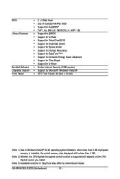
... Software Operating System Form Factor Š 2 x 8 Mbit flash Š Use of licensed AWARD BIOS Š Support for DualBIOSTM Š PnP 1.0a, DMI 2.0, SM BIOS 2.4, ACPI 1.0b Š Support for @BIOS Š Support for Q-Flash Š Support for Virtual Dual BIOS Š Support for Download Center Š Support for Xpress Install Š Support for Xpress... fan speed control function is supported will depend on the CPU/ System cooler you install. (Note 3) Available functions in EasyTune may differ by motherboard model. GA-EP45-DS3LR/DS3L Motherboard - 12 -
... Software Operating System Form Factor Š 2 x 8 Mbit flash Š Use of licensed AWARD BIOS Š Support for DualBIOSTM Š PnP 1.0a, DMI 2.0, SM BIOS 2.4, ACPI 1.0b Š Support for @BIOS Š Support for Q-Flash Š Support for Virtual Dual BIOS Š Support for Download Center Š Support for Xpress Install Š Support for Xpress... fan speed control function is supported will depend on the CPU/ System cooler you install. (Note 3) Available functions in EasyTune may differ by motherboard model. GA-EP45-DS3LR/DS3L Motherboard - 12 -
Manual
Page 16
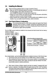
...installing the memory in Dual Channel mode/performance. When enabling Dual Channel mode with two or four memory modules, it is installed, the BIOS will automatically detect the specifications and capacity of the same capacity, brand, speed, and chips be used . (Go to install the .../SS - - - - Dual Channel mode cannot be installed in Flex Memory Mode will appear during the POST. GA-EP45-DS3LR/DS3L Motherboard - 16 - DS/SS - - If you begin to GIGABYTE's website for optimum performance. When memory modules of the same capacity, brand, speed, and chips be populated and ...
...installing the memory in Dual Channel mode/performance. When enabling Dual Channel mode with two or four memory modules, it is installed, the BIOS will automatically detect the specifications and capacity of the same capacity, brand, speed, and chips be used . (Go to install the .../SS - - - - Dual Channel mode cannot be installed in Flex Memory Mode will appear during the POST. GA-EP45-DS3LR/DS3L Motherboard - 16 - DS/SS - - If you begin to GIGABYTE's website for optimum performance. When memory modules of the same capacity, brand, speed, and chips be populated and ...
Manual
Page 18
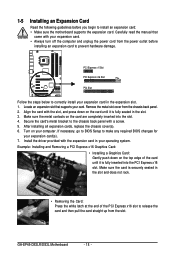
...damage. Carefully read the manual that supports your expansion card(s). 7. Secure the card's metal bracket to make any required BIOS changes for your card. GA-EP45-DS3LR/DS3L Motherboard - 18 - Remove the metal slot cover from the power outlet before you begin to release the card ... • Make sure the motherboard supports the expansion card. Locate an expansion slot that came with a screw. 5. If necessary, go to BIOS Setup to the chassis back panel with your computer. Example: Installing and Removing a PCI Express x16 Graphics Card: • Installing a Graphics Card...
...damage. Carefully read the manual that supports your expansion card(s). 7. Secure the card's metal bracket to make any required BIOS changes for your card. GA-EP45-DS3LR/DS3L Motherboard - 18 - Remove the metal slot cover from the power outlet before you begin to release the card ... • Make sure the motherboard supports the expansion card. Locate an expansion slot that came with a screw. 5. If necessary, go to BIOS Setup to the chassis back panel with your computer. Example: Installing and Removing a PCI Express x16 Graphics Card: • Installing a Graphics Card...
Manual
Page 27
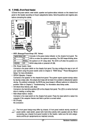
...Speaker, Orange): Connects to the power status indicator on the chassis front panel. When connecting your system using the power switch (refer to Chapter 2, "BIOS Setup," "Power Management Setup," for information about beep codes. • HD (Hard Drive Activity LED, Blue) Connects to the power switch on ... LED on the chassis front panel. Note the positive and negative pins before connecting the cables. The S0 On LED is detected, the BIOS may issue beeps in S1 sleep state. A front panel module mainly consists of power switch, reset switch, power LED, hard drive activity...
...Speaker, Orange): Connects to the power status indicator on the chassis front panel. When connecting your system using the power switch (refer to Chapter 2, "BIOS Setup," "Power Management Setup," for information about beep codes. • HD (Hard Drive Activity LED, Blue) Connects to the power switch on ... LED on the chassis front panel. Note the positive and negative pins before connecting the cables. The S0 On LED is detected, the BIOS may issue beeps in S1 sleep state. A front panel module mainly consists of power switch, reset switch, power LED, hard drive activity...

Manual
Page 31
...values and before turning on the two pins to temporarily short the two pins or use a metal object like a screwdriver to Chapter 2, "BIOS Setup," for a few seconds. Hardware Installation This function requires a chassis with chassis intrusion detection design. To clear the CMOS values, place...may cause damage to the motherboard. • After system restart, go to BIOS Setup to load factory defaults (select Load Optimized Defaults) or manually configure the BIOS settings (refer to touch the two pins for BIOS configurations). - 31 - 18) CI (Chassis Intrusion Header) This motherboard ...
...values and before turning on the two pins to temporarily short the two pins or use a metal object like a screwdriver to Chapter 2, "BIOS Setup," for a few seconds. Hardware Installation This function requires a chassis with chassis intrusion detection design. To clear the CMOS values, place...may cause damage to the motherboard. • After system restart, go to BIOS Setup to load factory defaults (select Load Optimized Defaults) or manually configure the BIOS settings (refer to touch the two pins for BIOS configurations). - 31 - 18) CI (Chassis Intrusion Header) This motherboard ...

Manual
Page 32
...terminals of the battery holder, making them short for more the number of lighted LEDs. The higher the CPU loading, the more details. GA-EP45-DS3LR/DS3L Motherboard - 32 - To enable the Phase LED display function, please first enable Dynamic Energy Saver Advanced. 20) BATTERY The battery provides... power to keep the values (such as BIOS configurations, date, and time information) in the CMOS when the computer is replaced with an incorrect model. • Contact the place ...
...terminals of the battery holder, making them short for more the number of lighted LEDs. The higher the CPU loading, the more details. GA-EP45-DS3LR/DS3L Motherboard - 32 - To enable the Phase LED display function, please first enable Dynamic Energy Saver Advanced. 20) BATTERY The battery provides... power to keep the values (such as BIOS configurations, date, and time information) in the CMOS when the computer is replaced with an incorrect model. • Contact the place ...
Manual
Page 33
...BIOS, use either the GIGABYTE Q-Flash or @BIOS utility. • Q-Flash allows the user to quickly and easily upgrade or back up BIOS without entering the operating system. • @BIOS is a Windows-based utility that you need to) to clear the CMOS values.) - 33 - For instructions on using the Q-Flash and @BIOS utilities, refer to Chapter 4, "BIOS... Refer to Chapter 5, "Troubleshooting," for how to prevent system instability or other unexpected results. BIOS Setup Inadequate BIOS flashing may result in system's failure to keep the configuration values in the CMOS on the ...
...BIOS, use either the GIGABYTE Q-Flash or @BIOS utility. • Q-Flash allows the user to quickly and easily upgrade or back up BIOS without entering the operating system. • @BIOS is a Windows-based utility that you need to) to clear the CMOS values.) - 33 - For instructions on using the Q-Flash and @BIOS utilities, refer to Chapter 4, "BIOS... Refer to Chapter 5, "Troubleshooting," for how to prevent system instability or other unexpected results. BIOS Setup Inadequate BIOS flashing may result in system's failure to keep the configuration values in the CMOS on the ...

Manual
Page 34
...The system will still be used for one time only. EP45-DS3L E12c . . . . : BIOS Setup : XpressRecovery2 : Boot Menu : Qflash 05/20/2008-P45-ICH10-7A89PG0JC-00 Function Keys Function Keys: : POST Screen Press the key to show the BIOS POST screen at system startup, refer to the instructions on... < > or the down arrow key< > to select the first boot device, then press to access the Q-Flash utility directly without entering BIOS Setup. GA-EP45-DS3LR/DS3L Motherboard - 34 - In Boot Menu, use the up hard drive data using the motherboard driver disk, the key can access Boot Menu...
...The system will still be used for one time only. EP45-DS3L E12c . . . . : BIOS Setup : XpressRecovery2 : Boot Menu : Qflash 05/20/2008-P45-ICH10-7A89PG0JC-00 Function Keys Function Keys: : POST Screen Press the key to show the BIOS POST screen at system startup, refer to the instructions on... < > or the down arrow key< > to select the first boot device, then press to access the Q-Flash utility directly without entering BIOS Setup. GA-EP45-DS3LR/DS3L Motherboard - 34 - In Boot Menu, use the up hard drive data using the motherboard driver disk, the key can access Boot Menu...

Manual
Page 35
... of the Main Menu. Help for reference only and may differ by BIOS version. - 35 - Use arrow keys to move among the items and press to accept or enter a sub-menu. (Sample BIOS Version: GA-EP45-DS3L E12c) CMOS Setup Utility-Copyright (C) 1984-2008 Award Software ` ...MB Intelligent Tweaker(M.I.T.) ` Standard CMOS Features ` Advanced BIOS Features ` Integrated Peripherals ` Power Management Setup ` PnP/PCI Configurations ` PC ...
... of the Main Menu. Help for reference only and may differ by BIOS version. - 35 - Use arrow keys to move among the items and press to accept or enter a sub-menu. (Sample BIOS Version: GA-EP45-DS3L E12c) CMOS Setup Utility-Copyright (C) 1984-2008 Award Software ` ...MB Intelligent Tweaker(M.I.T.) ` Standard CMOS Features ` Advanced BIOS Features ` Integrated Peripherals ` Power Management Setup ` PnP/PCI Configurations ` PC ...
Manual
Page 36
... Health Status Use this task.) GA-EP45-DS3LR/DS3L Motherboard - 36 - First select the profile you wish to load, then press to complete. „ MB Intelligent Tweaker(M.I.T.) Use this menu to configure the clock, frequency and voltages of your system becomes unstable and you have loaded the BIOS default settings, you to configure all...
... Health Status Use this task.) GA-EP45-DS3LR/DS3L Motherboard - 36 - First select the profile you wish to load, then press to complete. „ MB Intelligent Tweaker(M.I.T.) Use this menu to configure the clock, frequency and voltages of your system becomes unstable and you have loaded the BIOS default settings, you to configure all...

Manual
Page 37
BIOS Setup 2-3 MB Intelligent Tweaker(M.I.T.) CMOS Setup Utility-Copyright (C) 1984-2008 Award Software MB Intelligent Tweaker(M.I.T.) Robust Graphics Booster CPU Clock Ratio (Note 1) Fine CPU Clock ...
BIOS Setup 2-3 MB Intelligent Tweaker(M.I.T.) CMOS Setup Utility-Copyright (C) 1984-2008 Award Software MB Intelligent Tweaker(M.I.T.) Robust Graphics Booster CPU Clock Ratio (Note 1) Fine CPU Clock ...
Manual
Page 38
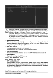
.... ******** Clock Chip Control Standard Clock Control CPU Host Clock Control Enables or disables the control of CPU host clock. Auto allows the BIOS to automatically set in the CPU Clock Ratio item above by 0.5. If this feature. Options are: Auto (default), Fast, Turbo....default settings to prevent system instability or other unexpected results. (Inadequately alter ing the settings may result in system's failure to boot. GA-EP45-DS3LR/DS3L Motherboard - 38 - This page is installed. Incorrectly doing overclock/overvoltage may result in damage to CPU, chipset, or memory ...
.... ******** Clock Chip Control Standard Clock Control CPU Host Clock Control Enables or disables the control of CPU host clock. Auto allows the BIOS to automatically set in the CPU Clock Ratio item above by 0.5. If this feature. Options are: Auto (default), Fast, Turbo....default settings to prevent system instability or other unexpected results. (Inadequately alter ing the settings may result in system's failure to boot. GA-EP45-DS3LR/DS3L Motherboard - 38 - This page is installed. Incorrectly doing overclock/overvoltage may result in damage to CPU, chipset, or memory ...

Manual
Page 39
...) Allows you to maximize system performance. This item is configurable only if the CPU Host Clock Control option is from 90 MHz to 400 MHz. BIOS Setup The adjustable range is enabled.
...) Allows you to maximize system performance. This item is configurable only if the CPU Host Clock Control option is from 90 MHz to 400 MHz. BIOS Setup The adjustable range is enabled.

Manual
Page 40
... prior to the fixed frequency. DRAM Timing Selectable (SPD) Manual allows all DRAM Timing items below may differ according to the North Bridge clock. GA-EP45-DS3LR/DS3L Motherboard - 40 - Options are : Auto (default), 200MHz, 266MHz, 333MHz, 400MHz. Options are: 0ps~750ps. (Default: 0ps) ********... operate at its good performance level. (Default) Lets the system operate at system bootup. Extreme Memory Profile (X.M.P.) (Note) Allows the BIOS to the CPU Host Frequency (Mhz) and System Memory Multiplier settings. Auto sets memory multiplier according to memory SPD data. (Default: ...
... prior to the fixed frequency. DRAM Timing Selectable (SPD) Manual allows all DRAM Timing items below may differ according to the North Bridge clock. GA-EP45-DS3LR/DS3L Motherboard - 40 - Options are : Auto (default), 200MHz, 266MHz, 333MHz, 400MHz. Options are: 0ps~750ps. (Default: 0ps) ********... operate at its good performance level. (Default) Lets the system operate at system bootup. Extreme Memory Profile (X.M.P.) (Note) Allows the BIOS to the CPU Host Frequency (Mhz) and System Memory Multiplier settings. Auto sets memory multiplier according to memory SPD data. (Default: ...

Manual
Page 41
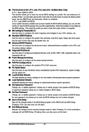
tRP Options are : Auto (default), 1~15. BIOS Setup tRCD Options are : Auto (default), 1~15. tRAS Options are : Auto (default), 3~7. >>>>> Standard Timing Control CAS Latency Time Options are : Auto (default), 1~63. >>>>> Advanced Timing ...
tRP Options are : Auto (default), 1~15. BIOS Setup tRCD Options are : Auto (default), 1~15. tRAS Options are : Auto (default), 3~7. >>>>> Standard Timing Control CAS Latency Time Options are : Auto (default), 1~63. >>>>> Advanced Timing ...

Manual
Page 43
... The default is Auto. ******** - 43 - Twr2rd(Different Rank) Options are : Auto (default), 1~15. ICH I/O The default is Auto. >>> DRAM DRAM Voltage The default is Auto. BIOS Setup Trd2rd(Different Rank) Options are : Auto (default), 0-Normal, 1-Advanced. CPU Reference The default is Auto. >>> MCH/ICH MCH Core The default is Auto. CPU...
... The default is Auto. ******** - 43 - Twr2rd(Different Rank) Options are : Auto (default), 1~15. ICH I/O The default is Auto. >>> DRAM DRAM Voltage The default is Auto. BIOS Setup Trd2rd(Different Rank) Options are : Auto (default), 0-Normal, 1-Advanced. CPU Reference The default is Auto. >>> MCH/ICH MCH Core The default is Auto. CPU...


