Manual
Page 1
GA-EP45-DS3LR/ GA-EP45-DS3L LGA775 socket motherboard for Intel® CoreTM processor family/ Intel® Pentium® processor family/Intel® Celeron® processor family User's Manual Rev. 1005 12ME-EP45DS3L-1005R
GA-EP45-DS3LR/ GA-EP45-DS3L LGA775 socket motherboard for Intel® CoreTM processor family/ Intel® Pentium® processor family/Intel® Celeron® processor family User's Manual Rev. 1005 12ME-EP45DS3L-1005R

Manual
Page 2
Motherboard GA-EP45-DS3LR/GA-EP45-DS3L May 23, 2008 Motherboard GA-EP45-DS3LR/ GA-EP45-DS3L May 23, 2008
Motherboard GA-EP45-DS3LR/GA-EP45-DS3L May 23, 2008 Motherboard GA-EP45-DS3LR/ GA-EP45-DS3L May 23, 2008
Manual
Page 4
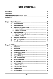
Table of Contents Box Contents ...6 OptionalItems...6 GA-EP45-DS3LR/DS3L Motherboard Layout 7 Block Diagram...8 Chapter 1 Hardware Installation 9 1-1 Installation Precautions 9 1-2 Product Specifications 10 1-3 Installing the CPU and CPU Cooler 13 1-3-1 Installing the CPU 13 1-3-2 Installing the ...
Table of Contents Box Contents ...6 OptionalItems...6 GA-EP45-DS3LR/DS3L Motherboard Layout 7 Block Diagram...8 Chapter 1 Hardware Installation 9 1-1 Installation Precautions 9 1-2 Product Specifications 10 1-3 Installing the CPU and CPU Cooler 13 1-3-1 Installing the CPU 13 1-3-2 Installing the ...

Manual
Page 5
... (Optional 92 5-2-3 Configuring Microphone Recording 94 5-2-4 Using the Sound Recorder 96 5-3 Troubleshooting 97 5-3-1 Frequently Asked Questions 97 5-3-2 Troubleshooting Procedure 98 5-4 Regulatory Statements 100 Only for GA-EP45-DS3LR. - 5 -
... (Optional 92 5-2-3 Configuring Microphone Recording 94 5-2-4 Using the Sound Recorder 96 5-3 Troubleshooting 97 5-3-1 Frequently Asked Questions 97 5-3-2 Troubleshooting Procedure 98 5-4 Regulatory Statements 100 Only for GA-EP45-DS3LR. - 5 -
Manual
Page 6
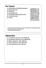
... cable (Part No. 12CR1-1SPDIN-01R) COM port cable (Part No. 12CF1-1CM001-32R) LPT port cable (Part No. 12CF1-1LP001-01R) - 6 - Box Contents GA-EP45-DS3LR or GA-EP45-DS3L motherboard Motherboard driver disk User's Manual Quick Installation Guide One IDE cable and one floppy disk drive cable Two SATA 3Gb/s cables I/O Shield •...
... cable (Part No. 12CR1-1SPDIN-01R) COM port cable (Part No. 12CF1-1CM001-32R) LPT port cable (Part No. 12CF1-1LP001-01R) - 6 - Box Contents GA-EP45-DS3LR or GA-EP45-DS3L motherboard Motherboard driver disk User's Manual Quick Installation Guide One IDE cable and one floppy disk drive cable Two SATA 3Gb/s cables I/O Shield •...
Manual
Page 7
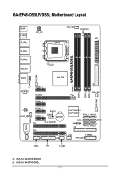
Only for GA-EP45-DS3LR. GA-EP45-DS3LR/DS3L Motherboard Layout KB_MS R_SPDIF R_USB_1 R_USB_2 R_USB_3 ATX_12V CPU_FAN PHASE LED ATX LGA775 DDR2_1 GA-EP45-DS3LR/DS3L DDR2_2 DDR2_3 DDR2_4 FDD SYS_FAN2 USB_LAN AUDIO Intel® P45 F_AUDIO SYS_FAN1 RTL8111C PCIEX1_1 PCIEX16 PCIEX1_2 PWR_FAN CODEC SPDIF_O CD_IN IT8718 SPDIF_I PCIEX1_3 PCIEX1_4 B_BIOS M_BIOS BATTERY PCI1 CLR_CMOS PCI2 CI Intel® ICH10R / Intel® ICH10 SATA2_3 SATA2_0 SATA2_4 SATA2_ 1 JMicron 368 IDE SATA2_5 SATA2_2 F_USB1 F_PANEL PWR_LED COMA LPT F_USB2 Only for GA-EP45-DS3L. - 7 -
Only for GA-EP45-DS3LR. GA-EP45-DS3LR/DS3L Motherboard Layout KB_MS R_SPDIF R_USB_1 R_USB_2 R_USB_3 ATX_12V CPU_FAN PHASE LED ATX LGA775 DDR2_1 GA-EP45-DS3LR/DS3L DDR2_2 DDR2_3 DDR2_4 FDD SYS_FAN2 USB_LAN AUDIO Intel® P45 F_AUDIO SYS_FAN1 RTL8111C PCIEX1_1 PCIEX16 PCIEX1_2 PWR_FAN CODEC SPDIF_O CD_IN IT8718 SPDIF_I PCIEX1_3 PCIEX1_4 B_BIOS M_BIOS BATTERY PCI1 CLR_CMOS PCI2 CI Intel® ICH10R / Intel® ICH10 SATA2_3 SATA2_0 SATA2_4 SATA2_ 1 JMicron 368 IDE SATA2_5 SATA2_2 F_USB1 F_PANEL PWR_LED COMA LPT F_USB2 Only for GA-EP45-DS3L. - 7 -
Manual
Page 8
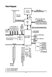
... Speaker Out Center/Subwoofer Speaker Out Side Speaker Out MIC Line-Out Line-In SPDIF In SPDIF Out 2 PCI PCI CLK (33 MHz) Only for GA-EP45-DS3L. - 8 - Only for GA-EP45-DS3LR.
... Speaker Out Center/Subwoofer Speaker Out Side Speaker Out MIC Line-Out Line-In SPDIF In SPDIF Out 2 PCI PCI CLK (33 MHz) Only for GA-EP45-DS3L. - 8 - Only for GA-EP45-DS3LR.

Manual
Page 10
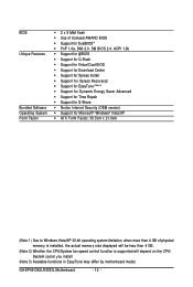
.../ Intel® Pentium® Dual-Core processor/Intel® Celeron® processor in the LGA 775 package (Go to GIGABYTE's website for the latest CPU support list.) Š L2 cache varies with CPU Š 1600/1333/1066/800 MHz ...(Note 1) Š Dual channel memory architecture Š Support for DDR2 1333/1200/1066/800/667 MHz memory modules (Go to GIGABYTE's website for the latest memory support list.) Š Realtek ALC888 codec Š High Definition Audio Š 2/4/5.1/7.1-channel Š... the back panel, 4 via the USB brackets connected to 6 SATA 3Gb/s devices - Only for GA-EP45-DS3L.
.../ Intel® Pentium® Dual-Core processor/Intel® Celeron® processor in the LGA 775 package (Go to GIGABYTE's website for the latest CPU support list.) Š L2 cache varies with CPU Š 1600/1333/1066/800 MHz ...(Note 1) Š Dual channel memory architecture Š Support for DDR2 1333/1200/1066/800/667 MHz memory modules (Go to GIGABYTE's website for the latest memory support list.) Š Realtek ALC888 codec Š High Definition Audio Š 2/4/5.1/7.1-channel Š... the back panel, 4 via the USB brackets connected to 6 SATA 3Gb/s devices - Only for GA-EP45-DS3L.
Manual
Page 12
GA-EP45-DS3LR/DS3L Motherboard - 12 - BIOS Unique Features Bundled Software Operating System Form Factor Š 2 x 8 Mbit flash Š Use of licensed AWARD BIOS Š Support for DualBIOSTM Š ...
GA-EP45-DS3LR/DS3L Motherboard - 12 - BIOS Unique Features Bundled Software Operating System Form Factor Š 2 x 8 Mbit flash Š Use of licensed AWARD BIOS Š Support for DualBIOSTM Š ...

Manual
Page 14
... the load plate and push the CPU socket lever back into the motherboard CPU socket. B. CPU Socket Lever Step 1: Completely raise the CPU socket lever. GA-EP45-DS3LR/DS3L Motherboard - 14 - Before installing the CPU, make sure to the CPU. Align the CPU pin one marking (triangle) with the pin one corner of...
... the load plate and push the CPU socket lever back into the motherboard CPU socket. B. CPU Socket Lever Step 1: Completely raise the CPU socket lever. GA-EP45-DS3LR/DS3L Motherboard - 14 - Before installing the CPU, make sure to the CPU. Align the CPU pin one marking (triangle) with the pin one corner of...
Manual
Page 16
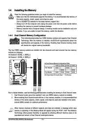
...the memory, switch the direction. 1-4-1 Dual Channel Memory Configuration This motherboard provides four DDR2 memory sockets and supports Dual Channel Technology. GA-EP45-DS3LR/DS3L Motherboard - 16 - 1-4 Installing the Memory Read the following guidelines before you are divided into two channels and each channel has two... DS/SS DS/SS DS/SS (SS=Single-Sided, DS=Double-Sided, "- -"=No Memory) DDR2_1 DDR2_2 DDR2_3 DDR2_4 Due to GIGABYTE's website for optimum performance. When memory modules of the memory. When enabling Dual Channel mode with two or four memory modules, it...
...the memory, switch the direction. 1-4-1 Dual Channel Memory Configuration This motherboard provides four DDR2 memory sockets and supports Dual Channel Technology. GA-EP45-DS3LR/DS3L Motherboard - 16 - 1-4 Installing the Memory Read the following guidelines before you are divided into two channels and each channel has two... DS/SS DS/SS DS/SS (SS=Single-Sided, DS=Double-Sided, "- -"=No Memory) DDR2_1 DDR2_2 DDR2_3 DDR2_4 Due to GIGABYTE's website for optimum performance. When memory modules of the memory. When enabling Dual Channel mode with two or four memory modules, it...
Manual
Page 18
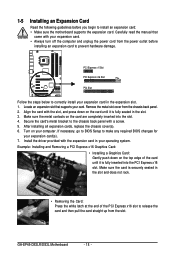
...: • Installing a Graphics Card: Gently push down on your expansion card(s). 7. Turn on the card until it is securely seated in the expansion slot. 1. GA-EP45-DS3LR/DS3L Motherboard - 18 - Carefully read the manual that supports your expansion card. • Always turn off the computer and unplug the power cord from the chassis...
...: • Installing a Graphics Card: Gently push down on your expansion card(s). 7. Turn on the card until it is securely seated in the expansion slot. 1. GA-EP45-DS3LR/DS3L Motherboard - 18 - Carefully read the manual that supports your expansion card. • Always turn off the computer and unplug the power cord from the chassis...
Manual
Page 20
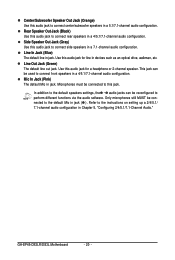
... connected to the instructions on setting up a 2/4/5.1/ 7.1-channel audio configuration in Chapter 5, "Configuring 2/4/5.1/7.1-Channel Audio." Line In Jack (Blue) The default line in jack. GA-EP45-DS3LR/DS3L Motherboard - 20 - Refer to this jack. Microphones must be connected to connect front speakers in a 4/5.1/7.1-channel audio configuration. Center/Subwoofer Speaker Out Jack (Orange) Use...
... connected to the instructions on setting up a 2/4/5.1/ 7.1-channel audio configuration in Chapter 5, "Configuring 2/4/5.1/7.1-Channel Audio." Line In Jack (Blue) The default line in jack. GA-EP45-DS3LR/DS3L Motherboard - 20 - Refer to this jack. Microphones must be connected to connect front speakers in a 4/5.1/7.1-channel audio configuration. Center/Subwoofer Speaker Out Jack (Orange) Use...
Manual
Page 22
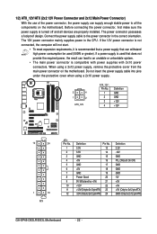
... 3.3V -12V GND PS_ON(soft On/Off) GND GND GND -5V +5V +5V +5V (Only for 2x12-pinATX) GND (Only for 2x12-pin ATX) GA-EP45-DS3LR/DS3L Motherboard - 22 - Do not insert the power supply cable into pins under the protective cover when using a 2x12 power supply, remove the protective cover from...
... 3.3V -12V GND PS_ON(soft On/Off) GND GND GND -5V +5V +5V +5V (Only for 2x12-pinATX) GND (Only for 2x12-pin ATX) GA-EP45-DS3LR/DS3L Motherboard - 22 - Do not insert the power supply cable into pins under the protective cover when using a 2x12 power supply, remove the protective cover from...
Manual
Page 24
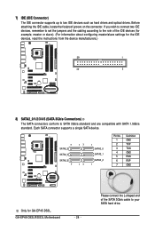
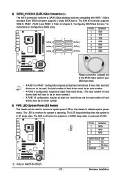
... SATA hard drive. Please connect the L-shaped end of the IDE devices (for example, master or slave). (For information about configuring master/slave settings for GA-EP45-DS3L. GA-EP45-DS3LR/DS3L Motherboard - 24 - 7) IDE (IDE Connector) The IDE connector supports up to two IDE devices such as hard drives and optical drives.
... SATA hard drive. Please connect the L-shaped end of the IDE devices (for example, master or slave). (For information about configuring master/slave settings for GA-EP45-DS3L. GA-EP45-DS3LR/DS3L Motherboard - 24 - 7) IDE (IDE Connector) The IDE connector supports up to two IDE devices such as hard drives and optical drives.
Manual
Page 25
.... 9) PWR_LED (System Power LED Header) This header can be used to connect a system power LED on the chassis to Chapter 5, "Configuring SATA Hard Drive(s)," for GA-EP45-DS3LR. - 25 - The LED is off when the system is operating. Definition 1 MPD+ 1 2 MPD- 3 MPD- Pin No. Refer to indicate system power status. Each SATA...
.... 9) PWR_LED (System Power LED Header) This header can be used to connect a system power LED on the chassis to Chapter 5, "Configuring SATA Hard Drive(s)," for GA-EP45-DS3LR. - 25 - The LED is off when the system is operating. Definition 1 MPD+ 1 2 MPD- 3 MPD- Pin No. Refer to indicate system power status. Each SATA...

Manual
Page 26
... plug. For information about connecting the front panel audio module that has separated connectors on both of the front and back panel audio connections simultaneously. GA-EP45-DS3LR/DS3L Motherboard - 26 - 10) F_AUDIO (Front Panel Audio Header) The front panel audio header supports Intel High Definition audio (HD) and AC'97 audio...
... plug. For information about connecting the front panel audio module that has separated connectors on both of the front and back panel audio connections simultaneously. GA-EP45-DS3LR/DS3L Motherboard - 26 - 10) F_AUDIO (Front Panel Audio Header) The front panel audio header supports Intel High Definition audio (HD) and AC'97 audio...

Manual
Page 28
12) CD_IN (CD In Connector, Black) You may connect the audio cable that came with your optical drive to an audio device that supports digital audio out via an optional S/PDIF in cable. Definition 1 Power 2 SPDIFI 3 GND GA-EP45-DS3LR/DS3L Motherboard - 28 - For purchasing the optional S/PDIF in and can connect to the header. Pin No. Definition 1 CD-L 2 GND 3 GND 4 CD-R 1 13) SPDIF_I (S/PDIF In Header, Red) This header supports digital S/PDIF in cable, please contact the local dealer. 1 Pin No.
12) CD_IN (CD In Connector, Black) You may connect the audio cable that came with your optical drive to an audio device that supports digital audio out via an optional S/PDIF in cable. Definition 1 Power 2 SPDIFI 3 GND GA-EP45-DS3LR/DS3L Motherboard - 28 - For purchasing the optional S/PDIF in and can connect to the header. Pin No. Definition 1 CD-L 2 GND 3 GND 4 CD-R 1 13) SPDIF_I (S/PDIF In Header, Red) This header supports digital S/PDIF in cable, please contact the local dealer. 1 Pin No.

Manual
Page 30
... optional COM port cable, please contact the local dealer. 9 1 10 2 Pin No. 1 2 3 4 5 6 7 8 9 10 Definition NDCD NSIN NSOUT NDTR GND NDSR NRTS NCTS NRI No Pin GA-EP45-DS3LR/DS3L Motherboard - 30 - For purchasing the optional LPT port cable, please contact the local dealer. 25 1 26 Pin No. 1 2 3 4 5 6 7 8 9 10 11 12 13 2 Definition STBAFDPD0...
... optional COM port cable, please contact the local dealer. 9 1 10 2 Pin No. 1 2 3 4 5 6 7 8 9 10 Definition NDCD NSIN NSOUT NDTR GND NDSR NRTS NCTS NRI No Pin GA-EP45-DS3LR/DS3L Motherboard - 30 - For purchasing the optional LPT port cable, please contact the local dealer. 25 1 26 Pin No. 1 2 3 4 5 6 7 8 9 10 11 12 13 2 Definition STBAFDPD0...

Manual
Page 32
... should face up). • Used batteries must be lost. To enable the Phase LED display function, please first enable Dynamic Energy Saver Advanced. Turn off . GA-EP45-DS3LR/DS3L Motherboard - 32 - Replace the battery when the battery voltage drops to Chapter 4, "Dynamic Energy Saver Advanced," for 5 seconds.) 3. Replace the battery. 4. 20) BATTERY The...
... should face up). • Used batteries must be lost. To enable the Phase LED display function, please first enable Dynamic Energy Saver Advanced. Turn off . GA-EP45-DS3LR/DS3L Motherboard - 32 - Replace the battery when the battery voltage drops to Chapter 4, "Dynamic Energy Saver Advanced," for 5 seconds.) 3. Replace the battery. 4. 20) BATTERY The...


