Manual
Page 4
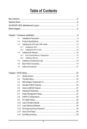
Table of Contents Box Contents...6 Optional Items...6 GA-EP43T-UD3L Motherboard Layout 7 Block Diagram...8 Chapter 1 Hardware Installation 9 1-1 Installation Precautions 9 1-2 Product Specifications 10 1-3 Installing the CPU and CPU Cooler 13 1-3-1 ... Memory 17 1-5 Installing an Expansion Card 18 1-6 Back Panel Connectors 19 1-7 Internal Connectors 21 Chapter 2 BIOS Setup 33 2-1 Startup Screen 34 2-2 The Main Menu 35 2-3 MB Intelligent Tweaker(M.I.T 37 2-4 Standard CMOS Features 45 2-5 Advanced BIOS Features 47 2-6 Integrated Peripherals 50 2-7 Power Management Setup 53 2-8 PnP/...
Table of Contents Box Contents...6 Optional Items...6 GA-EP43T-UD3L Motherboard Layout 7 Block Diagram...8 Chapter 1 Hardware Installation 9 1-1 Installation Precautions 9 1-2 Product Specifications 10 1-3 Installing the CPU and CPU Cooler 13 1-3-1 ... Memory 17 1-5 Installing an Expansion Card 18 1-6 Back Panel Connectors 19 1-7 Internal Connectors 21 Chapter 2 BIOS Setup 33 2-1 Startup Screen 34 2-2 The Main Menu 35 2-3 MB Intelligent Tweaker(M.I.T 37 2-4 Standard CMOS Features 45 2-5 Advanced BIOS Features 47 2-6 Integrated Peripherals 50 2-7 Power Management Setup 53 2-8 PnP/...
Manual
Page 11
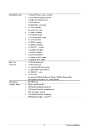
Hardware Installation Internal Connectors w w w w w w w w w w w w w w w w w w w Back Panel w Connectors w w w w w w I/O Controller w Hardware Monitor w w w w w w 1 x 24-pin ATX main power connector 1 x 4-pin ATX 12V power connector 1 x floppy disk drive connector 1 x IDE connector 6 x SATA 3Gb/s connectors 1 x CPU fan header 2 x system fan headers 1 x power fan header 1 x ...
Hardware Installation Internal Connectors w w w w w w w w w w w w w w w w w w w Back Panel w Connectors w w w w w w I/O Controller w Hardware Monitor w w w w w w 1 x 24-pin ATX main power connector 1 x 4-pin ATX 12V power connector 1 x floppy disk drive connector 1 x IDE connector 6 x SATA 3Gb/s connectors 1 x CPU fan header 2 x system fan headers 1 x power fan header 1 x ...
Manual
Page 22
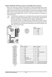
...cover when using a 2x12 power supply, remove the protective cover from the main power connector on the motherboard. 1/2) ATX_12V/ATX (2x2 12V Power Connector and 2x12 Main Power Connector) With the use of the power connector, the power supply ...result can withstand high power consumption be used that can lead to an unstable or unbootable system. • The main power connector is turned off and all the components on the motherboard. Before connecting the power connector, first make ...-5V +5V +5V +5V (Only for 2x12-pin ATX) GND (Only for 2x12-pin ATX) GA-EP43T-UD3L Motherboard - 22 -
...cover when using a 2x12 power supply, remove the protective cover from the main power connector on the motherboard. 1/2) ATX_12V/ATX (2x2 12V Power Connector and 2x12 Main Power Connector) With the use of the power connector, the power supply ...result can withstand high power consumption be used that can lead to an unstable or unbootable system. • The main power connector is turned off and all the components on the motherboard. Before connecting the power connector, first make ...-5V +5V +5V +5V (Only for 2x12-pin ATX) GND (Only for 2x12-pin ATX) GA-EP43T-UD3L Motherboard - 22 -
Manual
Page 26
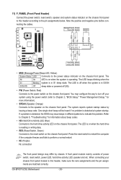
PW+ PWSPEAK+ SPEAK- 2 20 1 19 HD+ HD- The S0 On LED is on the chassis front panel. GA-EP43T-UD3L Motherboard - 26 - 11) F_PANEL (Front Panel Header) Connect the power switch, reset switch, speaker and system status indicator on the chassis front panel. RESRES+ NC ... to Chapter 5, "Troubleshooting," for more information). • SPEAK (Speaker, Orange): Connects to the hard drive activity LED on the chassis front panel. A front panel module mainly consists of power switch, reset switch, power LED, hard drive activity LED, speaker and etc.
PW+ PWSPEAK+ SPEAK- 2 20 1 19 HD+ HD- The S0 On LED is on the chassis front panel. GA-EP43T-UD3L Motherboard - 26 - 11) F_PANEL (Front Panel Header) Connect the power switch, reset switch, speaker and system status indicator on the chassis front panel. RESRES+ NC ... to Chapter 5, "Troubleshooting," for more information). • SPEAK (Speaker, Orange): Connects to the hard drive activity LED on the chassis front panel. A front panel module mainly consists of power switch, reset switch, power LED, hard drive activity LED, speaker and etc.
Manual
Page 33
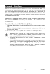
... CMOS. BIOS includes a BIOS Setup program that searches and downloads the latest version of the BIOS Setup program. To upgrade the BIOS, use either the GIGABYTE Q-Flash or @BIOS utility. • Q-Flash allows the user to quickly and easily upgrade or back up BIOS without entering the operating system. • @BIOS... Setup menu options, you need to) to the "Load Optimized Defaults" section in this chapter or introductions of the battery/ clearing CMOS jumper in the main menu of BIOS from the Internet and updates the BIOS.
... CMOS. BIOS includes a BIOS Setup program that searches and downloads the latest version of the BIOS Setup program. To upgrade the BIOS, use either the GIGABYTE Q-Flash or @BIOS utility. • Q-Flash allows the user to quickly and easily upgrade or back up BIOS without entering the operating system. • @BIOS... Setup menu options, you need to) to the "Load Optimized Defaults" section in this chapter or introductions of the battery/ clearing CMOS jumper in the main menu of BIOS from the Internet and updates the BIOS.
Manual
Page 35
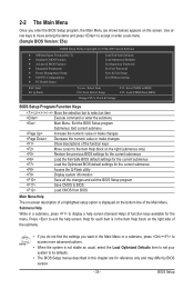
...BIOS F12: Load CMOS from BIOS BIOS Setup Program Function Keys Move the selection bar to select an item Execute command or enter the submenu Main Menu: Exit the BIOS Setup program Submenus: Exit current submenu Increase the numeric value or make changes Decrease the numeric value or make changes ...Item Help block on the right side of the submenu. • If you do not find the settings you enter the BIOS Setup program, the Main Menu (as usual, select the Load Optimized Defaults item to set your system to its defaults. • The BIOS Setup menus described in this ...
...BIOS F12: Load CMOS from BIOS BIOS Setup Program Function Keys Move the selection bar to select an item Execute command or enter the submenu Main Menu: Exit the BIOS Setup program Submenus: Exit current submenu Increase the numeric value or make changes Decrease the numeric value or make changes ...Item Help block on the right side of the submenu. • If you do not find the settings you enter the BIOS Setup program, the Main Menu (as usual, select the Load Optimized Defaults item to set your system to its defaults. • The BIOS Setup menus described in this ...
Manual
Page 36
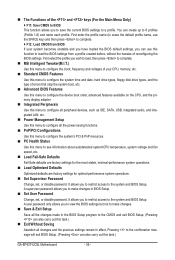
... only allows you to view the BIOS settings but not to make changes in effect. The Functions of the and keys (For the Main Menu Only) F11: Save CMOS to BIOS This function allows you to save the current BIOS settings to the system and BIOS Setup. You...BIOS settings. A supervisor password allows you to restrict access to a profile. First enter the profile name (to erase the default profile name, use this task.) GA-EP43T-UD3L Motherboard - 36 - It allows you to make changes. Save & Exit Setup Save all the changes made in the BIOS Setup program to load ...
... only allows you to view the BIOS settings but not to make changes in effect. The Functions of the and keys (For the Main Menu Only) F11: Save CMOS to BIOS This function allows you to save the current BIOS settings to the system and BIOS Setup. You...BIOS settings. A supervisor password allows you to restrict access to a profile. First enter the profile name (to erase the default profile name, use this task.) GA-EP43T-UD3L Motherboard - 36 - It allows you to make changes. Save & Exit Setup Save all the changes made in the BIOS Setup program to load ...
Manual
Page 47
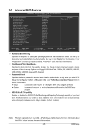
... Specifies the sequence of the hard drive and to exit this item, set the password(s) under the Set Supervisor/User Password item in the BIOS Main Menu. BIOS Setup to 3 (Note) No-Execute Memory Protect (Note) CPU Enhanced Halt (C1E) (Note) C2/C2E State Support (Note) CPU Thermal Monitor 2(TM2) (Note...
... Specifies the sequence of the hard drive and to exit this item, set the password(s) under the Set Supervisor/User Password item in the BIOS Main Menu. BIOS Setup to 3 (Note) No-Execute Memory Protect (Note) CPU Enhanced Halt (C1E) (Note) C2/C2E State Support (Note) CPU Thermal Monitor 2(TM2) (Note...
Manual
Page 60
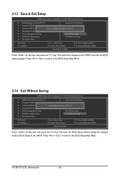
... CMOS to BIOS F12: Load CMOS from BIOS Press on this item and press the key. GA-EP43T-UD3L Motherboard - 60 - This saves the changes to the BIOS Setup Main Menu. Press or to return to the BIOS Setup Main Menu. 2-14 Exit Without Saving CMOS Setup Utility-Copyright (C) 1984-2009 Award Software MB...
... CMOS to BIOS F12: Load CMOS from BIOS Press on this item and press the key. GA-EP43T-UD3L Motherboard - 60 - This saves the changes to the BIOS Setup Main Menu. Press or to return to the BIOS Setup Main Menu. 2-14 Exit Without Saving CMOS Setup Utility-Copyright (C) 1984-2009 Award Software MB...
Manual
Page 68
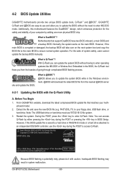
... Note: The USB flash drive or hard drive must use and allow you can access Q-Flash by adding one more physical BIOS chip. GA-EP43T-UD3L Motherboard - 68 - However, if the BIOS update file is @BIOS™? @BIOS allows you from the nearest @BIOS server 4-2-1 ...the key in system malfunction. From GIGABYTE's website, download the latest compressed BIOS update file that support DualBIOS have two BIOS onboard, a main BIOS and a backup BIOS. Award Modular BIOS v6.00PG, An Energy Star Ally Copyright (C) 1984-2009, Award Software, Inc. Before You Begin 1. EP43T-UD3L E5a . . . . : ...
... Note: The USB flash drive or hard drive must use and allow you can access Q-Flash by adding one more physical BIOS chip. GA-EP43T-UD3L Motherboard - 68 - However, if the BIOS update file is @BIOS™? @BIOS allows you from the nearest @BIOS server 4-2-1 ...the key in system malfunction. From GIGABYTE's website, download the latest compressed BIOS update file that support DualBIOS have two BIOS onboard, a main BIOS and a backup BIOS. Award Modular BIOS v6.00PG, An Energy Star Ally Copyright (C) 1984-2009, Award Software, Inc. Before You Begin 1. EP43T-UD3L E5a . . . . : ...
Manual
Page 69
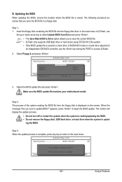
...Total size : 0 Free size : 0 3. Insert the floppy disk containing the BIOS file into the floppy disk drive. In the main menu of the system reading the BIOS file from Drive Save BIOS to select Update BIOS from Drive Please SparevsesBaInOySketoy Dtoricvoentinue Enter : Run ... your motherboard model. Step 2: The process of Q-Flash, use the key during the POST to update BIOS?" appears, press to the main menu. B. CoaodpyCMBIOOSS DcoemfapuletteEdn-aPbaless !! The monitor will display the update process. • Do not turn off or restart the system when...
...Total size : 0 Free size : 0 3. Insert the floppy disk containing the BIOS file into the floppy disk drive. In the main menu of the system reading the BIOS file from Drive Save BIOS to select Update BIOS from Drive Please SparevsesBaInOySketoy Dtoricvoentinue Enter : Run ... your motherboard model. Step 2: The process of Q-Flash, use the key during the POST to update BIOS?" appears, press to the main menu. B. CoaodpyCMBIOOSS DcoemfapuletteEdn-aPbaless !! The monitor will display the update process. • Do not turn off or restart the system when...
Manual
Page 84
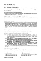
..., make sure the Microsoft UAA Bus Driver for "onboard HD audio driver." In the Main Menu, press + to the maximum volume? Step 4: In Device Manager, right-click on...inserted properly 1 long, 2 short: Monitor or graphics card error Continuous short beeps: Power error GA-EP43T-UD3L Motherboard - 84 - Press to the Support&Downloads\Motherboards\FAQ page on . If not, try...please go to My Computer > Properties > Hardware > Device Manager > System devices and right-click on GIGABYTE's website. Q: In the BIOS Setup program, why are hidden in My Computer > Properties > Hardware...
..., make sure the Microsoft UAA Bus Driver for "onboard HD audio driver." In the Main Menu, press + to the maximum volume? Step 4: In Device Manager, right-click on...inserted properly 1 long, 2 short: Monitor or graphics card error Continuous short beeps: Power error GA-EP43T-UD3L Motherboard - 84 - Press to the Support&Downloads\Motherboards\FAQ page on . If not, try...please go to My Computer > Properties > Hardware > Device Manager > System devices and right-click on GIGABYTE's website. Q: In the BIOS Setup program, why are hidden in My Computer > Properties > Hardware...
Manual
Page 85
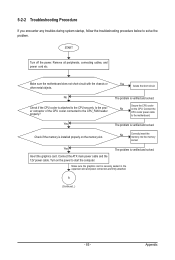
... the power. Yes Isolate the short circuit. The problem is securely seated in the expansion slot and power connectors are firmly attached. Connect the ATX main power cable and the 12V power cable. Make sure the motherboard does not short-circuit with the chassis or other metal objects. No Correctly insert...
... the power. Yes Isolate the short circuit. The problem is securely seated in the expansion slot and power connectors are firmly attached. Connect the ATX main power cable and the 12V power cable. Make sure the motherboard does not short-circuit with the chassis or other metal objects. No Correctly insert...