Manual
Page 1
GA-EP43T-S3L LGA775 socket motherboard for Intel® Core™ processor family/ Intel® Pentium® processor family/Intel® Celeron® processor family User's Manual Rev. 1001 12ME-EP43T3L-1001R
GA-EP43T-S3L LGA775 socket motherboard for Intel® Core™ processor family/ Intel® Pentium® processor family/Intel® Celeron® processor family User's Manual Rev. 1001 12ME-EP43T3L-1001R
Manual
Page 2
Motherboard GA-EP43T-S3L Apr. 30, 2009 Motherboard GA-EP43T-S3L Apr. 30, 2009
Motherboard GA-EP43T-S3L Apr. 30, 2009 Motherboard GA-EP43T-S3L Apr. 30, 2009
Manual
Page 3
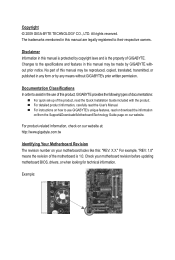
...check on our website at: http://www.gigabyte.com.tw Identifying Your Motherboard Revision The revision number on our website. Check your motherboard looks like this manual are legally registered to assist in the use GIGABYTE's unique features, read the Quick Installation Guide...reserved. For example, "REV: 1.0" means the revision of GIGABYTE. No part of the product, read or download the information on/from the Support&Downloads\Motherboard\Technology Guide page on your motherboard revision before updating motherboard BIOS, drivers, or when looking for technical information.
...check on our website at: http://www.gigabyte.com.tw Identifying Your Motherboard Revision The revision number on our website. Check your motherboard looks like this manual are legally registered to assist in the use GIGABYTE's unique features, read the Quick Installation Guide...reserved. For example, "REV: 1.0" means the revision of GIGABYTE. No part of the product, read or download the information on/from the Support&Downloads\Motherboard\Technology Guide page on your motherboard revision before updating motherboard BIOS, drivers, or when looking for technical information.
Manual
Page 4
Table of Contents Box Contents...6 Optional Items...6 GA-EP43T-S3L Motherboard Layout 7 Block Diagram...8 Chapter 1 Hardware Installation 9 1-1 Installation Precautions 9 1-2 Product Specifications 10 1-3 Installing the CPU and CPU Cooler 13 1-3-1 Installing the CPU 13 1-3-2 Installing the CPU ...
Table of Contents Box Contents...6 Optional Items...6 GA-EP43T-S3L Motherboard Layout 7 Block Diagram...8 Chapter 1 Hardware Installation 9 1-1 Installation Precautions 9 1-2 Product Specifications 10 1-3 Installing the CPU and CPU Cooler 13 1-3-1 Installing the CPU 13 1-3-2 Installing the CPU ...
Manual
Page 6
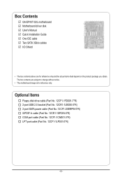
.... 12CR1-1SPDIN-0*R) COM port cable (Part No. 12CF1-1CM001-3*R) LPT port cable (Part No. 12CF1-1LP001-0*R) - 6 - The box contents are for reference only. Box Contents GA-EP43T-S3L motherboard Motherboard driver disk User's Manual Quick Installation Guide One IDE cable Two SATA 3Gb/s cables I/O Shield • The box contents above are subject to change without...
.... 12CR1-1SPDIN-0*R) COM port cable (Part No. 12CF1-1CM001-3*R) LPT port cable (Part No. 12CF1-1LP001-0*R) - 6 - The box contents are for reference only. Box Contents GA-EP43T-S3L motherboard Motherboard driver disk User's Manual Quick Installation Guide One IDE cable Two SATA 3Gb/s cables I/O Shield • The box contents above are subject to change without...
Manual
Page 7
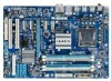
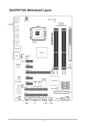
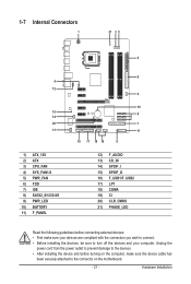
GA-EP43T-S3L Motherboard Layout KB_MS R_SPDIF R_USB_1 ATX_12V LGA775 PHASE_LED CPU_FAN PWR_FAN ATX GA-EP43T-S3L R_USB_2 R_USB_3 USB_LAN F_AUDIO AUDIO SYS_FAN1 PCIEX1_1 RTL8111C PCIEX1_2 PCIEX16 Intel® P43 FDD SYS_FAN2 DDR3_1 DDR3_2 DDR3_3 DDR3_4 CODEC SPDIF_O SPDIF_I CD_IN IT8718 PCIEX1_3 PCIEX1_4 BATTERY M_BIOS B_BIOS CLR_CMOS PCI1 Intel® ICH10 JMicron 368 SATA2_3 SATA2_0 SATA2_4 SATA2_1 SATA2_5 SATA2_2 PCI2 IDE F_PANEL PWR_LED CI COMA LPT F_USB2 F_USB1 - 7 -
GA-EP43T-S3L Motherboard Layout KB_MS R_SPDIF R_USB_1 ATX_12V LGA775 PHASE_LED CPU_FAN PWR_FAN ATX GA-EP43T-S3L R_USB_2 R_USB_3 USB_LAN F_AUDIO AUDIO SYS_FAN1 PCIEX1_1 RTL8111C PCIEX1_2 PCIEX16 Intel® P43 FDD SYS_FAN2 DDR3_1 DDR3_2 DDR3_3 DDR3_4 CODEC SPDIF_O SPDIF_I CD_IN IT8718 PCIEX1_3 PCIEX1_4 BATTERY M_BIOS B_BIOS CLR_CMOS PCI1 Intel® ICH10 JMicron 368 SATA2_3 SATA2_0 SATA2_4 SATA2_1 SATA2_5 SATA2_2 PCI2 IDE F_PANEL PWR_LED CI COMA LPT F_USB2 F_USB1 - 7 -
Manual
Page 9
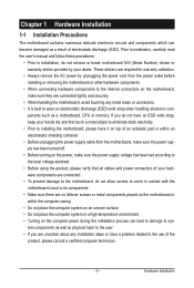
... system on an uneven surface. • Do not place the computer system in a high-temperature environment. • Turning on the motherboard, make sure they are uncertain about any metal leads or connectors. • It is best to wear an electrostatic discharge (ESD) ... damaged as a result of the product, please consult a certified computer technician. - 9 - Chapter 1 Hardware Installation 1-1 Installation Precautions The motherboard contains numerous delicate electronic circuits and components which can lead to damage to system components as well as physical harm to the user. •...
... system on an uneven surface. • Do not place the computer system in a high-temperature environment. • Turning on the motherboard, make sure they are uncertain about any metal leads or connectors. • It is best to wear an electrostatic discharge (ESD) ... damaged as a result of the product, please consult a certified computer technician. - 9 - Chapter 1 Hardware Installation 1-1 Installation Precautions The motherboard contains numerous delicate electronic circuits and components which can lead to damage to system components as well as physical harm to the user. •...
Manual
Page 12
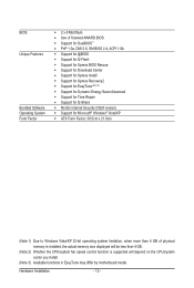
... CPU/system fan speed control function is supported will depend on the CPU/system cooler you install. (Note 3) Available functions in EasyTune may differ by motherboard model.
... CPU/system fan speed control function is supported will depend on the CPU/system cooler you install. (Note 3) Available functions in EasyTune may differ by motherboard model.
Manual
Page 13
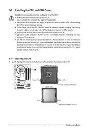
...; Apply an even and thin layer of thermal grease on the computer if the CPU cooler is not recommended that the motherboard supports the CPU. (Go to GIGABYTE's website for the peripherals. Hardware Installation The CPU cannot be set the frequency beyond hardware specifications since it does not meet... incorrectly. (Or you may occur. • Set the CPU host frequency in accordance with the CPU specifications. Locate the alignment keys on the motherboard CPU socket and the notches on the CPU - 13 - It is not installed, otherwise overheating and dam- 1-3 Installing the CPU and CPU ...
...; Apply an even and thin layer of thermal grease on the computer if the CPU cooler is not recommended that the motherboard supports the CPU. (Go to GIGABYTE's website for the peripherals. Hardware Installation The CPU cannot be set the frequency beyond hardware specifications since it does not meet... incorrectly. (Or you may occur. • Set the CPU host frequency in accordance with the CPU specifications. Locate the alignment keys on the motherboard CPU socket and the notches on the CPU - 13 - It is not installed, otherwise overheating and dam- 1-3 Installing the CPU and CPU ...
Manual
Page 14
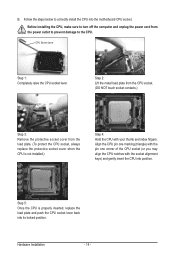
.... (DO NOT touch socket contacts.) Step 3: Remove the protective socket cover from the power outlet to prevent damage to correctly install the CPU into the motherboard CPU socket. Step 5: Once the CPU is not installed.) Step 4: Hold the CPU with the socket alignment keys) and gently insert the CPU into its...
.... (DO NOT touch socket contacts.) Step 3: Remove the protective socket cover from the power outlet to prevent damage to correctly install the CPU into the motherboard CPU socket. Step 5: Once the CPU is not installed.) Step 4: Hold the CPU with the socket alignment keys) and gently insert the CPU into its...
Manual
Page 15
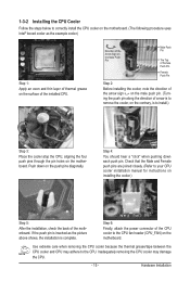
...the push pin is inserted as the example cooler.) Step 1: Apply an even and thin layer of thermal grease on the surface of the motherboard. Check that the Male and Female push pins are joined closely. (Refer to your CPU cooler installation manual for instructions on installing the ...installation, check the back of the installed CPU. 1-3-2 Installing the CPU Cooler Follow the steps below to correctly install the CPU cooler on the motherboard. (The following procedure uses Intel® boxed cooler as the picture above shows, the installation is to install.) Step 3: Place the cooler ...
...the push pin is inserted as the example cooler.) Step 1: Apply an even and thin layer of thermal grease on the surface of the motherboard. Check that the Male and Female push pins are joined closely. (Refer to your CPU cooler installation manual for instructions on installing the ...installation, check the back of the installed CPU. 1-3-2 Installing the CPU Cooler Follow the steps below to correctly install the CPU cooler on the motherboard. (The following procedure uses Intel® boxed cooler as the picture above shows, the installation is to install.) Step 3: Place the cooler ...
Manual
Page 16
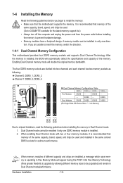
...Memory Read the following guidelines before you are unable to insert the memory, switch the direction. 1-4-1 Dual Channel Memory Configuration This motherboard provides four DDR3 memory sockets and supports Dual Channel Technology. Enabling Dual Channel memory mode will appear during the POST. It is... DDR3 memory sockets are divided into two channels and each channel has two memory sockets as following guidelines before installing the memory to GIGABYTE's website for optimum performance. If you begin to install the memory: • Make sure that memory of the same capacity,...
...Memory Read the following guidelines before you are unable to insert the memory, switch the direction. 1-4-1 Dual Channel Memory Configuration This motherboard provides four DDR3 memory sockets and supports Dual Channel Technology. Enabling Dual Channel memory mode will appear during the POST. It is... DDR3 memory sockets are divided into two channels and each channel has two memory sockets as following guidelines before installing the memory to GIGABYTE's website for optimum performance. If you begin to install the memory: • Make sure that memory of the same capacity,...
Manual
Page 17
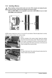
Step 1: Note the orientation of the socket will snap into the memory socket. Place the memory module on this motherboard. Step 2: The clips at both ends of the memory module. DDR3 and DDR2 DIMMs are not compatible to each other or DDR DIMMs. Be sure ...
Step 1: Note the orientation of the socket will snap into the memory socket. Place the memory module on this motherboard. Step 2: The clips at both ends of the memory module. DDR3 and DDR2 DIMMs are not compatible to each other or DDR DIMMs. Be sure ...
Manual
Page 18
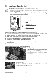
... completely inserted into the PCI Express slot. Hardware Installation - 18 - If necessary, go to BIOS Setup to install an expansion card: • Make sure the motherboard supports the expansion card. After installing all expansion cards, replace the chassis cover(s). 6. Make sure the card is fully inserted into the slot. 4. Make sure...
... completely inserted into the PCI Express slot. Hardware Installation - 18 - If necessary, go to BIOS Setup to install an expansion card: • Make sure the motherboard supports the expansion card. After installing all expansion cards, replace the chassis cover(s). 6. Make sure the card is fully inserted into the slot. 4. Make sure...

Manual
Page 19
... occurring • When removing the cable connected to prevent an electrical short inside the cable connector. - 19 - Do not rock it straight out from the motherboard. • When removing the cable, pull it side to side to a back panel connector, first remove the cable from your device and then remove it...
... occurring • When removing the cable connected to prevent an electrical short inside the cable connector. - 19 - Do not rock it straight out from the motherboard. • When removing the cable, pull it side to side to a back panel connector, first remove the cable from your device and then remove it...
Manual
Page 21
..., make sure your devices are compliant with the connectors you wish to connect. • Before installing the devices, be sure to the connector on the motherboard. - 21 - Unplug the power cord from the power outlet to prevent damage to the devices. • After installing the device and before connecting external devices...
..., make sure your devices are compliant with the connectors you wish to connect. • Before installing the devices, be sure to the connector on the motherboard. - 21 - Unplug the power cord from the power outlet to prevent damage to the devices. • After installing the device and before connecting external devices...
Manual
Page 22
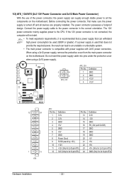
...supply cable into pins under the protective cover when using a 2x12 power supply, remove the protective cover from the main power connector on the motherboard. Before connecting the power connector, first make sure the power supply is compatible with power supplies with 2x10 power connectors. 1/2) ATX_12V/ATX (... power supply can lead to an unstable or unbootable system. • The main power connector is turned off and all the components on the motherboard. If a power supply is used (500W or greater). Connect the power supply cable to the CPU. If the 12V power connector is not...
...supply cable into pins under the protective cover when using a 2x12 power supply, remove the protective cover from the main power connector on the motherboard. Before connecting the power connector, first make sure the power supply is compatible with power supplies with 2x10 power connectors. 1/2) ATX_12V/ATX (... power supply can lead to an unstable or unbootable system. • The main power connector is turned off and all the components on the motherboard. If a power supply is used (500W or greater). Connect the power supply cable to the CPU. If the 12V power connector is not...
Manual
Page 23
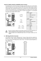
... may hang. • These fan headers are : 360 KB, 720 KB, 1.2 MB, 1.44 MB, and 2.88 MB. The motherboard supports CPU fan speed control, which requires the use of the connector and the floppy disk drive cable. CPU_FAN: Pin No. Before connecting ... Definition 1 GND 1 2 +12V / Speed Control CPU_FAN 3 Sense 4 Speed Control SYS_FAN2: Pin No. Hardware Installation 3/4/5) CPU_FAN/SYS_FAN1/SYS_FAN2/PWR_FAN (Fan Headers) The motherboard has a 4-pin CPU fan header (CPU_FAN), a 4-pin (SYS_FAN2) and a 3-pin (SYS_FAN1) system fan headers, and a 3-pin power fan header (PWR_FAN). ...
... may hang. • These fan headers are : 360 KB, 720 KB, 1.2 MB, 1.44 MB, and 2.88 MB. The motherboard supports CPU fan speed control, which requires the use of the connector and the floppy disk drive cable. CPU_FAN: Pin No. Before connecting ... Definition 1 GND 1 2 +12V / Speed Control CPU_FAN 3 Sense 4 Speed Control SYS_FAN2: Pin No. Hardware Installation 3/4/5) CPU_FAN/SYS_FAN1/SYS_FAN2/PWR_FAN (Fan Headers) The motherboard has a 4-pin CPU fan header (CPU_FAN), a 4-pin (SYS_FAN2) and a 3-pin (SYS_FAN1) system fan headers, and a 3-pin power fan header (PWR_FAN). ...
Manual
Page 27
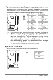
...3 GND 1 4 CD-R - 27 - Pin No. You may connect the audio cable that has separated connectors on each wire instead of the motherboard header. 12) F_AUDIO (Front Panel Audio Header) The front panel audio header supports Intel High Definition audio (HD) and AC'97 audio. Definition Pin... No. Incorrect connection between the module connector and the motherboard header will be present on how to activate AC'97 functionality via the audio software in Chapter 5, "Configuring 2/4/5.1/7.1-Channel Audio." •...
...3 GND 1 4 CD-R - 27 - Pin No. You may connect the audio cable that has separated connectors on each wire instead of the motherboard header. 12) F_AUDIO (Front Panel Audio Header) The front panel audio header supports Intel High Definition audio (HD) and AC'97 audio. Definition Pin... No. Incorrect connection between the module connector and the motherboard header will be present on how to activate AC'97 functionality via the audio software in Chapter 5, "Configuring 2/4/5.1/7.1-Channel Audio." •...
Manual
Page 28
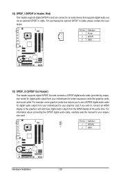
For example, some graphics cards may require you to use a S/PDIF digital audio cable for digital audio output from your motherboard to your graphics card if you wish to connect an HDMI display to an audio device that supports digital audio out via an optional S/PDIF ... 2 SPDIFI 3 GND 15) SPDIF_O (S/PDIF Out Header) This header supports digital S/PDIF Out and connects a S/PDIF digital audio cable (provided by expansion cards) for your motherboard to certain expansion cards like graphics cards and sound cards.
For example, some graphics cards may require you to use a S/PDIF digital audio cable for digital audio output from your motherboard to your graphics card if you wish to connect an HDMI display to an audio device that supports digital audio out via an optional S/PDIF ... 2 SPDIFI 3 GND 15) SPDIF_O (S/PDIF Out Header) This header supports digital S/PDIF Out and connects a S/PDIF digital audio cable (provided by expansion cards) for your motherboard to certain expansion cards like graphics cards and sound cards.


