Manual
Page 3
... in this manual may be reproduced, copied, translated, transmitted, or published in the use GIGABYTE's unique features, read the User's Manual. Example: Check your motherboard looks like this product, GIGABYTE provides the following types of documentations: For quick set-up of this : "REV: X.X." For instructions on your motherboard revision before updating motherboard BIOS, drivers, or when looking for technical information. Copyright © 2009 GIGA-BYTE TECHNOLOGY CO...
... in this manual may be reproduced, copied, translated, transmitted, or published in the use GIGABYTE's unique features, read the User's Manual. Example: Check your motherboard looks like this product, GIGABYTE provides the following types of documentations: For quick set-up of this : "REV: X.X." For instructions on your motherboard revision before updating motherboard BIOS, drivers, or when looking for technical information. Copyright © 2009 GIGA-BYTE TECHNOLOGY CO...
Manual
Page 4
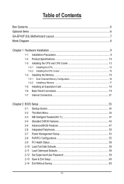
Table of Contents Box Contents...6 Optional Items...6 GA-EP43T-S3L Motherboard Layout 7 Block Diagram...8 Chapter 1 Hardware Installation 9 1-1 Installation Precautions 9 1-2 Product Specifications 10 1-3 Installing the CPU and CPU Cooler 13 1-3-1 Installing the CPU 13 1-3-2 Installing the CPU Cooler 15 1-4 Installing the Memory 16 1-4-1 Dual Channel Memory Configuration 16 1-4-2 Installing a Memory 17 1-5 Installing an Expansion Card 18 1-6 Back Panel Connectors 19 1-7 Internal Connectors 21 Chapter 2 BIOS Setup 33 2-1 Startup Screen 34 2-2 The Main Menu 35 2-3 MB Intelligent ...
Table of Contents Box Contents...6 Optional Items...6 GA-EP43T-S3L Motherboard Layout 7 Block Diagram...8 Chapter 1 Hardware Installation 9 1-1 Installation Precautions 9 1-2 Product Specifications 10 1-3 Installing the CPU and CPU Cooler 13 1-3-1 Installing the CPU 13 1-3-2 Installing the CPU Cooler 15 1-4 Installing the Memory 16 1-4-1 Dual Channel Memory Configuration 16 1-4-2 Installing a Memory 17 1-5 Installing an Expansion Card 18 1-6 Back Panel Connectors 19 1-7 Internal Connectors 21 Chapter 2 BIOS Setup 33 2-1 Startup Screen 34 2-2 The Main Menu 35 2-3 MB Intelligent ...
Manual
Page 11
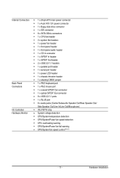
... x 24-pin ATX main power connector 1 x 4-pin ATX 12V power connector 1 x floppy disk drive connector 1 x IDE connector 6 x SATA 3Gb/s connectors 1 x CPU fan header 2 x system fan headers 1 x power fan header 1 x front panel header 1 x front panel audio header 1 x CD In connector 1 x S/PDIF In header 1 x S/PDIF Out header 2 x USB 2.0/1.1 headers 1 x parallel port header 1 x serial port header 1 x power LED header 1 x chassis intrusion header 1 x clearing CMOS jumper 1 x PS/2 keyboard port 1 x PS/2 mouse port 1 x coaxial S/PDIF Out connector 1 x optical S/PDIF Out connector 8 x USB 2.0/1.1 ports...
... x 24-pin ATX main power connector 1 x 4-pin ATX 12V power connector 1 x floppy disk drive connector 1 x IDE connector 6 x SATA 3Gb/s connectors 1 x CPU fan header 2 x system fan headers 1 x power fan header 1 x front panel header 1 x front panel audio header 1 x CD In connector 1 x S/PDIF In header 1 x S/PDIF Out header 2 x USB 2.0/1.1 headers 1 x parallel port header 1 x serial port header 1 x power LED header 1 x chassis intrusion header 1 x clearing CMOS jumper 1 x PS/2 keyboard port 1 x PS/2 mouse port 1 x coaxial S/PDIF Out connector 1 x optical S/PDIF Out connector 8 x USB 2.0/1.1 ports...
Manual
Page 16
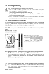
... Memory Technology offers greater flexibility to upgrade by allowing different memory sizes to be used . (Go to GIGABYTE's website for optimum performance. Hardware Installation - 16 - Dual Channel mode cannot be installed in the same colored DDR3 sockets for the latest memory support list.) • Always turn off the computer and unplug the power cord from the power outlet before installing the memory in Dual Channel mode/performance. Enabling Dual Channel memory mode will appear during the POST. DS/SS - - When enabling Dual Channel mode...
... Memory Technology offers greater flexibility to upgrade by allowing different memory sizes to be used . (Go to GIGABYTE's website for optimum performance. Hardware Installation - 16 - Dual Channel mode cannot be installed in the same colored DDR3 sockets for the latest memory support list.) • Always turn off the computer and unplug the power cord from the power outlet before installing the memory in Dual Channel mode/performance. Enabling Dual Channel memory mode will appear during the POST. DS/SS - - When enabling Dual Channel mode...
Manual
Page 18
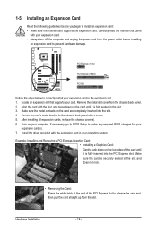
.... After installing all expansion cards, replace the chassis cover(s). 6. Install the driver provided with a screw. 5. If necessary, go to BIOS Setup to the chassis back panel with the expansion card in your expansion card in the slot. 3. Secure the card's metal bracket to make any required BIOS changes for your card. Locate an expansion slot that came with the slot, and press down on your expansion card. • Always turn off the...
.... After installing all expansion cards, replace the chassis cover(s). 6. Install the driver provided with a screw. 5. If necessary, go to BIOS Setup to the chassis back panel with the expansion card in your expansion card in the slot. 3. Secure the card's metal bracket to make any required BIOS changes for your card. Locate an expansion slot that came with the slot, and press down on your expansion card. • Always turn off the...
Manual
Page 23
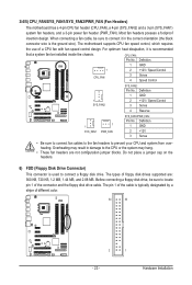
... motherboard has a 4-pin CPU fan header (CPU_FAN), a 4-pin (SYS_FAN2) and a 3-pin (SYS_FAN1) system fan headers, and a 3-pin power fan header (PWR_FAN). The motherboard supports CPU fan speed control, which requires the use of floppy disk drives supported are not configuration jumper blocks. Definition 1 GND 2 +12V 3 Sense • Be sure to connect fan cables to the fan headers to the CPU or the system may hang. • These fan headers are : 360 KB, 720 KB, 1.2 MB, 1.44 MB, and 2.88 MB. Before connecting a floppy disk drive, be sure to locate pin...
... motherboard has a 4-pin CPU fan header (CPU_FAN), a 4-pin (SYS_FAN2) and a 3-pin (SYS_FAN1) system fan headers, and a 3-pin power fan header (PWR_FAN). The motherboard supports CPU fan speed control, which requires the use of floppy disk drives supported are not configuration jumper blocks. Definition 1 GND 2 +12V 3 Sense • Be sure to connect fan cables to the fan headers to the CPU or the system may hang. • These fan headers are : 360 KB, 720 KB, 1.2 MB, 1.44 MB, and 2.88 MB. Before connecting a floppy disk drive, be sure to locate pin...
Manual
Page 31
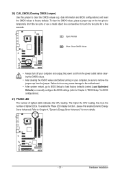
... lighted LEDs indicates the CPU loading. 20) CLR_CMOS (Clearing CMOS Jumper) Use this jumper to touch the two pins for a few seconds. Failure to do so may cause damage to the motherboard. • After system restart, go to BIOS Setup to load factory defaults (select Load Optimized Defaults) or manually configure the BIOS settings (refer to factory defaults. Hardware Installation date information and BIOS configurations) and reset the CMOS values to Chapter 2, "BIOS Setup," for BIOS configurations). 21) PHASE LED The number of lighted LEDs...
... lighted LEDs indicates the CPU loading. 20) CLR_CMOS (Clearing CMOS Jumper) Use this jumper to touch the two pins for a few seconds. Failure to do so may cause damage to the motherboard. • After system restart, go to BIOS Setup to load factory defaults (select Load Optimized Defaults) or manually configure the BIOS settings (refer to factory defaults. Hardware Installation date information and BIOS configurations) and reset the CMOS values to Chapter 2, "BIOS Setup," for BIOS configurations). 21) PHASE LED The number of lighted LEDs...
Manual
Page 33
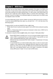
... 5, "Troubleshooting," for how to clear the CMOS values.) - 33 - If this chapter or introductions of the BIOS Setup program. BIOS Setup To upgrade the BIOS, use either the GIGABYTE Q-Flash or @BIOS utility. • Q-Flash allows the user to quickly and easily upgrade or back up BIOS without entering the operating system. • @BIOS is a Windows-based utility that you not alter the default settings (unless you can press + in the main menu of the battery/ clearing CMOS jumper in...
... 5, "Troubleshooting," for how to clear the CMOS values.) - 33 - If this chapter or introductions of the BIOS Setup program. BIOS Setup To upgrade the BIOS, use either the GIGABYTE Q-Flash or @BIOS utility. • Q-Flash allows the user to quickly and easily upgrade or back up BIOS without entering the operating system. • @BIOS is a Windows-based utility that you not alter the default settings (unless you can press + in the main menu of the battery/ clearing CMOS jumper in...
Manual
Page 34
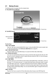
... - Motherboard Model BIOS Version EP43T-S3L E1a . . . . : BIOS Setup : XpressRecovery2 : Boot Menu : Qflash 10/15/2009-P43-ICH10-7A69PG0TC-00 Function Keys Function Keys Function Keys: : POST SCREEN Press the key to show the BIOS POST screen at system startup, refer to access the Q-Flash utility directly without entering BIOS Setup. The POST Screen Award Modular BIOS v6.00PG, An Energy Star Ally Copyright (C) 1984-2009, Award Software, Inc. In Boot Menu, use the up arrow key or the down arrow key to select the first boot device...
... - Motherboard Model BIOS Version EP43T-S3L E1a . . . . : BIOS Setup : XpressRecovery2 : Boot Menu : Qflash 10/15/2009-P43-ICH10-7A69PG0TC-00 Function Keys Function Keys Function Keys: : POST SCREEN Press the key to show the BIOS POST screen at system startup, refer to access the Q-Flash utility directly without entering BIOS Setup. The POST Screen Award Modular BIOS v6.00PG, An Energy Star Ally Copyright (C) 1984-2009, Award Software, Inc. In Boot Menu, use the up arrow key or the down arrow key to select the first boot device...
Manual
Page 36
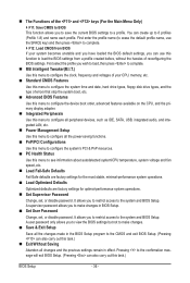
... device boot order, advanced features available on the CPU, and the primary display adapter. Integrated Peripherals Use this menu to configure all peripheral devices, such as IDE, SATA, USB, integrated audio, and integrated LAN, etc. Power Management Setup Use this menu to configure all changes and the previous settings remain in effect. First enter the profile name (to erase the default profile name, use this function to load the BIOS settings from BIOS If your CPU, memory...
... device boot order, advanced features available on the CPU, and the primary display adapter. Integrated Peripherals Use this menu to configure all peripheral devices, such as IDE, SATA, USB, integrated audio, and integrated LAN, etc. Power Management Setup Use this menu to configure all changes and the previous settings remain in effect. First enter the profile name (to erase the default profile name, use this function to load the BIOS settings from BIOS If your CPU, memory...
Manual
Page 38
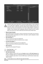
... board to default values. (Default: Disabled) (Note) This item appears only if you install a CPU that supports this occurs, clear the CMOS values and reset the board to default values.) Robust Graphics Booster Robust Graphics Booster (R.G.B.) helps to enhance the performance of the graphics chip and memory. CMOS Setup Utility-Copyright (C) 1984-2009 Award Software MB Intelligent Tweaker(M.I.T.) MCH Core MCH Reference ICH I/O 1.100V 0.760V 1.550V [Auto] [Auto] [Auto] Item Help Menu Level ICH Core 1.100V [Auto] >>> DRAM DRAM Voltage 1.500V [Auto] DRAM...
... board to default values. (Default: Disabled) (Note) This item appears only if you install a CPU that supports this occurs, clear the CMOS values and reset the board to default values.) Robust Graphics Booster Robust Graphics Booster (R.G.B.) helps to enhance the performance of the graphics chip and memory. CMOS Setup Utility-Copyright (C) 1984-2009 Award Software MB Intelligent Tweaker(M.I.T.) MCH Core MCH Reference ICH I/O 1.100V 0.760V 1.550V [Auto] [Auto] [Auto] Item Help Menu Level ICH Core 1.100V [Auto] >>> DRAM DRAM Voltage 1.500V [Auto] DRAM...
Manual
Page 44
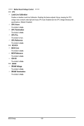
... The default is Auto. Enabling this feature adjusts Vdroop, keeping the CPU voltage more constant under light and heavy CPU load. Disabled sets the CPU voltage following Intel specifications. (Default: Disabled) CPU Vcore The default is Auto. ICH I/O The default is Auto. >>> DRAM DRAM Voltage The default is Auto. CPU Termination The default is Auto. BIOS Setup - 44 - CPU Reference The default is Auto. >>> MCH/ICH MCH Core The default is Auto. ******** Mother Board Voltage Control CPU Load-Line Calibration Enables or disables Load-Line Calibration. CPU PLL The default is Auto...
... The default is Auto. Enabling this feature adjusts Vdroop, keeping the CPU voltage more constant under light and heavy CPU load. Disabled sets the CPU voltage following Intel specifications. (Default: Disabled) CPU Vcore The default is Auto. ICH I/O The default is Auto. >>> DRAM DRAM Voltage The default is Auto. CPU Termination The default is Auto. BIOS Setup - 44 - CPU Reference The default is Auto. >>> MCH/ICH MCH Core The default is Auto. ******** Mother Board Voltage Control CPU Load-Line Calibration Enables or disables Load-Line Calibration. CPU PLL The default is Auto...
Manual
Page 47
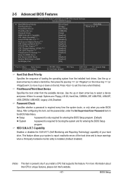
... for entering the BIOS Setup program. (Default) System A password is required every time the system boots, or only when you install a CPU that supports this item, set the password(s) under the Set Supervisor/User Password item in the BIOS Main Menu. BIOS Setup This feature allows your hard drive. 2-5 Advanced BIOS Features CMOS Setup Utility-Copyright (C) 1984-2009 Award Software Advanced BIOS Features } Hard Disk Boot Priority First Boot Device Second Boot Device Third Boot Device Password Check HDD S.M.A.R.T. Press to report read/write errors of loading...
... for entering the BIOS Setup program. (Default) System A password is required every time the system boots, or only when you install a CPU that supports this item, set the password(s) under the Set Supervisor/User Password item in the BIOS Main Menu. BIOS Setup This feature allows your hard drive. 2-5 Advanced BIOS Features CMOS Setup Utility-Copyright (C) 1984-2009 Award Software Advanced BIOS Features } Hard Disk Boot Priority First Boot Device Second Boot Device Third Boot Device Password Check HDD S.M.A.R.T. Press to report read/write errors of loading...

Manual
Page 50
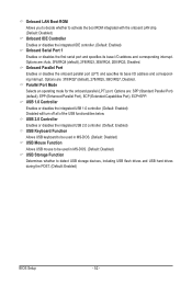
... Peripherals CMOS Setup Utility-Copyright (C) 1984-2009 Award Software Integrated Peripherals SATA Port0-3 Native Mode Azalia Codec Onboard H/W LAN Green LAN } SMART LAN Onboard LAN Boot ROM Onboard IDE Controller Onboard Serial Port 1 Onboard Parallel Port Parallel Port Mode USB 1.0 Controller USB 2.0 Controller USB Keyboard Function USB Mouse Function USB Storage Function [Disabled] [Auto] [Enabled] [Disabled] [Press Enter] [Disabled] [Enabled] [3F8/IRQ4] [378/IRQ7] [SPP] [Enabled] [Enabled] [Disabled] [Disabled] [Enabled] Item Help Menu...
... Peripherals CMOS Setup Utility-Copyright (C) 1984-2009 Award Software Integrated Peripherals SATA Port0-3 Native Mode Azalia Codec Onboard H/W LAN Green LAN } SMART LAN Onboard LAN Boot ROM Onboard IDE Controller Onboard Serial Port 1 Onboard Parallel Port Parallel Port Mode USB 1.0 Controller USB 2.0 Controller USB Keyboard Function USB Mouse Function USB Storage Function [Disabled] [Auto] [Enabled] [Disabled] [Press Enter] [Disabled] [Enabled] [3F8/IRQ4] [378/IRQ7] [SPP] [Enabled] [Enabled] [Disabled] [Disabled] [Enabled] Item Help Menu...
Manual
Page 52
... onboard LAN chip. (Default: Disabled) Onboard IDE Controller Enables or disables the integrated IDE controller. (Default: Enabled) Onboard Serial Port 1 Enables or disables the first serial port and specifies its base I /O address and corresponding interrupt. Options are : 378/IRQ7 (default), 278/IRQ5, 3BC/IRQ7, Disabled. Parallel Port Mode Selects an operating mode for the onboard parallel (LPT) port. Onboard LAN Boot ROM Allows you to decide whether to detect USB storage devices, including USB flash drives and USB hard drives during the POST. (Default: Enabled) BIOS Setup - 52 - USB...
... onboard LAN chip. (Default: Disabled) Onboard IDE Controller Enables or disables the integrated IDE controller. (Default: Enabled) Onboard Serial Port 1 Enables or disables the first serial port and specifies its base I /O address and corresponding interrupt. Options are : 378/IRQ7 (default), 278/IRQ5, 3BC/IRQ7, Disabled. Parallel Port Mode Selects an operating mode for the onboard parallel (LPT) port. Onboard LAN Boot ROM Allows you to decide whether to detect USB storage devices, including USB flash drives and USB hard drives during the POST. (Default: Enabled) BIOS Setup - 52 - USB...
Manual
Page 56
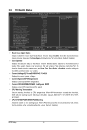
..." at next boot. (Default: Disabled) Case Opened Displays the detection status of previous chassis intrusion status. CPU Warning Temperature Sets the warning threshold for CPU temperature. CPU/SYSTEM/POWER FAN Fail Warning Allows the system to the motherboard CI header. When CPU temperature exceeds the threshold, BIOS will show "Yes", otherwise it will emit warning sound. To clear the chassis intrusion status record, set Reset Case Open Status to Enabled, save the settings to the CMOS, and then...
..." at next boot. (Default: Disabled) Case Opened Displays the detection status of previous chassis intrusion status. CPU Warning Temperature Sets the warning threshold for CPU temperature. CPU/SYSTEM/POWER FAN Fail Warning Allows the system to the motherboard CI header. When CPU temperature exceeds the threshold, BIOS will show "Yes", otherwise it will emit warning sound. To clear the chassis intrusion status record, set Reset Case Open Status to Enabled, save the settings to the CMOS, and then...
Manual
Page 61
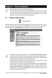
... in the motherboard driver disk. • For USB 2.0 driver support under the Windows XP operating system, please install the Windows XP Service Pack 1 or later. After installing the SP1 (or later), if a question mark still exists in Universal Serial Bus Controller in the screen shot below. (If the driver Autorun screen does not appear automatically, go to restart your system and then list all the recommended drivers. the Found...
... in the motherboard driver disk. • For USB 2.0 driver support under the Windows XP operating system, please install the Windows XP Service Pack 1 or later. After installing the SP1 (or later), if a question mark still exists in Universal Serial Bus Controller in the screen shot below. (If the driver Autorun screen does not appear automatically, go to restart your system and then list all the recommended drivers. the Found...
Manual
Page 68
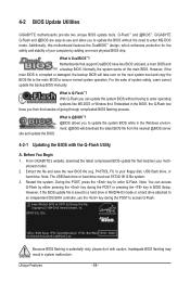
... is Q-Flash™? Note: The USB flash drive or hard drive must use the key during the POST or pressing the key in the Windows environment. @BIOS will take over on the main BIOS. Embedded in system malfunction. site and update the BIOS. What is potentially risky, please do it with the Q-Flash Utility A. From GIGABYTE's website, download the latest compressed BIOS update file that support DualBIOS have two BIOS onboard, a main BIOS and a backup BIOS. EP43T-S3L E1a . . . . : BIOS Setup : XpressRecovery2 : Boot Menu : Qflash...
... is Q-Flash™? Note: The USB flash drive or hard drive must use the key during the POST or pressing the key in the Windows environment. @BIOS will take over on the main BIOS. Embedded in system malfunction. site and update the BIOS. What is potentially risky, please do it with the Q-Flash Utility A. From GIGABYTE's website, download the latest compressed BIOS update file that support DualBIOS have two BIOS onboard, a main BIOS and a backup BIOS. EP43T-S3L E1a . . . . : BIOS Setup : XpressRecovery2 : Boot Menu : Qflash...
Manual
Page 69
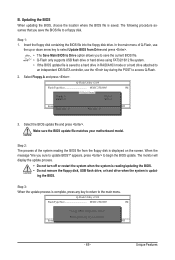
... a hard drive in RAID/AHCI mode or a hard drive attached to an independent IDE/SATA controller, use the up or down arrow key to select Update BIOS from Drive Save BIOS to the main menu. Insert the floppy disk containing the BIOS file into the floppy disk drive. ing the BIOS. Q-Flash Utility v2.09 Flash Type/Size MXIC 25L8005 1M Keep DMI Data Enable !L! Select Floppy A and press . Update BIOS from the floppy disk is complete, press any key to return to Drive Enter : Run hi:Move ESC:Reset F10:Power...
... a hard drive in RAID/AHCI mode or a hard drive attached to an independent IDE/SATA controller, use the up or down arrow key to select Update BIOS from Drive Save BIOS to the main menu. Insert the floppy disk containing the BIOS file into the floppy disk drive. ing the BIOS. Q-Flash Utility v2.09 Flash Type/Size MXIC 25L8005 1M Keep DMI Data Enable !L! Select Floppy A and press . Update BIOS from the floppy disk is complete, press any key to return to Drive Enter : Run hi:Move ESC:Reset F10:Power...
Manual
Page 84
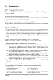
... Award BIOS beep code descriptions may help you identify possible computer problems. (For reference only.) 1 short: System boots successfully 1 long, 3 short: Keyboard error 2 short: CMOS setting error 1 long, 9 short: BIOS ROM error 1 long, 1 short: Memory or motherboard error Continuous long beeps: Graphics card not inserted properly 1 long, 2 short: Monitor or graphics card error Continuous short beeps: Power error Appendix - 84 - Press to show the advanced options. Q: How do the beeps emitted during the POST. Q: Why cannot I clear the CMOS values? Step 4: In Device...
... Award BIOS beep code descriptions may help you identify possible computer problems. (For reference only.) 1 short: System boots successfully 1 long, 3 short: Keyboard error 2 short: CMOS setting error 1 long, 9 short: BIOS ROM error 1 long, 1 short: Memory or motherboard error Continuous long beeps: Graphics card not inserted properly 1 long, 2 short: Monitor or graphics card error Continuous short beeps: Power error Appendix - 84 - Press to show the advanced options. Q: How do the beeps emitted during the POST. Q: Why cannot I clear the CMOS values? Step 4: In Device...


