
Manual
Page 1
GA-EP43-UD3L/ GA-EP43-US3L LGA775 socket motherboard for Intel® CoreTM processor family/ Intel® Pentium® processor family/Intel® Celeron® processor family User's Manual Rev. 1201 12ME-EP43UD3L-1201R
GA-EP43-UD3L/ GA-EP43-US3L LGA775 socket motherboard for Intel® CoreTM processor family/ Intel® Pentium® processor family/Intel® Celeron® processor family User's Manual Rev. 1201 12ME-EP43UD3L-1201R
Manual
Page 2
Motherboard GA-EP43-UD3L/GA-EP43-US3L Dec. 12, 2008 Motherboard GA-EP43-UD3L/ GA-EP43-US3L Dec. 12, 2008
Motherboard GA-EP43-UD3L/GA-EP43-US3L Dec. 12, 2008 Motherboard GA-EP43-UD3L/ GA-EP43-US3L Dec. 12, 2008
Manual
Page 3
... in this manual may be made by any form or by GIGABYTE without GIGABYTE's prior written permission. For product-related information, check on our website at: http://www.gigabyte.com.tw Identifying Your Motherboard Revision The revision number on your motherboard revision before updating motherboard BIOS, drivers, or when looking for technical information. All rights reserved...
... in this manual may be made by any form or by GIGABYTE without GIGABYTE's prior written permission. For product-related information, check on our website at: http://www.gigabyte.com.tw Identifying Your Motherboard Revision The revision number on your motherboard revision before updating motherboard BIOS, drivers, or when looking for technical information. All rights reserved...

Manual
Page 4
Table of Contents Box Contents ...6 OptionalItems...6 GA-EP43-UD3L/US3L Motherboard Layout 7 Block Diagram...8 Chapter 1 Hardware Installation 9 1-1 Installation Precautions 9 1-2 Product Specifications 10 1-3 Installing the CPU and CPU Cooler 13 1-3-1 Installing the CPU 13 1-3-2 Installing the CPU ...
Table of Contents Box Contents ...6 OptionalItems...6 GA-EP43-UD3L/US3L Motherboard Layout 7 Block Diagram...8 Chapter 1 Hardware Installation 9 1-1 Installation Precautions 9 1-2 Product Specifications 10 1-3 Installing the CPU and CPU Cooler 13 1-3-1 Installing the CPU 13 1-3-2 Installing the CPU ...

Manual
Page 6
Box Contents GA-EP43-UD3L or GA-EP43-US3L motherboard Motherboard driver disk User's Manual Quick Installation Guide One IDE cable Two SATA 3Gb/s cables I/O Shield • The box contents above are subject to change without notice. • The motherboard image is for reference only and the actual items shall depend on product package you obtain. The box contents...
Box Contents GA-EP43-UD3L or GA-EP43-US3L motherboard Motherboard driver disk User's Manual Quick Installation Guide One IDE cable Two SATA 3Gb/s cables I/O Shield • The box contents above are subject to change without notice. • The motherboard image is for reference only and the actual items shall depend on product package you obtain. The box contents...

Manual
Page 7
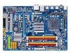
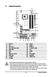
Only for GA-EP43-UD3L. GA-EP43-UD3L/US3L Motherboard Layout GA-EP43-UD3L/US3L PHASE LED FDD KB_MS R_SPDIF COAXIAL R_USB_1 R_USB_2 R_USB_3 ATX_12V LGA775 CPU_FAN PWR_FAN ATX USB_LAN F_AUDIO SYS_FAN1 AUDIO Intel® P43 RTL8111C PCIEX1_1 PCIEX1_2 DDR2_1 ... M_BIOS BATTERY PCI1 CLR_CMOS PCI2 CI Intel® ICH10 SATA2_3 SATA2_0 SATA2_4 SATA2_ 1 JMicron 368 IDE SATA2_5 SATA2_2 F_USB1 F_PANEL PWR_LED COMA LPT F_USB2 "*" The GA-EP43-UD3L adopts All-Solid Capacitor design. Only for GA-EP43-US3L. - 7 -
Only for GA-EP43-UD3L. GA-EP43-UD3L/US3L Motherboard Layout GA-EP43-UD3L/US3L PHASE LED FDD KB_MS R_SPDIF COAXIAL R_USB_1 R_USB_2 R_USB_3 ATX_12V LGA775 CPU_FAN PWR_FAN ATX USB_LAN F_AUDIO SYS_FAN1 AUDIO Intel® P43 RTL8111C PCIEX1_1 PCIEX1_2 DDR2_1 ... M_BIOS BATTERY PCI1 CLR_CMOS PCI2 CI Intel® ICH10 SATA2_3 SATA2_0 SATA2_4 SATA2_ 1 JMicron 368 IDE SATA2_5 SATA2_2 F_USB1 F_PANEL PWR_LED COMA LPT F_USB2 "*" The GA-EP43-UD3L adopts All-Solid Capacitor design. Only for GA-EP43-US3L. - 7 -
Manual
Page 9
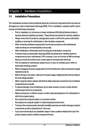
... manual and follow these procedures: • Prior to wear an electrostatic discharge (ESD) wrist strap when handling electronic components such as a motherboard, CPU or memory. Hardware Installation These stickers are required for warranty validation. • Always remove the AC power by unplugging the power...dealer. If you are uncertain about any metal leads or connectors. • It is best to installation, do not remove or break motherboard S/N (Serial Number) sticker or warranty sticker provided by your hands dry and first touch a metal object to eliminate static electricity. •...
... manual and follow these procedures: • Prior to wear an electrostatic discharge (ESD) wrist strap when handling electronic components such as a motherboard, CPU or memory. Hardware Installation These stickers are required for warranty validation. • Always remove the AC power by unplugging the power...dealer. If you are uncertain about any metal leads or connectors. • It is best to installation, do not remove or break motherboard S/N (Serial Number) sticker or warranty sticker provided by your hands dry and first touch a metal object to eliminate static electricity. •...

Manual
Page 10
GA-EP43-UD3L/US3L Motherboard - 10 - 1-2 Product Specifications CPU Front Side Bus Chipset Memory Audio LAN...174; Pentium® Dual-Core processor/Intel® Celeron® processor in the LGA 775 package (Go to GIGABYTE's website for the latest CPU support list.) L2 cache varies with CPU 1600(O.C.)/1333/1066/800... 1) Dual channel memory architecture Support for DDR2 1200/1066/800/667 MHz memory modules (Go to GIGABYTE's website for the latest memory support list.) Realtek ALC888 codec High Definition Audio 2/4/5.1/7.1-channel ...
GA-EP43-UD3L/US3L Motherboard - 10 - 1-2 Product Specifications CPU Front Side Bus Chipset Memory Audio LAN...174; Pentium® Dual-Core processor/Intel® Celeron® processor in the LGA 775 package (Go to GIGABYTE's website for the latest CPU support list.) L2 cache varies with CPU 1600(O.C.)/1333/1066/800... 1) Dual channel memory architecture Support for DDR2 1200/1066/800/667 MHz memory modules (Go to GIGABYTE's website for the latest memory support list.) Realtek ALC888 codec High Definition Audio 2/4/5.1/7.1-channel ...

Manual
Page 12
... CPU/System fan speed control function is supported will depend on the CPU/ System cooler you install. (Note 3) Available functions in EasyTune may differ by motherboard model. GA-EP43-UD3L/US3L Motherboard - 12 -
... CPU/System fan speed control function is supported will depend on the CPU/ System cooler you install. (Note 3) Available functions in EasyTune may differ by motherboard model. GA-EP43-UD3L/US3L Motherboard - 12 -
Manual
Page 13
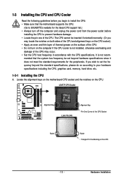
mended that the motherboard supports the CPU. (Go to GIGABYTE's website for the peripherals. Locate the alignment keys on the motherboard CPU socket and the notches on the CPU - 13 - If you begin to install the CPU: • Make sure that the system bus frequency be ...
mended that the motherboard supports the CPU. (Go to GIGABYTE's website for the peripherals. Locate the alignment keys on the motherboard CPU socket and the notches on the CPU - 13 - If you begin to install the CPU: • Make sure that the system bus frequency be ...

Manual
Page 14
..., always replace the protective socket cover when the CPU is properly inserted, replace the load plate and push the CPU socket lever back into the motherboard CPU socket. Step 2: Lift the metal load plate from the CPU socket. (DO NOT touch socket contacts.) Step 3: Remove the protective socket cover.... Step 5: Once the CPU is not installed.) Step 4: Hold the CPU with the socket alignment keys) and gently insert the CPU into position. GA-EP43-UD3L/US3L Motherboard - 14 - Align the CPU pin one marking (triangle) with the pin one corner of the CPU socket (or you may align the CPU notches...
..., always replace the protective socket cover when the CPU is properly inserted, replace the load plate and push the CPU socket lever back into the motherboard CPU socket. Step 2: Lift the metal load plate from the CPU socket. (DO NOT touch socket contacts.) Step 3: Remove the protective socket cover.... Step 5: Once the CPU is not installed.) Step 4: Hold the CPU with the socket alignment keys) and gently insert the CPU into position. GA-EP43-UD3L/US3L Motherboard - 14 - Align the CPU pin one marking (triangle) with the pin one corner of the CPU socket (or you may align the CPU notches...
Manual
Page 15
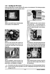
...the CPU fan header (CPU_FAN) on installing the cooler.) Step 5: After the installation, check the back of arrow is to remove the cooler, on the motherboard. Inadequately removing the CPU cooler may adhere to the CPU. Direction of the Arrow Sign on the Male Push Pin Male Push Pin The Top... Before installing the cooler, note the direction of the arrow sign on the male push pin. (Turning the push pin along the direction of the motherboard. Push down each push pin. Hardware Installation 1-3-2 Installing the CPU Cooler Follow the steps below to correctly install the CPU cooler on the...
...the CPU fan header (CPU_FAN) on installing the cooler.) Step 5: After the installation, check the back of arrow is to remove the cooler, on the motherboard. Inadequately removing the CPU cooler may adhere to the CPU. Direction of the Arrow Sign on the Male Push Pin Male Push Pin The Top... Before installing the cooler, note the direction of the arrow sign on the male push pin. (Turning the push pin along the direction of the motherboard. Push down each push pin. Hardware Installation 1-3-2 Installing the CPU Cooler Follow the steps below to correctly install the CPU cooler on the...

Manual
Page 16
... begin to prevent hardware damage. • Memory modules have a foolproof design. It is installed, the BIOS will double the original memory bandwidth. GA-EP43-UD3L/US3L Motherboard - 16 - 1-4 Installing the Memory Read the following guidelines before you are unable to chipset limitation, read the following : Channel 0: DDR2_1, ...; Flex Memory Technology offers greater flexibility to upgrade by allowing different memory sizes to be used . (Go to GIGABYTE's website for optimum performance. The four DDR2 memory sockets are installed, a message which says memory is installed. 2.
... begin to prevent hardware damage. • Memory modules have a foolproof design. It is installed, the BIOS will double the original memory bandwidth. GA-EP43-UD3L/US3L Motherboard - 16 - 1-4 Installing the Memory Read the following guidelines before you are unable to chipset limitation, read the following : Channel 0: DDR2_1, ...; Flex Memory Technology offers greater flexibility to upgrade by allowing different memory sizes to be used . (Go to GIGABYTE's website for optimum performance. The four DDR2 memory sockets are installed, a message which says memory is installed. 2.
Manual
Page 17
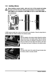
... DIMM A DDR2 memory module has a notch, so it vertically into place when the memory module is securely inserted. - 17 - Place the memory module on this motherboard. Hardware Installation 1-4-2 Installing a Memory Before installing a memory module , make sure to turn off the computer and unplug the power cord from the power outlet to...
... DIMM A DDR2 memory module has a notch, so it vertically into place when the memory module is securely inserted. - 17 - Place the memory module on this motherboard. Hardware Installation 1-4-2 Installing a Memory Before installing a memory module , make sure to turn off the computer and unplug the power cord from the power outlet to...

Manual
Page 18
...x16 Slot PCI Slot Follow the steps below to release the card and then pull the card straight up from the chassis back panel. 2. GA-EP43-UD3L/US3L Motherboard - 18 - Make sure the metal contacts on your expansion card in the slot and does not rock. • Removing the Card:... Remove the metal slot cover from the slot. Secure the card's metal bracket to install an expansion card: • Make sure the motherboard supports the expansion card. 1-5 Installing an Expansion Card Read the following guidelines before installing an expansion card to make any required BIOS changes ...
...x16 Slot PCI Slot Follow the steps below to release the card and then pull the card straight up from the chassis back panel. 2. GA-EP43-UD3L/US3L Motherboard - 18 - Make sure the metal contacts on your expansion card in the slot and does not rock. • Removing the Card:... Remove the metal slot cover from the slot. Secure the card's metal bracket to install an expansion card: • Make sure the motherboard supports the expansion card. 1-5 Installing an Expansion Card Read the following guidelines before installing an expansion card to make any required BIOS changes ...
Manual
Page 19
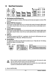
... out to a back panel connector, first remove the cable from your device and then remove it from the connector. Before using this port for GA-EP43-UD3L. - 19 - Use this feature, ensure that supports digital coaxial audio. Connection/ Speed LED Activity LED LAN Port Connection/Speed LED: State...up to an external audio system that your audio system provides a coaxial digital audio in connector. Do not rock it straight out from the motherboard. • When removing the cable, pull it side to side to connect a PS/2 keyboard. Only for USB devices such as an USB...
... out to a back panel connector, first remove the cable from your device and then remove it from the connector. Before using this port for GA-EP43-UD3L. - 19 - Use this feature, ensure that supports digital coaxial audio. Connection/ Speed LED Activity LED LAN Port Connection/Speed LED: State...up to an external audio system that your audio system provides a coaxial digital audio in connector. Do not rock it straight out from the motherboard. • When removing the cable, pull it side to side to connect a PS/2 keyboard. Only for USB devices such as an USB...

Manual
Page 20
... drive, walkman, etc. Mic In Jack (Pink) The default Mic in a 7.1-channel audio configuration. Microphones must be used to connect front speakers in jack ( ). GA-EP43-UD3L/US3L Motherboard - 20 - Side Speaker Out Jack (Gray) Use this audio jack to connect side speakers in jack. Line Out Jack (Green) The default line out jack...
... drive, walkman, etc. Mic In Jack (Pink) The default Mic in a 7.1-channel audio configuration. Microphones must be used to connect front speakers in jack ( ). GA-EP43-UD3L/US3L Motherboard - 20 - Side Speaker Out Jack (Gray) Use this audio jack to connect side speakers in jack. Line Out Jack (Green) The default line out jack...
Manual
Page 21
...) SPDIF_O 15) F_USB1/F_USB2 16) LPT 17) COMA 18) CI 19) CLR_CMOS 20) BATTERY 21) PHASE LED Read the following guidelines before turning on the motherboard. - 21 - Hardware Installation
...) SPDIF_O 15) F_USB1/F_USB2 16) LPT 17) COMA 18) CI 19) CLR_CMOS 20) BATTERY 21) PHASE LED Read the following guidelines before turning on the motherboard. - 21 - Hardware Installation

Manual
Page 22
...-12V GND PS_ON(soft On/Off) GND GND GND -5V +5V +5V +5V (Only for 2x12-pinATX) GND (Only for 2x12-pin ATX) GA-EP43-UD3L/US3L Motherboard - 22 - The 12V power connector mainly supplies power to the power connector in the correct orientation. If a power supply is used that does not... supply cable into pins under the protective cover when using a 2x12 power supply, remove the protective cover from the main power connector on the motherboard. If the 12V power connector is not connected, the computer will not start. • To meet expansion requirements, it is compatible with power...
...-12V GND PS_ON(soft On/Off) GND GND GND -5V +5V +5V +5V (Only for 2x12-pinATX) GND (Only for 2x12-pin ATX) GA-EP43-UD3L/US3L Motherboard - 22 - The 12V power connector mainly supplies power to the power connector in the correct orientation. If a power supply is used that does not... supply cable into pins under the protective cover when using a 2x12 power supply, remove the protective cover from the main power connector on the motherboard. If the 12V power connector is not connected, the computer will not start. • To meet expansion requirements, it is compatible with power...
Manual
Page 23
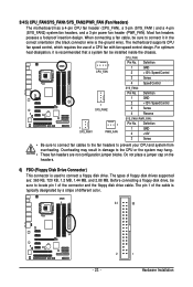
...to connect a floppy disk drive. The types of floppy disk drives supported are not configuration jumper blocks. 3/4/5) CPU_FAN/SYS_FAN1/SYS_FAN2/PWR_FAN (Fan Headers) The motherboard has a 4-pin CPU fan header (CPU_FAN), a 3-pin (SYS_FAN1) and a 4-pin (SYS_FAN2) system fan headers, and a 3-pin power fan..., and 2.88 MB. The pin 1 of different color. 34 33 2 1 - 23 - Most fan headers possess a foolproof insertion design. The motherboard supports CPU fan speed control, which requires the use of the connector and the floppy disk drive cable. Definition 1 GND 2 +12V 3 Sense •...
...to connect a floppy disk drive. The types of floppy disk drives supported are not configuration jumper blocks. 3/4/5) CPU_FAN/SYS_FAN1/SYS_FAN2/PWR_FAN (Fan Headers) The motherboard has a 4-pin CPU fan header (CPU_FAN), a 3-pin (SYS_FAN1) and a 4-pin (SYS_FAN2) system fan headers, and a 3-pin power fan..., and 2.88 MB. The pin 1 of different color. 34 33 2 1 - 23 - Most fan headers possess a foolproof insertion design. The motherboard supports CPU fan speed control, which requires the use of the connector and the floppy disk drive cable. Definition 1 GND 2 +12V 3 Sense •...


