Manual
Page 3
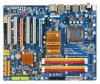
... your motherboard looks like this manual may be made by GIGA-BYTE TECHNOLOGY CO., LTD. All rights reserved. GIGABYTE UNITED INC. Changes to use GIGABYTE's unique features, read the User's Manual. „ For instructions on how to the specifications and features in... information, carefully read or download the information on/from the Support\Motherboard\Technology Guide page on your motherboard revision before updating motherboard BIOS, drivers, or when looking for technical information. No part of the motherboard is exclusively licensed to their respective owners. Example:...
... your motherboard looks like this manual may be made by GIGA-BYTE TECHNOLOGY CO., LTD. All rights reserved. GIGABYTE UNITED INC. Changes to use GIGABYTE's unique features, read the User's Manual. „ For instructions on how to the specifications and features in... information, carefully read or download the information on/from the Support\Motherboard\Technology Guide page on your motherboard revision before updating motherboard BIOS, drivers, or when looking for technical information. No part of the motherboard is exclusively licensed to their respective owners. Example:...
Manual
Page 4
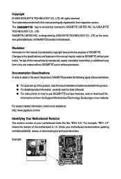
Table of Contents Box Contents ...6 OptionalItems ...6 GA-EP43-DS3R/DS3 Motherboard Layout 7 Block Diagram ...8 Chapter 1 Hardware Installation 9 1-1 Installation Precautions 9 1-2 Product Specifications 10 1-3 Installing the CPU and CPU Cooler ... the SATA Bracket 19 1-7 Back Panel Connectors 20 1-8 Internal Connectors 22 Chapter 2 BIOS Setup 35 2-1 Startup Screen 36 2-2 The Main Menu 37 2-3 MB Intelligent Tweaker(M.I.T 39 2-4 Standard CMOS Features 46 2-5 Advanced BIOS Features 48 2-6 IntegratedPeripherals 51 2-7 Power Management Setup 55 2-8 PnP/PCI Configurations 57 ...
Table of Contents Box Contents ...6 OptionalItems ...6 GA-EP43-DS3R/DS3 Motherboard Layout 7 Block Diagram ...8 Chapter 1 Hardware Installation 9 1-1 Installation Precautions 9 1-2 Product Specifications 10 1-3 Installing the CPU and CPU Cooler ... the SATA Bracket 19 1-7 Back Panel Connectors 20 1-8 Internal Connectors 22 Chapter 2 BIOS Setup 35 2-1 Startup Screen 36 2-2 The Main Menu 37 2-3 MB Intelligent Tweaker(M.I.T 39 2-4 Standard CMOS Features 46 2-5 Advanced BIOS Features 48 2-6 IntegratedPeripherals 51 2-7 Power Management Setup 55 2-8 PnP/PCI Configurations 57 ...
Manual
Page 5
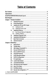
... 3-4 Contact ...67 3-5 System ...67 3-6 Download Center 68 Chapter 4 Unique Features 69 4-1 Xpress Recovery2 69 4-2 BIOS Update Utilities 74 4-2-1 Updating the BIOS with the Q-Flash Utility 74 4-2-2 Updating the BIOS with the @BIOS Utility 77 4-3 EasyTune 6 ...78 4-4 Dynamic Energy Saver Advanced 79 4-5 Ultra TPM (Note 81 4-6 Q-Share ...82...Using the Sound Recorder 104 5-3 Troubleshooting 105 5-3-1 Frequently Asked Questions 105 5-3-2 Troubleshooting Procedure 106 Regulatory Statements 108 Only for GA-EP43-DS3R. (Note) This feature is optional due to different regional policy. - 5 -
... 3-4 Contact ...67 3-5 System ...67 3-6 Download Center 68 Chapter 4 Unique Features 69 4-1 Xpress Recovery2 69 4-2 BIOS Update Utilities 74 4-2-1 Updating the BIOS with the Q-Flash Utility 74 4-2-2 Updating the BIOS with the @BIOS Utility 77 4-3 EasyTune 6 ...78 4-4 Dynamic Energy Saver Advanced 79 4-5 Ultra TPM (Note 81 4-6 Q-Share ...82...Using the Sound Recorder 104 5-3 Troubleshooting 105 5-3-1 Frequently Asked Questions 105 5-3-2 Troubleshooting Procedure 106 Regulatory Statements 108 Only for GA-EP43-DS3R. (Note) This feature is optional due to different regional policy. - 5 -

Manual
Page 8
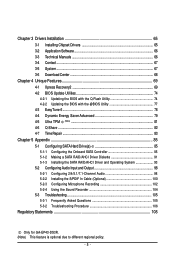
Only for GA-EP43-DS3R. Block Diagram 1 PCI Express x16 1 PCI Express x4 PCIe CLK (100 MHz) PCIe CLK (100 MHz) PCI Express x16 PCI Express x4 1 PCI Express ...® ICH10 Dual BIOS 6 SATA 3Gb/s 12 USB Ports CODEC LPC Bus IT8718 Floppy LPT Port COM Port PS/2 KB/Mouse TPM (Note) Surround Speaker Out Center/Subwoofer Speaker Out Side Speaker Out MIC Line-Out Line-In SPDIF In SPDIF Out 4 PCI PCI CLK (33 MHz) Only for GA-EP43-DS3. (Note) This...
Only for GA-EP43-DS3R. Block Diagram 1 PCI Express x16 1 PCI Express x4 PCIe CLK (100 MHz) PCIe CLK (100 MHz) PCI Express x16 PCI Express x4 1 PCI Express ...® ICH10 Dual BIOS 6 SATA 3Gb/s 12 USB Ports CODEC LPC Bus IT8718 Floppy LPT Port COM Port PS/2 KB/Mouse TPM (Note) Surround Speaker Out Center/Subwoofer Speaker Out Side Speaker Out MIC Line-Out Line-In SPDIF In SPDIF Out 4 PCI PCI CLK (33 MHz) Only for GA-EP43-DS3. (Note) This...
Manual
Page 12
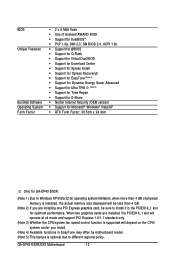
...8 Mbit flash Š Use of licensed AWARD BIOS Š Support for DualBIOSTM Š PnP 1.0a, DMI 2.0, SM BIOS 2.4, ACPI 1.0b Š Support for @BIOS Š Support for Q-Flash Š Support for Virtual Dual BIOS Š Support for Download Center Š Support...supported will depend on the CPU/ system cooler you install. (Note 4) Available functions in the PCIEX16_1 slot for GA-EP43-DS3R. (Note 1) Due to Windows XP/Vista 32-bit operating system limitation, when more than 4 GB. ... memory size displayed will be sure to different regional policy. GA-EP43-DS3R/DS3 Motherboard - 12 -
...8 Mbit flash Š Use of licensed AWARD BIOS Š Support for DualBIOSTM Š PnP 1.0a, DMI 2.0, SM BIOS 2.4, ACPI 1.0b Š Support for @BIOS Š Support for Q-Flash Š Support for Virtual Dual BIOS Š Support for Download Center Š Support...supported will depend on the CPU/ system cooler you install. (Note 4) Available functions in the PCIEX16_1 slot for GA-EP43-DS3R. (Note 1) Due to Windows XP/Vista 32-bit operating system limitation, when more than 4 GB. ... memory size displayed will be sure to different regional policy. GA-EP43-DS3R/DS3 Motherboard - 12 -
Manual
Page 16
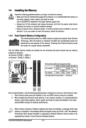
...memory support list.) • Always turn off the computer and unplug the power cord from the power outlet before installing the memory to GIGABYTE's website for optimum performance. DS/SS - - - - Dual Channel mode cannot be used . (Go to prevent hardware damage. ... Dual Channel Memory Configuration This motherboard provides four DDR2 memory sockets and supports Dual Channel Technology. GA-EP43-DS3R/DS3 Motherboard - 16 - After the memory is installed, the BIOS will automatically detect the specifications and capacity of different capacity and chips are installed, a message which...
...memory support list.) • Always turn off the computer and unplug the power cord from the power outlet before installing the memory to GIGABYTE's website for optimum performance. DS/SS - - - - Dual Channel mode cannot be used . (Go to prevent hardware damage. ... Dual Channel Memory Configuration This motherboard provides four DDR2 memory sockets and supports Dual Channel Technology. GA-EP43-DS3R/DS3 Motherboard - 16 - After the memory is installed, the BIOS will automatically detect the specifications and capacity of different capacity and chips are installed, a message which...
Manual
Page 18
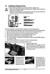
... expansion card. PCI Express x1 Slot PCI Express x16 Slot PCI Express x4 Slot PCI Slot Follow the steps below to make any required BIOS changes for your expansion card in your card. Make sure the card is fully inserted into the slot. 4. 1-5 Installing an Expansion Card...5. After installing all expansion cards, replace the chassis cover(s). 6. Remove the metal slot cover from the slot. Align the card with your computer. GA-EP43-DS3R/DS3 Motherboard - 18 - • Removing the Card from the power outlet before you begin to release the card and then pull the card straight up ...
... expansion card. PCI Express x1 Slot PCI Express x16 Slot PCI Express x4 Slot PCI Slot Follow the steps below to make any required BIOS changes for your expansion card in your card. Make sure the card is fully inserted into the slot. 4. 1-5 Installing an Expansion Card...5. After installing all expansion cards, replace the chassis cover(s). 6. Remove the metal slot cover from the slot. Align the card with your computer. GA-EP43-DS3R/DS3 Motherboard - 18 - • Removing the Card from the power outlet before you begin to release the card and then pull the card straight up ...

Manual
Page 27
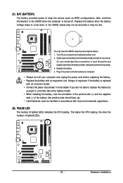
Note the positive and negative pins before connecting the cables. The LED is on when the hard drive is detected, the BIOS may issue beeps in S3/S4/S5 Off S3/S4 sleep state or powered off (S5). • PW (Power Switch, Red): Connects to..."Troubleshooting," for more information). • SPEAK (Speaker, Orange): Connects to indicate the problem. When connecting your system using the power switch (refer to Chapter 2, "BIOS Setup," "Power Management Setup," for information about beep codes. • HD (Hard Drive Activity LED, Blue) Connects to the reset switch on the chassis front...
Note the positive and negative pins before connecting the cables. The LED is on when the hard drive is detected, the BIOS may issue beeps in S3/S4/S5 Off S3/S4 sleep state or powered off (S5). • PW (Power Switch, Red): Connects to..."Troubleshooting," for more information). • SPEAK (Speaker, Orange): Connects to indicate the problem. When connecting your system using the power switch (refer to Chapter 2, "BIOS Setup," "Power Management Setup," for information about beep codes. • HD (Hard Drive Activity LED, Blue) Connects to the reset switch on the chassis front...
Manual
Page 32
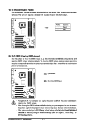
...screwdriver to factory defaults. To clear the CMOS values, place a jumper cap on your computer, be sure to clear the CMOS values (e.g. GA-EP43-DS3R/DS3 Motherboard - 32 - Pin No. 19) CI (Chassis Intrusion Header) This motherboard provides a chassis detection feature that detects if the chassis ...touch the two pins for BIOS configurations). Failure to do so may cause damage to the motherboard. • After system restart, go to BIOS Setup to load factory defaults (select Load Optimized Defaults) or manually configure the BIOS settings (refer to Chapter 2, "BIOS Setup," for a few ...
...screwdriver to factory defaults. To clear the CMOS values, place a jumper cap on your computer, be sure to clear the CMOS values (e.g. GA-EP43-DS3R/DS3 Motherboard - 32 - Pin No. 19) CI (Chassis Intrusion Header) This motherboard provides a chassis detection feature that detects if the chassis ...touch the two pins for BIOS configurations). Failure to do so may cause damage to the motherboard. • After system restart, go to BIOS Setup to load factory defaults (select Load Optimized Defaults) or manually configure the BIOS settings (refer to Chapter 2, "BIOS Setup," for a few ...
Manual
Page 33
... wait for 5 seconds.) 3. Danger of explosion if the battery is turned off. 21) BAT (BATTERY) The battery provides power to keep the values (such as BIOS configurations, date, and time information) in the CMOS when the computer is replaced with an incorrect model. • Contact the place of purchase or local...
... wait for 5 seconds.) 3. Danger of explosion if the battery is turned off. 21) BAT (BATTERY) The battery provides power to keep the values (such as BIOS configurations, date, and time information) in the CMOS when the computer is replaced with an incorrect model. • Contact the place of purchase or local...
Manual
Page 35
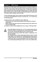
... turned on the motherboard supplies the necessary power to the CMOS to clear the CMOS values.) - 35 - To see more advanced BIOS Setup menu options, you not flash the BIOS. To upgrade the BIOS, use either the GIGABYTE Q-Flash or @BIOS utility. • Q-Flash allows the user to quickly and easily upgrade or back up...
... turned on the motherboard supplies the necessary power to the CMOS to clear the CMOS values.) - 35 - To see more advanced BIOS Setup menu options, you not flash the BIOS. To upgrade the BIOS, use either the GIGABYTE Q-Flash or @BIOS utility. • Q-Flash allows the user to quickly and easily upgrade or back up...

Manual
Page 36
...first boot device setting as needed. : Q-Flash Press the key to access the Q-Flash utility directly without entering BIOS Setup. To exit Boot Menu, press . Motherboard Model BIOS Version EP43-DS3R D2 . . . . The system will still be used for one time only. Note: The setting... the instructions on the Full Screen LOGO Show item on BIOS Setup settings. The POST Screen Award Modular BIOS v6.00PG, An Energy Star Ally Copyright (C) 1984-2008, Award Software, Inc. GA-EP43-DS3R/DS3 Motherboard - 36 - A. Function Keys: : BIOS Setup : XpressRecovery2 : Boot Menu : Qflash 04/16/...
...first boot device setting as needed. : Q-Flash Press the key to access the Q-Flash utility directly without entering BIOS Setup. To exit Boot Menu, press . Motherboard Model BIOS Version EP43-DS3R D2 . . . . The system will still be used for one time only. Note: The setting... the instructions on the Full Screen LOGO Show item on BIOS Setup settings. The POST Screen Award Modular BIOS v6.00PG, An Energy Star Ally Copyright (C) 1984-2008, Award Software, Inc. GA-EP43-DS3R/DS3 Motherboard - 36 - A. Function Keys: : BIOS Setup : XpressRecovery2 : Boot Menu : Qflash 04/16/...
Manual
Page 37
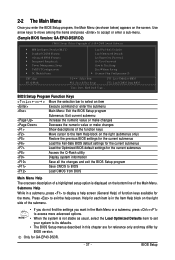
...Load Optimized Defaults item to set your system to its defaults. • The BIOS Setup menus described in this chapter are for reference only and may differ by BIOS version. Only for GA-EP43-DS3R. - 37 - BIOS Setup Use arrow keys to move among the items and press to accept or ...enter a sub-menu. (Sample BIOS Version: GA-EP43-DS3R D2) CMOS Setup Utility-Copyright (C) 1984-2008 Award Software ...
...Load Optimized Defaults item to set your system to its defaults. • The BIOS Setup menus described in this chapter are for reference only and may differ by BIOS version. Only for GA-EP43-DS3R. - 37 - BIOS Setup Use arrow keys to move among the items and press to accept or ...enter a sub-menu. (Sample BIOS Version: GA-EP43-DS3R D2) CMOS Setup Utility-Copyright (C) 1984-2008 Award Software ...

Manual
Page 38
...menu to 8 profiles (Profile 1-8) and name each profile. Pressing to the confirmation message will exit BIOS Setup. (Pressing can create up to configure the TPM function. GA-EP43-DS3R/DS3 Motherboard - 38 - You can also carry out this task.) „ Security Chip Configuration Use ...are factory settings for the most stable, minimal-performance system operations. „ Load Optimized Defaults Optimized defaults are factory settings for GA-EP43-DS3R. Only for optimal-performance system operations. „ Set Supervisor Password Change, set , or disable password. It allows you...
...menu to 8 profiles (Profile 1-8) and name each profile. Pressing to the confirmation message will exit BIOS Setup. (Pressing can create up to configure the TPM function. GA-EP43-DS3R/DS3 Motherboard - 38 - You can also carry out this task.) „ Security Chip Configuration Use ...are factory settings for the most stable, minimal-performance system operations. „ Load Optimized Defaults Optimized defaults are factory settings for GA-EP43-DS3R. Only for optimal-performance system operations. „ Set Supervisor Password Change, set , or disable password. It allows you...
Manual
Page 39
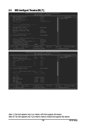
BIOS Setup 2-3 MB Intelligent Tweaker(M.I.T.) CMOS Setup Utility-Copyright (C) 1984-2008 Award Software MB Intelligent Tweaker(M.I.T.) Robust Graphics Booster CPU Clock Ratio (Note 1) Fine CPU Clock ...
BIOS Setup 2-3 MB Intelligent Tweaker(M.I.T.) CMOS Setup Utility-Copyright (C) 1984-2008 Award Software MB Intelligent Tweaker(M.I.T.) Robust Graphics Booster CPU Clock Ratio (Note 1) Fine CPU Clock ...

Manual
Page 40
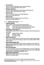
...: Disabled) (Note) This item appears only if you to automatically set in the CPU Clock Ratio item above by 0.5. Auto allows the BIOS to increase the CPU clock ratio set the R.G.B. Options are: Auto (default), Fast, Turbo. CPU Frequency Displays the current operating CPU frequency....) Robust Graphics Booster Robust Graphics Booster (R.G.B.) helps to CPU, chipset, or memory and reduce the useful life of these components. GA-EP43-DS3R/DS3 Motherboard - 40 - Incorrectly doing overclock/overvoltage may result in damage to enhance the performance of CPU host clock. mode based on...
...: Disabled) (Note) This item appears only if you to automatically set in the CPU Clock Ratio item above by 0.5. Auto allows the BIOS to increase the CPU clock ratio set the R.G.B. Options are: Auto (default), Fast, Turbo. CPU Frequency Displays the current operating CPU frequency....) Robust Graphics Booster Robust Graphics Booster (R.G.B.) helps to CPU, chipset, or memory and reduce the useful life of these components. GA-EP43-DS3R/DS3 Motherboard - 40 - Incorrectly doing overclock/overvoltage may result in damage to enhance the performance of CPU host clock. mode based on...

Manual
Page 41
... to manually set the CPU host frequency. The adjustable range is highly dependent on CPU loading. Disabled Disables the use of your system hardware components. BIOS Setup This item is configurable only if the CPU Host Clock Control option is from 90 MHz to 150 MHz. For a 1066 MHz FSB CPU...
... to manually set the CPU host frequency. The adjustable range is highly dependent on CPU loading. Disabled Disables the use of your system hardware components. BIOS Setup This item is configurable only if the CPU Host Clock Control option is from 90 MHz to 150 MHz. For a 1066 MHz FSB CPU...
Manual
Page 42
...Express and North Bridge clock. Lets the system operate at its good performance level. (Default) Lets the system operate at three different performance levels. GA-EP43-DS3R/DS3 Motherboard - 42 - Options are : Auto (default), 200MHz, 266MHz, 333MHz, 400MHz. Options are: 0ps~750ps. (Default: 0ps) ******** ...first memory frequency value is the normal operating frequency of the CPU and North Bridge clock. Extreme Memory Profile (X.M.P.) (Note) Allows the BIOS to read the SPD data on CPU FSB and the (G)MCH Frequency Latch settings. Options are : 700mV, 800mV, 900mV (default), ...
...Express and North Bridge clock. Lets the system operate at its good performance level. (Default) Lets the system operate at three different performance levels. GA-EP43-DS3R/DS3 Motherboard - 42 - Options are : Auto (default), 200MHz, 266MHz, 333MHz, 400MHz. Options are: 0ps~750ps. (Default: 0ps) ******** ...first memory frequency value is the normal operating frequency of the CPU and North Bridge clock. Extreme Memory Profile (X.M.P.) (Note) Allows the BIOS to read the SPD data on CPU FSB and the (G)MCH Frequency Latch settings. Options are : 700mV, 800mV, 900mV (default), ...
Manual
Page 43
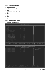
tRP Options are : Auto (default), 1~15. tRCD Options are : Auto (default), 1~15. tRAS Options are : Auto (default), 3~7. ESC: Exit F1: General Help F7: Optimized Defaults BIOS Setup >>>>> Standard Timing Control CAS Latency Time Options are : Auto (default), 1~63. >>>>> Advanced Timing Control Advanced Timing Control CMOS Setup Utility-Copyright (C) 1984-2008 Award ...
tRP Options are : Auto (default), 1~15. tRCD Options are : Auto (default), 1~15. tRAS Options are : Auto (default), 3~7. ESC: Exit F1: General Help F7: Optimized Defaults BIOS Setup >>>>> Standard Timing Control CAS Latency Time Options are : Auto (default), 1~63. >>>>> Advanced Timing Control Advanced Timing Control CMOS Setup Utility-Copyright (C) 1984-2008 Award ...
Manual
Page 45
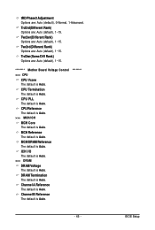
... Auto. ICH I/O The default is Auto. >>> DRAM DRAM Voltage The default is Auto. MCH Reference The default is Auto. Channel B Reference The default is Auto. BIOS Setup Twr2rd(Different Rank) Options are : Auto (default), 1~15. CPU PLL The default is Auto. ******** - 45 - DRAM Termination The default is Auto. CPU Reference The...
... Auto. ICH I/O The default is Auto. >>> DRAM DRAM Voltage The default is Auto. MCH Reference The default is Auto. Channel B Reference The default is Auto. BIOS Setup Twr2rd(Different Rank) Options are : Auto (default), 1~15. CPU PLL The default is Auto. ******** - 45 - DRAM Termination The default is Auto. CPU Reference The...


