Manual
Page 1
GA-EP43-DS3R/ GA-EP43-DS3 LGA775 socket motherboard for Intel® CoreTM processor family/ Intel® Pentium® processor family/Intel® Celeron® processor family User's Manual Rev. 1004 12ME-EP43DS3R-1004R
GA-EP43-DS3R/ GA-EP43-DS3 LGA775 socket motherboard for Intel® CoreTM processor family/ Intel® Pentium® processor family/Intel® Celeron® processor family User's Manual Rev. 1004 12ME-EP43DS3R-1004R
Manual
Page 2
Motherboard GA-EP43-DS3R/GA-EP43-DS3 May 15, 2008 Motherboard GA-EP43-DS3R/ GA-EP43-DS3 May 15, 2008
Motherboard GA-EP43-DS3R/GA-EP43-DS3 May 15, 2008 Motherboard GA-EP43-DS3R/ GA-EP43-DS3 May 15, 2008
Manual
Page 4
Table of Contents Box Contents ...6 OptionalItems ...6 GA-EP43-DS3R/DS3 Motherboard Layout 7 Block Diagram ...8 Chapter 1 Hardware Installation 9 1-1 Installation Precautions 9 1-2 Product Specifications 10 1-3 Installing the CPU and CPU Cooler 13 1-3-1 Installing the CPU 13 1-3-2 Installing the ... 60 2-12 Set Supervisor/User Password 61 2-13 Save & Exit Setup 62 2-14 Exit Without Saving 62 2-15 Security Chip Configuration (Note 63 Only for GA-EP43-DS3R. - 4 -
Table of Contents Box Contents ...6 OptionalItems ...6 GA-EP43-DS3R/DS3 Motherboard Layout 7 Block Diagram ...8 Chapter 1 Hardware Installation 9 1-1 Installation Precautions 9 1-2 Product Specifications 10 1-3 Installing the CPU and CPU Cooler 13 1-3-1 Installing the CPU 13 1-3-2 Installing the ... 60 2-12 Set Supervisor/User Password 61 2-13 Save & Exit Setup 62 2-14 Exit Without Saving 62 2-15 Security Chip Configuration (Note 63 Only for GA-EP43-DS3R. - 4 -
Manual
Page 6
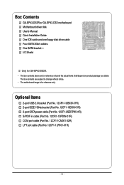
The box contents are for reference only. Box Contents GA-EP43-DS3R or GA-EP43-DS3 motherboard Motherboard driver disk User's Manual Quick Installation Guide One IDE cable and one floppy disk drive cable Four SATA 3Gb/s cables One SATA bracket I/O Shield Only for GA-EP43-DS3R. • The box contents above are subject to change without notice...
The box contents are for reference only. Box Contents GA-EP43-DS3R or GA-EP43-DS3 motherboard Motherboard driver disk User's Manual Quick Installation Guide One IDE cable and one floppy disk drive cable Four SATA 3Gb/s cables One SATA bracket I/O Shield Only for GA-EP43-DS3R. • The box contents above are subject to change without notice...
Manual
Page 7
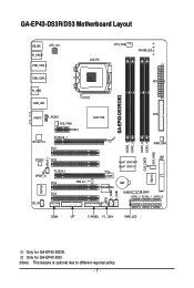
... Layout KB_MS ATX_12V R_SPDIF USB_1394_2 LGA775 CPU_FAN PHASE LED USB_1394_1 ATX R_USB GA-EP43-DS3R/DS3 USB_LAN AUDIO F_AUDIO SYS_FAN1 PCIEX1 RTL8111C PCIEX16_1 PCI1 Intel® P43 FDD PWR_FAN DDR2_3 CLR_CMOS DDR2_4 SYS_FAN2 DDR2_1 DDR2_2 SPDIF_I CODEC PCI2 SPDIF_O PCIEX4_1 PCI3 ...; ICH10 IT8213 TPM IC (Note) TSB43AB23 CI F_USB2 F_USB1 BAT M_BIOS B_BIOS SATA2_4 SATA2_2 SATA2_0 SATA2_5 SATA2_3 SATA2_1 COMA LPT F_PANEL F1_1394 PWR_LED Only for GA-EP43-DS3. (Note) This feature is optional due to different regional policy. - 7 - Only for...
... Layout KB_MS ATX_12V R_SPDIF USB_1394_2 LGA775 CPU_FAN PHASE LED USB_1394_1 ATX R_USB GA-EP43-DS3R/DS3 USB_LAN AUDIO F_AUDIO SYS_FAN1 PCIEX1 RTL8111C PCIEX16_1 PCI1 Intel® P43 FDD PWR_FAN DDR2_3 CLR_CMOS DDR2_4 SYS_FAN2 DDR2_1 DDR2_2 SPDIF_I CODEC PCI2 SPDIF_O PCIEX4_1 PCI3 ...; ICH10 IT8213 TPM IC (Note) TSB43AB23 CI F_USB2 F_USB1 BAT M_BIOS B_BIOS SATA2_4 SATA2_2 SATA2_0 SATA2_5 SATA2_3 SATA2_1 COMA LPT F_PANEL F1_1394 PWR_LED Only for GA-EP43-DS3. (Note) This feature is optional due to different regional policy. - 7 - Only for...

Manual
Page 8
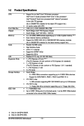
... Speaker Out Center/Subwoofer Speaker Out Side Speaker Out MIC Line-Out Line-In SPDIF In SPDIF Out 4 PCI PCI CLK (33 MHz) Only for GA-EP43-DS3. (Note) This feature is optional due to different regional policy. - 8 - Only for...
... Speaker Out Center/Subwoofer Speaker Out Side Speaker Out MIC Line-Out Line-In SPDIF In SPDIF Out 4 PCI PCI CLK (33 MHz) Only for GA-EP43-DS3. (Note) This feature is optional due to different regional policy. - 8 - Only for...
Manual
Page 10
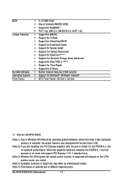
...; Up to 3 IEEE 1394a ports (2 on the back panel, 1 via the IEEE 1394a bracket connected to the internal IEEE 1394a header) Only for GA-EP43-DS3. Only for GA-EP43-DS3R. Support for CD In Š Realtek 8111C chip (10/100/1000 Mbit) Š 1 x PCI Express x16 slot (Note 2) (The PCI...16 GB of system memory (Note 1) Š Dual channel memory architecture Š Support for DDR2 1200 (O.C.)/1066/800/667 MHz memory modules (Go to GIGABYTE's website for the latest memory support list.) Š Realtek ALC888 codec Š High Definition Audio Š 2/4/5.1/7.1-channel Š Support for S/PDIF In/...
...; Up to 3 IEEE 1394a ports (2 on the back panel, 1 via the IEEE 1394a bracket connected to the internal IEEE 1394a header) Only for GA-EP43-DS3. Only for GA-EP43-DS3R. Support for CD In Š Realtek 8111C chip (10/100/1000 Mbit) Š 1 x PCI Express x16 slot (Note 2) (The PCI...16 GB of system memory (Note 1) Š Dual channel memory architecture Š Support for DDR2 1200 (O.C.)/1066/800/667 MHz memory modules (Go to GIGABYTE's website for the latest memory support list.) Š Realtek ALC888 codec Š High Definition Audio Š 2/4/5.1/7.1-channel Š Support for S/PDIF In/...
Manual
Page 12
... Security (OEM version) Š Support for Microsoft® Windows® Vista/XP Š ATX Form Factor; 30.5cm x 24.4cm Only for optimum performance. GA-EP43-DS3R/DS3 Motherboard - 12 - When two graphics cards are installed, the PCIEX16_1 slot will operate at x4 mode and support PCI Express 1.0/1.1 standard only. (Note 3) Whether the...
... Security (OEM version) Š Support for Microsoft® Windows® Vista/XP Š ATX Form Factor; 30.5cm x 24.4cm Only for optimum performance. GA-EP43-DS3R/DS3 Motherboard - 12 - When two graphics cards are installed, the PCIEX16_1 slot will operate at x4 mode and support PCI Express 1.0/1.1 standard only. (Note 3) Whether the...
Manual
Page 14
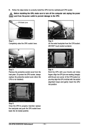
... the power outlet to prevent damage to correctly install the CPU into its locked position. CPU Socket Lever Step 1: Completely raise the CPU socket lever. GA-EP43-DS3R/DS3 Motherboard - 14 - Follow the steps below to the CPU. Align the CPU pin one marking (triangle) with the pin one corner of the CPU...
... the power outlet to prevent damage to correctly install the CPU into its locked position. CPU Socket Lever Step 1: Completely raise the CPU socket lever. GA-EP43-DS3R/DS3 Motherboard - 14 - Follow the steps below to the CPU. Align the CPU pin one marking (triangle) with the pin one corner of the CPU...
Manual
Page 16
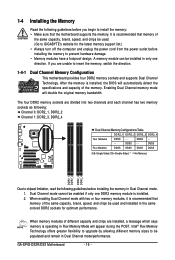
... to install the memory: • Make sure that memory of the same capacity, brand, speed, and chips be used . (Go to GIGABYTE's website for optimum performance. DS/SS - - The four DDR2 memory sockets are installed, a message which says memory is installed, the BIOS... sockets and supports Dual Channel Technology. Dual Channel mode cannot be installed in Dual Channel mode. 1. When memory modules of the memory. GA-EP43-DS3R/DS3 Motherboard - 16 - It is installed. 2. 1-4 Installing the Memory Read the following guidelines before you are unable to prevent hardware damage....
... to install the memory: • Make sure that memory of the same capacity, brand, speed, and chips be used . (Go to GIGABYTE's website for optimum performance. DS/SS - - The four DDR2 memory sockets are installed, a message which says memory is installed, the BIOS... sockets and supports Dual Channel Technology. Dual Channel mode cannot be installed in Dual Channel mode. 1. When memory modules of the memory. GA-EP43-DS3R/DS3 Motherboard - 16 - It is installed. 2. 1-4 Installing the Memory Read the following guidelines before you are unable to prevent hardware damage....
Manual
Page 18
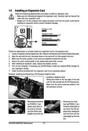
... the end of the card until it is fully seated in the slot. 3. If necessary, go to BIOS Setup to correctly install your expansion card(s). 7. GA-EP43-DS3R/DS3 Motherboard - 18 - • Removing the Card from the PCIEX16_1 slot: Gently push back on the lever on the card are completely inserted into the...
... the end of the card until it is fully seated in the slot. 3. If necessary, go to BIOS Setup to correctly install your expansion card(s). 7. GA-EP43-DS3R/DS3 Motherboard - 18 - • Removing the Card from the PCIEX16_1 slot: Gently push back on the lever on the card are completely inserted into the...
Manual
Page 20
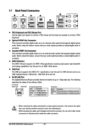
GA-EP43-DS3R/DS3 Motherboard - 20 - 1-7 Back Panel Connectors PS/2 Keyboard and PS/2 Mouse Port Use the upper port (green) to connect a PS/2 mouse and the lower port (purple) ...
GA-EP43-DS3R/DS3 Motherboard - 20 - 1-7 Back Panel Connectors PS/2 Keyboard and PS/2 Mouse Port Use the upper port (green) to connect a PS/2 mouse and the lower port (purple) ...
Manual
Page 22
GA-EP43-DS3R/DS3 Motherboard - 22 - Unplug the power cord from the power outlet to prevent damage to the devices. • After installing the device and before connecting external ...
GA-EP43-DS3R/DS3 Motherboard - 22 - Unplug the power cord from the power outlet to prevent damage to the devices. • After installing the device and before connecting external ...
Manual
Page 24
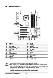
... supports CPU fan speed control, which requires the use of the connector and the floppy disk drive cable. The pin 1 of different color. 34 33 GA-EP43-DS3R/DS3 Motherboard 2 1 - 24 - Most fan headers possess a foolproof insertion design. Definition 1 GND 2 +12V 3 Sense 4 Speed Control SYS_FAN2: Pin No. For optimum heat dissipation, it in...
... supports CPU fan speed control, which requires the use of the connector and the floppy disk drive cable. The pin 1 of different color. 34 33 GA-EP43-DS3R/DS3 Motherboard 2 1 - 24 - Most fan headers possess a foolproof insertion design. Definition 1 GND 2 +12V 3 Sense 4 Speed Control SYS_FAN2: Pin No. For optimum heat dissipation, it in...

Manual
Page 25
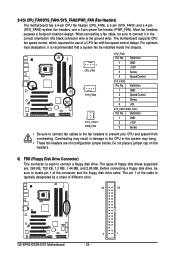
... SATA hard drive. Please connect the L-shaped end of the IDE devices (for example, master or slave). (For information about configuring master/slave settings for GA-EP43-DS3. - 25 - SATA2_4 7 1 SATA2_5 SATA2_2 SATA2_3 SATA2_0 1 7 SATA2_1 Pin No. 1 2 3 4 5 6 7 Definition GND TXP TXN GND RXN RXP GND Only for the IDE devices, read the instructions...
... SATA hard drive. Please connect the L-shaped end of the IDE devices (for example, master or slave). (For information about configuring master/slave settings for GA-EP43-DS3. - 25 - SATA2_4 7 1 SATA2_5 SATA2_2 SATA2_3 SATA2_0 1 7 SATA2_1 Pin No. 1 2 3 4 5 6 7 Definition GND TXP TXN GND RXN RXP GND Only for the IDE devices, read the instructions...
Manual
Page 26
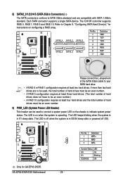
The LED keeps blinking when the system is in S3/S4 sleep state or powered off when the system is in S1 sleep state. GA-EP43-DS3R/DS3 Motherboard - 26 - System Status LED S0 On S1 Blinking S3/S4/S5 Off The LED is operating. The LED is off (S5). 1 ... two hard drives are compatible with SATA 1.5Gb/s standard. Pin No. 1 2 3 Definition MPD+ MPDMPD- Refer to Chapter 5, "Configuring SATA Hard Drive(s)," for GA-EP43-DS3R. 8) SATA2_0/1/2/3/4/5 (SATA 3Gb/s Connectors) The SATA connectors conform to SATA 3Gb/s standard and are to be used, the total number of hard drives does...
The LED keeps blinking when the system is in S3/S4 sleep state or powered off when the system is in S1 sleep state. GA-EP43-DS3R/DS3 Motherboard - 26 - System Status LED S0 On S1 Blinking S3/S4/S5 Off The LED is operating. The LED is off (S5). 1 ... two hard drives are compatible with SATA 1.5Gb/s standard. Pin No. 1 2 3 Definition MPD+ MPDMPD- Refer to Chapter 5, "Configuring SATA Hard Drive(s)," for GA-EP43-DS3R. 8) SATA2_0/1/2/3/4/5 (SATA 3Gb/s Connectors) The SATA connectors conform to SATA 3Gb/s standard and are to be used, the total number of hard drives does...
Manual
Page 28
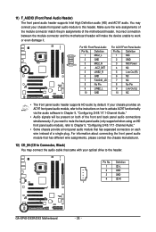
... HD audio by default. Pin No. For HD Front Panel Audio: For AC'97 Front Panel Audio: Pin No. Definition 1 CD-L 2 GND 3 GND 4 CD-R 1 GA-EP43-DS3R/DS3 Motherboard - 28 - Definition Pin No. You may connect the audio cable that came with your optical drive to the header. If your chassis front panel...
... HD audio by default. Pin No. For HD Front Panel Audio: For AC'97 Front Panel Audio: Pin No. Definition 1 CD-L 2 GND 3 GND 4 CD-R 1 GA-EP43-DS3R/DS3 Motherboard - 28 - Definition Pin No. You may connect the audio cable that came with your optical drive to the header. If your chassis front panel...
Manual
Page 30
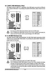
... prevent damage to the USB bracket. 16) F1_1394 (IEEE 1394a Header, Gray) The header conforms to USB 2.0/1.1 specification. Ensure that the cable is securely connected. GA-EP43-DS3R/DS3 Motherboard - 30 - 15) F_USB1/F_USB2 (USB Headers, Yellow) The headers conform to IEEE 1394a specification. For purchasing the optional IEEE 1394a bracket, please contact...
... prevent damage to the USB bracket. 16) F1_1394 (IEEE 1394a Header, Gray) The header conforms to USB 2.0/1.1 specification. Ensure that the cable is securely connected. GA-EP43-DS3R/DS3 Motherboard - 30 - 15) F_USB1/F_USB2 (USB Headers, Yellow) The headers conform to IEEE 1394a specification. For purchasing the optional IEEE 1394a bracket, please contact...
Manual
Page 32
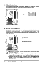
To clear the CMOS values, place a jumper cap on your computer, be sure to remove the jumper cap from the jumper. GA-EP43-DS3R/DS3 Motherboard - 32 - Definition 1 1 Signal 2 GND 20) CLR_CMOS (Clearing CMOS Jumper) Use this jumper to touch the two pins for BIOS configurations). Pin No. date information ...
To clear the CMOS values, place a jumper cap on your computer, be sure to remove the jumper cap from the jumper. GA-EP43-DS3R/DS3 Motherboard - 32 - Definition 1 1 Signal 2 GND 20) CLR_CMOS (Clearing CMOS Jumper) Use this jumper to touch the two pins for BIOS configurations). Pin No. date information ...
Manual
Page 34
GA-EP43-DS3R/DS3 Motherboard - 34 -
GA-EP43-DS3R/DS3 Motherboard - 34 -


