Manual
Page 1
GA-EP35-DS3R/ GA-EP35-DS3 LGA775 socket motherboard for Intel® CoreTM processor family/ Intel® Pentium® processor family/Intel® Celeron® processor family User's Manual Rev. 2101 12ME-EP35DS3R-2101R
GA-EP35-DS3R/ GA-EP35-DS3 LGA775 socket motherboard for Intel® CoreTM processor family/ Intel® Pentium® processor family/Intel® Celeron® processor family User's Manual Rev. 2101 12ME-EP35DS3R-2101R
Manual
Page 2
Motherboard GA-EP35-DS3R/DS3 Dec. 21, 2007 Motherboard GA-EP35-DS3R/DS3 Dec. 21, 2007
Motherboard GA-EP35-DS3R/DS3 Dec. 21, 2007 Motherboard GA-EP35-DS3R/DS3 Dec. 21, 2007
Manual
Page 3
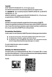
...-BYTE TECHNOLOGY CO., LTD as the exclu- For product-related information, check on our website at: http://www.gigabyte.com.tw Identifying Your Motherboard Revision The revision number on our website. The logo is 1.0. No part of this manual may be reproduced, copied..., transmitted, or published in this manual are legally registered to GIGABYTE UNITED INC. Check your motherboard looks like this product, GIGABYTE provides the following types of documentations: „ For quick set-up of GIGABYTE. by any means without prior notice. Documentation Classifications In order...
...-BYTE TECHNOLOGY CO., LTD as the exclu- For product-related information, check on our website at: http://www.gigabyte.com.tw Identifying Your Motherboard Revision The revision number on our website. The logo is 1.0. No part of this manual may be reproduced, copied..., transmitted, or published in this manual are legally registered to GIGABYTE UNITED INC. Check your motherboard looks like this product, GIGABYTE provides the following types of documentations: „ For quick set-up of GIGABYTE. by any means without prior notice. Documentation Classifications In order...

Manual
Page 4
Table of Contents Box Contents ...6 OptionalItems ...6 GA-EP35-DS3R/DS3 Motherboard Layout 7 Block Diagram ...8 Chapter 1 Hardware Installation 9 1-1 Installation Precautions 9 1-2 Product Specifications 10 1-3 Installing the CPU and CPU Cooler 13 1-3-1 Installing the CPU 13 1-3-2 Installing the CPU ...
Table of Contents Box Contents ...6 OptionalItems ...6 GA-EP35-DS3R/DS3 Motherboard Layout 7 Block Diagram ...8 Chapter 1 Hardware Installation 9 1-1 Installation Precautions 9 1-2 Product Specifications 10 1-3 Installing the CPU and CPU Cooler 13 1-3-1 Installing the CPU 13 1-3-2 Installing the CPU ...
Manual
Page 6
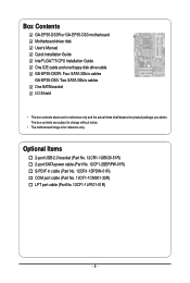
...12CF1-1CM001-32R) LPT port cable (Part No. 12CF1-1LP001-01R) - 6 - The box contents are for reference only. Box Contents GA-EP35-DS3R or GA-EP35-DS3 motherboard Motherboard driver disk User's Manual Quick Installation Guide Intel® LGA775 CPU Installation Guide One IDE cable and one floppy disk drive cable... GA-EP35-DS3R: Four SATA 3Gb/s cables GA-EP35-DS3: Two SATA 3Gb/s cables One SATA bracket I/O Shield • The box contents above are subject to change without notice. • The motherboard image is for reference only and the actual ...
...12CF1-1CM001-32R) LPT port cable (Part No. 12CF1-1LP001-01R) - 6 - The box contents are for reference only. Box Contents GA-EP35-DS3R or GA-EP35-DS3 motherboard Motherboard driver disk User's Manual Quick Installation Guide Intel® LGA775 CPU Installation Guide One IDE cable and one floppy disk drive cable... GA-EP35-DS3R: Four SATA 3Gb/s cables GA-EP35-DS3: Two SATA 3Gb/s cables One SATA bracket I/O Shield • The box contents above are subject to change without notice. • The motherboard image is for reference only and the actual ...
Manual
Page 7
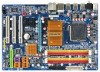
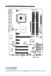
GA-EP35-DS3R/DS3 Motherboard Layout KB_MS RCA_SPDIF R_USB1 R_USB2 R_USB3 ATX_12V LGA775 PHASE LED CPU_FAN ATX GA-EP35-DS3R/DS3 DDRII1 USB_LAN F_AUDIO AUDIO SYS_FAN1 PCIE_3 PCIE_16 RTL8111B PCIE_1 SPDIF_O PCIE_2 CODEC PCI1 SPDIF_I PCI2 IT8718 CD_IN PCI3 COMA Intel® P35 FDD DDRII3 DDRII4 DDRII2 PWR_FAN BATTERY Intel® ICH9R Intel® ICH9 SATAII2 CLR_CMOS SATAII3 GSATAII0 GIGABYTE SATA2 GSATAII1 SATAII0 SATAII1 SATAII4 SATAII5 IDE1 F_USB2 F_USB1 M_BIOS CI F_PANEL LPT B_BIOS PWR_LED SYS_FAN2 Only for GA-EP35-DS3. - 7 - Only for GA-EP35-DS3R.
GA-EP35-DS3R/DS3 Motherboard Layout KB_MS RCA_SPDIF R_USB1 R_USB2 R_USB3 ATX_12V LGA775 PHASE LED CPU_FAN ATX GA-EP35-DS3R/DS3 DDRII1 USB_LAN F_AUDIO AUDIO SYS_FAN1 PCIE_3 PCIE_16 RTL8111B PCIE_1 SPDIF_O PCIE_2 CODEC PCI1 SPDIF_I PCI2 IT8718 CD_IN PCI3 COMA Intel® P35 FDD DDRII3 DDRII4 DDRII2 PWR_FAN BATTERY Intel® ICH9R Intel® ICH9 SATAII2 CLR_CMOS SATAII3 GSATAII0 GIGABYTE SATA2 GSATAII1 SATAII0 SATAII1 SATAII4 SATAII5 IDE1 F_USB2 F_USB1 M_BIOS CI F_PANEL LPT B_BIOS PWR_LED SYS_FAN2 Only for GA-EP35-DS3. - 7 - Only for GA-EP35-DS3R.

Manual
Page 9
... within an electrostatic shielding container. • Before unplugging the power supply cable from the power outlet before installing or removing the motherboard or other hardware components. • When connecting hardware components to the internal connectors on top of the product, please consult a certified computer...an ESD wrist strap, keep your hands dry and first touch a metal object to eliminate static electricity. • Prior to installing the motherboard, please have a problem related to the use of an antistatic pad or within the computer casing. • Do not place the ...
... within an electrostatic shielding container. • Before unplugging the power supply cable from the power outlet before installing or removing the motherboard or other hardware components. • When connecting hardware components to the internal connectors on top of the product, please consult a certified computer...an ESD wrist strap, keep your hands dry and first touch a metal object to eliminate static electricity. • Prior to installing the motherboard, please have a problem related to the use of an antistatic pad or within the computer casing. • Do not place the ...
Manual
Page 10
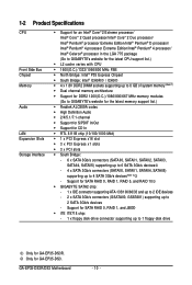
... memory (Note 1) Š Dual channel memory architecture Š Support for DDR2 1200(O.C.)/1066/800/667 MHz memory modules (Go to GIGABYTE's website for the latest memory support list.) Š Realtek ALC889A codec Š High Definition Audio Š 2/4/5.1/7.1-channel Š Support... up to 6 SATA 3Gb/s devices - 4 x SATA 3Gb/s connectors (SATAII0, SATAII1, SATAII4, SATAII5) supporting up to 1 floppy disk drive Only for GA-EP35-DS3R. GA-EP35-DS3R/DS3 Motherboard - 10 - Support for SATA RAID 0, RAID 1, and JBOD Š iTE IT8718 chip: - 1 x floppy disk drive connector supporting up to 2 ...
... memory (Note 1) Š Dual channel memory architecture Š Support for DDR2 1200(O.C.)/1066/800/667 MHz memory modules (Go to GIGABYTE's website for the latest memory support list.) Š Realtek ALC889A codec Š High Definition Audio Š 2/4/5.1/7.1-channel Š Support... up to 6 SATA 3Gb/s devices - 4 x SATA 3Gb/s connectors (SATAII0, SATAII1, SATAII4, SATAII5) supporting up to 1 floppy disk drive Only for GA-EP35-DS3R. GA-EP35-DS3R/DS3 Motherboard - 10 - Support for SATA RAID 0, RAID 1, and JBOD Š iTE IT8718 chip: - 1 x floppy disk drive connector supporting up to 2 ...
Manual
Page 12
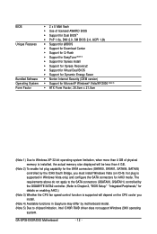
...Energy Saver Š Norton Internet Security (OEM version) Š Support for AHCI mode. GA-EP35-DS3R/DS3 Motherboard - 12 - The requirements above do not apply to the SATA connectors (GSATAII0, GSATAII1) controlled by the GIGABYTE SATA2 controller. (Refer to Chapter 2, "BIOS Setup," "Integrated Peripherals," for details on ...less than 4 GB. (Note 2) To enable hot plug capability for the SATA connectors (SATAII0, SATAII1, SATAII4, SATAII5) controlled by motherboard model. (Note 5) Due to Windows XP 32-bit operating system limitation, when more than 4 GB of physical memory is installed, ...
...Energy Saver Š Norton Internet Security (OEM version) Š Support for AHCI mode. GA-EP35-DS3R/DS3 Motherboard - 12 - The requirements above do not apply to the SATA connectors (GSATAII0, GSATAII1) controlled by the GIGABYTE SATA2 controller. (Refer to Chapter 2, "BIOS Setup," "Integrated Peripherals," for details on ...less than 4 GB. (Note 2) To enable hot plug capability for the SATA connectors (SATAII0, SATAII1, SATAII4, SATAII5) controlled by motherboard model. (Note 5) Due to Windows XP 32-bit operating system limitation, when more than 4 GB of physical memory is installed, ...
Manual
Page 13
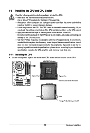
... Notch Triangle Pin One Marking on the computer if the CPU cooler is not recom- mended that the motherboard supports the CPU. (Go to GIGABYTE's website for the peripherals. Locate the alignment keys on the motherboard CPU socket and the notches on the CPU. 1-3 Installing the CPU and CPU Cooler Read the following...
... Notch Triangle Pin One Marking on the computer if the CPU cooler is not recom- mended that the motherboard supports the CPU. (Go to GIGABYTE's website for the peripherals. Locate the alignment keys on the motherboard CPU socket and the notches on the CPU. 1-3 Installing the CPU and CPU Cooler Read the following...

Manual
Page 14
... Step 1: Completely raise the CPU socket lever. Follow the steps below to the CPU. Step 3: Lift the metal load plate on the CPU socket. GA-EP35-DS3R/DS3 Motherboard - 14 - Before installing the CPU, make sure to turn off the computer and unplug the power cord from the power outlet to prevent damage to... insert the CPU into position. Step 5: Once the CPU is properly inserted, replace the load plate and push the CPU socket lever back into the motherboard CPU socket. Align the CPU pin one marking (triangle) with the pin one corner of the CPU socket (or you may align the CPU notches...
... Step 1: Completely raise the CPU socket lever. Follow the steps below to the CPU. Step 3: Lift the metal load plate on the CPU socket. GA-EP35-DS3R/DS3 Motherboard - 14 - Before installing the CPU, make sure to turn off the computer and unplug the power cord from the power outlet to prevent damage to... insert the CPU into position. Step 5: Once the CPU is properly inserted, replace the load plate and push the CPU socket lever back into the motherboard CPU socket. Align the CPU pin one marking (triangle) with the pin one corner of the CPU socket (or you may align the CPU notches...
Manual
Page 15
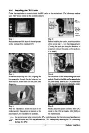
... installing the cooler, note the direction of the arrow sign on the male push pin. (Turning the push pin along the direction of the motherboard. Check that the Male and Female push pins are joined closely. (Refer to your CPU cooler installation manual for instructions on the push pins ... cooler and CPU may damage the CPU. - 15 - 1-3-2 Installing the CPU Cooler Follow the steps below to correctly install the CPU cooler on the motherboard. (The following procedure uses Intel® boxed cooler as the picture above, the installation is to install.) Step 3: Place the cooler atop the CPU,...
... installing the cooler, note the direction of the arrow sign on the male push pin. (Turning the push pin along the direction of the motherboard. Check that the Male and Female push pins are joined closely. (Refer to your CPU cooler installation manual for instructions on the push pins ... cooler and CPU may damage the CPU. - 15 - 1-3-2 Installing the CPU Cooler Follow the steps below to correctly install the CPU cooler on the motherboard. (The following procedure uses Intel® boxed cooler as the picture above, the installation is to install.) Step 3: Place the cooler atop the CPU,...
Manual
Page 16
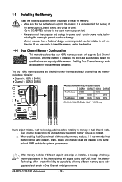
... DDR2 memory sockets and supports Dual Channel Technology. Enabling Dual Channel memory mode will appear during the POST. DS/SS - - GA-EP35-DS3R/DS3 Motherboard - 16 - After the memory is installed, the BIOS will automatically detect the specifications and capacity of the same capacity, brand,...Modules DS/SS - - DS/SS DS/SS (SS=Single-Sided, DS=Double-Sided, "- -"=No Memory) DDRII1 DDRII2 DDRII3 DDRII4 Due to GIGABYTE's website for optimum performance. The four DDR2 memory sockets are installed, a message which says memory is installed. 2. When memory modules of the same...
... DDR2 memory sockets and supports Dual Channel Technology. Enabling Dual Channel memory mode will appear during the POST. DS/SS - - GA-EP35-DS3R/DS3 Motherboard - 16 - After the memory is installed, the BIOS will automatically detect the specifications and capacity of the same capacity, brand,...Modules DS/SS - - DS/SS DS/SS (SS=Single-Sided, DS=Double-Sided, "- -"=No Memory) DDRII1 DDRII2 DDRII3 DDRII4 Due to GIGABYTE's website for optimum performance. The four DDR2 memory sockets are installed, a message which says memory is installed. 2. When memory modules of the same...

Manual
Page 17
... on the socket. Spread the retaining clips at both ends of the socket will snap into the memory socket. Place the memory module on this motherboard. As indicated in the memory sockets. 1-4-2 Installing a Memory Before installing a memory module , make sure to turn off the computer and unplug the power cord from...
... on the socket. Spread the retaining clips at both ends of the socket will snap into the memory socket. Place the memory module on this motherboard. As indicated in the memory sockets. 1-4-2 Installing a Memory Before installing a memory module , make sure to turn off the computer and unplug the power cord from...
Manual
Page 18
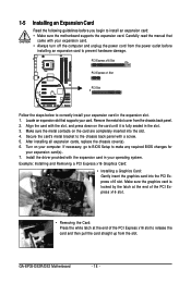
... an expansion slot that came with a screw. 5. If necessary, go to BIOS Setup to install an expansion card: • Make sure the motherboard supports the expansion card. Example: Installing and Removing a PCI Express x16 Graphics Card: • Installing a Graphics Card: Gently insert the graphics card...end of the PCI Express x16 slot to release the card and then pull the card straight up from the chassis back panel. 2. GA-EP35-DS3R/DS3 Motherboard - 18 - After installing all expansion cards, replace the chassis cover(s). 6. Install the driver provided with the slot, and press down...
... an expansion slot that came with a screw. 5. If necessary, go to BIOS Setup to install an expansion card: • Make sure the motherboard supports the expansion card. Example: Installing and Removing a PCI Express x16 Graphics Card: • Installing a Graphics Card: Gently insert the graphics card...end of the PCI Express x16 slot to release the card and then pull the card straight up from the chassis back panel. 2. GA-EP35-DS3R/DS3 Motherboard - 18 - After installing all expansion cards, replace the chassis cover(s). 6. Install the driver provided with the slot, and press down...
Manual
Page 19
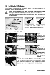
... bracket allows you only need to hardware. • Insert the SATA signal cable and SATA power cable securely into to the power connector on your motherboard. SATA Bracket SATA Signal Cable SATA Power Cable External SATA Connector Power Connector External SATA Connector The SATA bracket includes one SATA bracket, one SATA...
... bracket allows you only need to hardware. • Insert the SATA signal cable and SATA power cable securely into to the power connector on your motherboard. SATA Bracket SATA Signal Cable SATA Power Cable External SATA Connector Power Connector External SATA Connector The SATA bracket includes one SATA bracket, one SATA...
Manual
Page 20
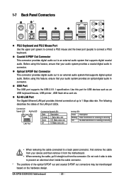
...8226; When removing the cable connected to a back panel connector, first remove the cable from your device and then remove it from the motherboard. • When removing the cable, pull it side to side to prevent an electrical short inside the cable connector. * The positions ...not rock it straight out from the connector. Use this feature, ensure that your audio system provides a coaxial digital audio in connector. GA-EP35-DS3R/DS3 Motherboard - 20 - Optical S/PDIF Out Connector This connector provides digital audio out to an external audio system that supports digital optical audio. ...
...8226; When removing the cable connected to a back panel connector, first remove the cable from your device and then remove it from the motherboard. • When removing the cable, pull it side to side to prevent an electrical short inside the cable connector. * The positions ...not rock it straight out from the connector. Use this feature, ensure that your audio system provides a coaxial digital audio in connector. GA-EP35-DS3R/DS3 Motherboard - 20 - Optical S/PDIF Out Connector This connector provides digital audio out to an external audio system that supports digital optical audio. ...
Manual
Page 22
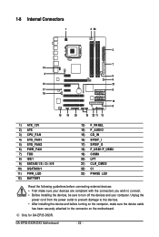
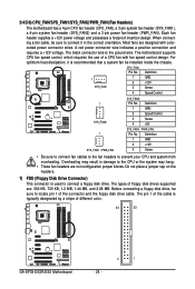
GA-EP35-DS3R/DS3 Motherboard - 22 - 1-8 Internal Connectors 1 3 23 2 7 14 4 5 6 12 21 17 9 16 10 8 15 19 20 18 22 11 13 1) ATX_12V 2) ATX 3) CPU_FAN 4) SYS_FAN1 5) SYS_FAN2 6) PWR_FAN 7) FDD 8) IDE1 9) ... to the connector on the motherboard. Unplug the power cord from the power outlet to prevent damage to the devices. • After installing the device and before connecting external devices: • First make sure the device cable has been securely attached to turn off the devices and your computer. Only for GA-EP35-DS3R.
GA-EP35-DS3R/DS3 Motherboard - 22 - 1-8 Internal Connectors 1 3 23 2 7 14 4 5 6 12 21 17 9 16 10 8 15 19 20 18 22 11 13 1) ATX_12V 2) ATX 3) CPU_FAN 4) SYS_FAN1 5) SYS_FAN2 6) PWR_FAN 7) FDD 8) IDE1 9) ... to the connector on the motherboard. Unplug the power cord from the power outlet to prevent damage to the devices. • After installing the device and before connecting external devices: • First make sure the device cable has been securely attached to turn off the devices and your computer. Only for GA-EP35-DS3R.
Manual
Page 23
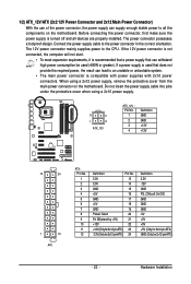
... power supply cable into pins under the protective cover when using a 2x12 power supply, remove the protective cover from the main power connector on the motherboard. Hardware Installation The 12V power connector mainly supplies power to the power connector in the correct orientation. If the 12V power connector is not connected... power connector possesses a foolproof design. Before connecting the power connector, first make sure the power supply is turned off and all the components on the motherboard.
... power supply cable into pins under the protective cover when using a 2x12 power supply, remove the protective cover from the main power connector on the motherboard. Hardware Installation The 12V power connector mainly supplies power to the power connector in the correct orientation. If the 12V power connector is not connected... power connector possesses a foolproof design. Before connecting the power connector, first make sure the power supply is turned off and all the components on the motherboard.
Manual
Page 24
...2 +12V 3 Sense • Be sure to connect fan cables to the fan headers to locate pin 1 of different color. 34 33 GA-EP35-DS3R/DS3 Motherboard 2 1 - 24 - A red power connector wire indicates a positive connection and requires a +12V voltage. The black connector wire is typically ... voltage and possesses a foolproof insertion design. The types of the cable is the ground wire. 3/4/5/6) CPU_FAN/SYS_FAN1/SYS_FAN2/PWR_FAN (Fan Headers) The motherboard has a 4-pin CPU fan header (CPU_FAN), a 3-pin system fan header (SYS_FAN1), a 4-pin system fan header (SYS_FAN2) and a 3-...
...2 +12V 3 Sense • Be sure to connect fan cables to the fan headers to locate pin 1 of different color. 34 33 GA-EP35-DS3R/DS3 Motherboard 2 1 - 24 - A red power connector wire indicates a positive connection and requires a +12V voltage. The black connector wire is typically ... voltage and possesses a foolproof insertion design. The types of the cable is the ground wire. 3/4/5/6) CPU_FAN/SYS_FAN1/SYS_FAN2/PWR_FAN (Fan Headers) The motherboard has a 4-pin CPU fan header (CPU_FAN), a 3-pin system fan header (SYS_FAN1), a 4-pin system fan header (SYS_FAN2) and a 3-...


