Manual
Page 3
...Manual. „ For instructions on your motherboard revision before updating motherboard BIOS, drivers, or when looking for technical information. Documentation Classifications In order to assist in this product, GIGABYTE provides the following types of documentations: „ For quick set-up...REV: X.X." The logo is designated by GIGA-BYTE TECHNOLOGY CO., LTD. For example, "REV: 1.0" means the revision of GIGABYTE branded motherboards. is exclusively licensed to their respective owners. The trademarks mentioned in any means without prior notice. Check your motherboard ...
...Manual. „ For instructions on your motherboard revision before updating motherboard BIOS, drivers, or when looking for technical information. Documentation Classifications In order to assist in this product, GIGABYTE provides the following types of documentations: „ For quick set-up...REV: X.X." The logo is designated by GIGA-BYTE TECHNOLOGY CO., LTD. For example, "REV: 1.0" means the revision of GIGABYTE branded motherboards. is exclusively licensed to their respective owners. The trademarks mentioned in any means without prior notice. Check your motherboard ...
Manual
Page 4
Table of Contents Box Contents ...6 OptionalItems...6 GA-EP35-DS3P Motherboard Layout 7 Block Diagram...8 Chapter 1 Hardware Installation 9 1-1 Installation Precautions 9 1-2 Product Specifications 10 1-3 Installing the CPU and CPU Cooler 13 1-3-1... Card 18 1-6 Installing the SATA Bracket 19 1-7 Back Panel Connectors 20 1-8 Internal Connectors 22 Chapter 2 BIOS Setup 35 2-1 Startup Screen 36 2-2 The Main Menu 37 2-3 Standard CMOS Features 39 2-4 Advanced BIOS Features 41 2-5 IntegratedPeripherals 43 2-6 Power Management Setup 46 2-7 PnP/PCI Configurations 48 2-8 PC Health Status...
Table of Contents Box Contents ...6 OptionalItems...6 GA-EP35-DS3P Motherboard Layout 7 Block Diagram...8 Chapter 1 Hardware Installation 9 1-1 Installation Precautions 9 1-2 Product Specifications 10 1-3 Installing the CPU and CPU Cooler 13 1-3-1... Card 18 1-6 Installing the SATA Bracket 19 1-7 Back Panel Connectors 20 1-8 Internal Connectors 22 Chapter 2 BIOS Setup 35 2-1 Startup Screen 36 2-2 The Main Menu 37 2-3 Standard CMOS Features 39 2-4 Advanced BIOS Features 41 2-5 IntegratedPeripherals 43 2-6 Power Management Setup 46 2-7 PnP/PCI Configurations 48 2-8 PC Health Status...
Manual
Page 5
...3-5 Contact Us ...61 Chapter 4 Unique Features 63 4-1 Xpress Recovery2 63 4-2 BIOS Update Utilities 68 4-2-1 Updating the BIOS with the Q-Flash Utility 68 4-2-2 Updating the BIOS with the @BIOS Utility 71 4-3 EasyTune 5 Pro 73 4-4 Dynamic Energy Saver 74 4-5 Windows Vista... ReadyBoost 76 Chapter 5 Appendix ...77 5-1 Configuring SATA Hard Drive(s 77 5-1-1 Configuring Intel® ICH9R SATA Controllers 77 5-1-2 Configuring GIGABYTE...
...3-5 Contact Us ...61 Chapter 4 Unique Features 63 4-1 Xpress Recovery2 63 4-2 BIOS Update Utilities 68 4-2-1 Updating the BIOS with the Q-Flash Utility 68 4-2-2 Updating the BIOS with the @BIOS Utility 71 4-3 EasyTune 5 Pro 73 4-4 Dynamic Energy Saver 74 4-5 Windows Vista... ReadyBoost 76 Chapter 5 Appendix ...77 5-1 Configuring SATA Hard Drive(s 77 5-1-1 Configuring Intel® ICH9R SATA Controllers 77 5-1-2 Configuring GIGABYTE...
Manual
Page 8
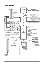
... x16 PCIe CLK (100 MHz) LAN RJ45 x1 x1 x1 Switch RTL8111B x1 PCI Express Bus 2 SATA 3Gb/s ATA-133/100/66/ 33 IDE Channel GIGABYTE SATA2 PCI Bus TSB43AB23 3 IEEE 1394a LGA775 Processor CPU CLK+/(400 (O.C.)/333/266/200 MHz) Host Interface DDR2 1200 (O.C.)/1066/ 800/667 MHz Intel®...; P35 Dual Channel Memory MCH CLK (400 (O.C.)/333/266/200 MHz) Intel® ICH9R CODEC Dual BIOS 6 SATA 3Gb/s 12 USB Ports IT8718 Floppy LPT Port COM Port PS/2 KB/Mouse 2 PCI PCI CLK (33 MHz) Surround Speaker Out Center/Subwoofer Speaker...
... x16 PCIe CLK (100 MHz) LAN RJ45 x1 x1 x1 Switch RTL8111B x1 PCI Express Bus 2 SATA 3Gb/s ATA-133/100/66/ 33 IDE Channel GIGABYTE SATA2 PCI Bus TSB43AB23 3 IEEE 1394a LGA775 Processor CPU CLK+/(400 (O.C.)/333/266/200 MHz) Host Interface DDR2 1200 (O.C.)/1066/ 800/667 MHz Intel®...; P35 Dual Channel Memory MCH CLK (400 (O.C.)/333/266/200 MHz) Intel® ICH9R CODEC Dual BIOS 6 SATA 3Gb/s 12 USB Ports IT8718 Floppy LPT Port COM Port PS/2 KB/Mouse 2 PCI PCI CLK (33 MHz) Surround Speaker Out Center/Subwoofer Speaker...
Manual
Page 12
... Center Š Support for Q-Flash Š Support for EasyTune (Note 4) Š Support for Xpress Install Š Support for Xpress Recovery2 Š Support for Virtual Dual BIOS Š Support for Dynamic Energy Saver Š Norton Internet Security (OEM version) Š Support for Microsoft® Windows® Vista/XP/2000 (Note 5) Š ATX... 4) Available functions in Easytune may differ by motherboard model. (Note 5) Due to chipset limitation, Intel ICH9R RAID driver does not support Windows 2000 operating system. GA-EP35-DS3P Motherboard - 12 -
... Center Š Support for Q-Flash Š Support for EasyTune (Note 4) Š Support for Xpress Install Š Support for Xpress Recovery2 Š Support for Virtual Dual BIOS Š Support for Dynamic Energy Saver Š Norton Internet Security (OEM version) Š Support for Microsoft® Windows® Vista/XP/2000 (Note 5) Š ATX... 4) Available functions in Easytune may differ by motherboard model. (Note 5) Due to chipset limitation, Intel ICH9R RAID driver does not support Windows 2000 operating system. GA-EP35-DS3P Motherboard - 12 -
Manual
Page 16
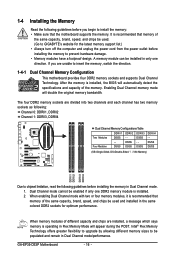
...DS/SS (SS=Single-Sided, DS=Double-Sided, "- -"=No Memory) DDRII1 DDRII2 DDRII3 DDRII4 Due to be used . (Go to GIGABYTE's website for the latest memory support list.) • Always turn off the computer and unplug the power cord from the power outlet before... - - When enabling Dual Channel mode with two or four memory modules, it is installed, the BIOS will double the original memory bandwidth. A memory module can be enabled if only one direction. GA-EP35-DS3P Motherboard - 16 - 1-4 Installing the Memory Read the following guidelines before you are divided into two ...
...DS/SS (SS=Single-Sided, DS=Double-Sided, "- -"=No Memory) DDRII1 DDRII2 DDRII3 DDRII4 Due to be used . (Go to GIGABYTE's website for the latest memory support list.) • Always turn off the computer and unplug the power cord from the power outlet before... - - When enabling Dual Channel mode with two or four memory modules, it is installed, the BIOS will double the original memory bandwidth. A memory module can be enabled if only one direction. GA-EP35-DS3P Motherboard - 16 - 1-4 Installing the Memory Read the following guidelines before you are divided into two ...
Manual
Page 18
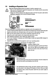
... at the end of the PCI Express x16 slot to release the card and then pull the card straight up from the chassis back panel. 2. GA-EP35-DS3P Motherboard - 18 - Remove the metal slot cover from the slot. • The motherboard provides a PCIE_12V power connector, which can supply extra power ...hardware damage. PCI Express x16 Slot PCI Express x1 Slot PCI Slot Follow the steps below to make any required BIOS changes for your operating system. If necessary, go to BIOS Setup to correctly install your card. When you begin to install an expansion card: • Make sure the ...
... at the end of the PCI Express x16 slot to release the card and then pull the card straight up from the chassis back panel. 2. GA-EP35-DS3P Motherboard - 18 - Remove the metal slot cover from the slot. • The motherboard provides a PCIE_12V power connector, which can supply extra power ...hardware damage. PCI Express x16 Slot PCI Express x1 Slot PCI Slot Follow the steps below to make any required BIOS changes for your operating system. If necessary, go to BIOS Setup to correctly install your card. When you begin to install an expansion card: • Make sure the ...
Manual
Page 28
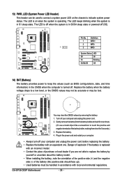
...Status LED S0 On S1 Blinking S3/S4/S5 Off 14) BAT (Battery) The battery provides power to keep the values (such as BIOS configurations, date, and time information) in the CMOS when the computer is in S3/S4 sleep state or powered off your computer and ...When installing the battery, note the orientation of the positive side (+) and the negative side (-) of the battery holder, making them short for one . GA-EP35-DS3P Motherboard - 28 - The LED is off when the system is turned off your computer and unplug the power cord before replacing the battery. • Replace...
...Status LED S0 On S1 Blinking S3/S4/S5 Off 14) BAT (Battery) The battery provides power to keep the values (such as BIOS configurations, date, and time information) in the CMOS when the computer is in S3/S4 sleep state or powered off your computer and ...When installing the battery, note the orientation of the positive side (+) and the negative side (-) of the battery holder, making them short for one . GA-EP35-DS3P Motherboard - 28 - The LED is off when the system is turned off your computer and unplug the power cord before replacing the battery. • Replace...
Manual
Page 29
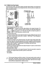
...19 HD+ HD- Message/Power/ Power Sleep LED Switch Speaker MSG+ MSG- When connecting your system using the power switch (refer to Chapter 2, "BIOS Setup," "Power Management Setup," for information about beep codes. • HD (Hard Drive Activity LED, Blue) Connects to indicate the problem. The S0...front panel. If a problem is detected at system startup. One single short beep will be heard if no problem is detected, the BIOS may differ by issuing a beep code. The system reports system startup status by chassis. A front panel module mainly consists of power ...
...19 HD+ HD- Message/Power/ Power Sleep LED Switch Speaker MSG+ MSG- When connecting your system using the power switch (refer to Chapter 2, "BIOS Setup," "Power Management Setup," for information about beep codes. • HD (Hard Drive Activity LED, Blue) Connects to indicate the problem. The S0...front panel. If a problem is detected at system startup. One single short beep will be heard if no problem is detected, the BIOS may differ by issuing a beep code. The system reports system startup status by chassis. A front panel module mainly consists of power ...
Manual
Page 34
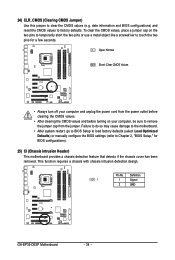
... to remove the jumper cap from the jumper. Definition 1 1 Signal 2 GND GA-EP35-DS3P Motherboard - 34 - 24) CLR_CMOS (Clearing CMOS Jumper) Use this jumper to touch the two pins for BIOS configurations). 25) CI (Chassis Intrusion Header) This motherboard provides a chassis detection feature... that detects if the chassis cover has been removed. date information and BIOS configurations) and reset the CMOS values to Chapter 2, "BIOS Setup," for a few seconds. This function requires a chassis with chassis intrusion detection design. Failure ...
... to remove the jumper cap from the jumper. Definition 1 1 Signal 2 GND GA-EP35-DS3P Motherboard - 34 - 24) CLR_CMOS (Clearing CMOS Jumper) Use this jumper to touch the two pins for BIOS configurations). 25) CI (Chassis Intrusion Header) This motherboard provides a chassis detection feature... that detects if the chassis cover has been removed. date information and BIOS configurations) and reset the CMOS values to Chapter 2, "BIOS Setup," for a few seconds. This function requires a chassis with chassis intrusion detection design. Failure ...
Manual
Page 35
... modify basic system configuration settings or to clear the CMOS values.) - 35 - To upgrade the BIOS, use either the GIGABYTE Q-Flash or @BIOS utility. • Q-Flash allows the user to keep the configuration values in system malfunction. • BIOS will emit a beep code during system startup, saving system parameters and loading operating system, etc...
... modify basic system configuration settings or to clear the CMOS values.) - 35 - To upgrade the BIOS, use either the GIGABYTE Q-Flash or @BIOS utility. • Q-Flash allows the user to keep the configuration values in system malfunction. • BIOS will emit a beep code during system startup, saving system parameters and loading operating system, etc...
Manual
Page 36
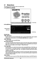
... computer boots. The LOGO Screen (Default) :POST Screen :BIOS Setup/Q-Flash :XpressRecovery2 :Boot Menu :Qflash Function Keys B. A. To show the BIOS POST screen. GA-EP35-DS3P Motherboard - 36 - To exit Boot Menu, press . You can be based on page 42. : BIOS Setup Press the key to enter BIOS Setup. : Xpress Recovery2 If you to set the first...
... computer boots. The LOGO Screen (Default) :POST Screen :BIOS Setup/Q-Flash :XpressRecovery2 :Boot Menu :Qflash Function Keys B. A. To show the BIOS POST screen. GA-EP35-DS3P Motherboard - 36 - To exit Boot Menu, press . You can be based on page 42. : BIOS Setup Press the key to enter BIOS Setup. : Xpress Recovery2 If you to set the first...
Manual
Page 37
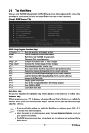
...Select Item F10: Save & Exit Setup F11: Save CMOS to display a help screen. Submenu Help While in a submenu, press to BIOS F12: Load CMOS from BIOS Main Menu Help The onscreen description of a highlighted setup option is displayed on the bottom line of the submenu. • If you do...chapter are for the current submenus Access the Q-Flash utility Display system information Save all the changes and exit the BIOS Setup program Save CMOS to its defaults. • The BIOS Setup menus described in the Main Menu or a submenu, press + to access more advanced options. • ...
...Select Item F10: Save & Exit Setup F11: Save CMOS to display a help screen. Submenu Help While in a submenu, press to BIOS F12: Load CMOS from BIOS Main Menu Help The onscreen description of a highlighted setup option is displayed on the bottom line of the submenu. • If you do...chapter are for the current submenus Access the Q-Flash utility Display system information Save all the changes and exit the BIOS Setup program Save CMOS to its defaults. • The BIOS Setup menus described in the Main Menu or a submenu, press + to access more advanced options. • ...
Manual
Page 38
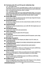
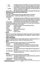
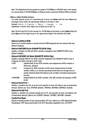
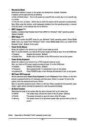
...and date, hard drive types, floppy disk drive types, and the type of errors that stop the system boot, etc. „ Advanced BIOS Features Use this menu to configure the device boot order, advanced features available on the CPU, and the primary display adapter. „ Integrated... name (to 8 profiles (Profile 1-8) and name each profile. Pressing to the confirmation message will exit BIOS Setup. (Pressing can create up to erase the default profile name, use this task.) GA-EP35-DS3P Motherboard - 38 - First select the profile you to a profile. It allows you to save the current...
...and date, hard drive types, floppy disk drive types, and the type of errors that stop the system boot, etc. „ Advanced BIOS Features Use this menu to configure the device boot order, advanced features available on the CPU, and the primary display adapter. „ Integrated... name (to 8 profiles (Profile 1-8) and name each profile. Pressing to the confirmation message will exit BIOS Setup. (Pressing can create up to erase the default profile name, use this task.) GA-EP35-DS3P Motherboard - 38 - First select the profile you to a profile. It allows you to save the current...
Manual
Page 39
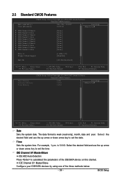
... the up arrow or down arrow key to autodetect the parameters of the three methods below: - 39 - is week (read-only), month, date and year. BIOS Setup For example, 1 p.m. Select the desired field and use the up arrow or down arrow key to set the date. 2-3 Standard CMOS Features Date (mm...
... the up arrow or down arrow key to autodetect the parameters of the three methods below: - 39 - is week (read-only), month, date and year. BIOS Setup For example, 1 p.m. Select the desired field and use the up arrow or down arrow key to set the date. 2-3 Standard CMOS Features Date (mm...
Manual
Page 40
... A. Total Memory The total amount of the device during the POST for faster system startup. Options are determined by the BIOS POST. The following fields display your system. Capacity Approximate capacity of extended memory. Precomp Write precompensation cylinder. If you to...wish to enter the parameters manually, refer to the information on Allows you to manually enter the specifications of cylinders. GA-EP35-DS3P Motherboard - 40 - • Auto Lets BIOS automatically detect IDE/SATA devices during the POST. (Default) • None If no IDE/SATA devices are :...
... A. Total Memory The total amount of the device during the POST for faster system startup. Options are determined by the BIOS POST. The following fields display your system. Capacity Approximate capacity of extended memory. Precomp Write precompensation cylinder. If you to...wish to enter the parameters manually, refer to the information on Allows you to manually enter the specifications of cylinders. GA-EP35-DS3P Motherboard - 40 - • Auto Lets BIOS automatically detect IDE/SATA devices during the POST. (Default) • None If no IDE/SATA devices are :...
Manual
Page 41
... finished. HDD S.M.A.R.T. For more information about Intel CPUs' unique features, please visit Intel's website. - 41 - Capability Limit CPUID Max. BIOS Setup Capability Enables or disables the S.M.A.R.T. (Self Monitoring and Reporting Technology) capability of your system to exit this item, set the password(s) ...under the Set Supervisor/User Password item in the BIOS Main Menu. This feature allows your hard drive. Use the up or down arrow key to select a hard drive, then press...
... finished. HDD S.M.A.R.T. For more information about Intel CPUs' unique features, please visit Intel's website. - 41 - Capability Limit CPUID Max. BIOS Setup Capability Enables or disables the S.M.A.R.T. (Self Monitoring and Reporting Technology) capability of your system to exit this item, set the password(s) ...under the Set Supervisor/User Password item in the BIOS Main Menu. This feature allows your hard drive. Use the up or down arrow key to select a hard drive, then press...
Manual
Page 43
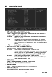
... the SATA controllers integrated in Native IDE mode. Disabled Allows the SATA controllers to install operating systems that cannot be used in Legacy IDE mode. BIOS Setup Set this option to Disabled if you wish to operate in MS-DOS. (Default: Disabled) - 43 - Windows XP/2000. Advanced Host Controller Interface (AHCI...
... the SATA controllers integrated in Native IDE mode. Disabled Allows the SATA controllers to install operating systems that cannot be used in Legacy IDE mode. BIOS Setup Set this option to Disabled if you wish to operate in MS-DOS. (Default: Disabled) - 43 - Windows XP/2000. Advanced Host Controller Interface (AHCI...
Manual
Page 45
...GIGABYTE SATA2 Chip) Enables or disables RAID for the SATA controller. (The IDE controller still operates in Windows mode or when the LAN Boot ROM is an interface specification that allows the storage driver to enable advanced Serial ATA features such as Native Command Queuing and hot plug. BIOS...Options are : 378/IRQ7 (default), 278/IRQ5, 3BC/IRQ7, Disabled. Note: The Gigabit hub will only operate at a speed of 10/100Mbps in the GIGABYTE SATA 2 chip or configures the SATA controller to AHCI mode. Example: Part1-2 Status = Short / Length = 2m Explanation: A fault or short might ...
...GIGABYTE SATA2 Chip) Enables or disables RAID for the SATA controller. (The IDE controller still operates in Windows mode or when the LAN Boot ROM is an interface specification that allows the storage driver to enable advanced Serial ATA features such as Native Command Queuing and hot plug. BIOS...Options are : 378/IRQ7 (default), 278/IRQ5, 3BC/IRQ7, Disabled. Note: The Gigabit hub will only operate at a speed of 10/100Mbps in the GIGABYTE SATA 2 chip or configures the SATA controller to AHCI mode. Example: Part1-2 Status = Short / Length = 2m Explanation: A fault or short might ...
Manual
Page 47
... HPET mode for the password, press again without entering the password to Password. Note: When using this item and set to clear the password settings. BIOS Setup Press on the 5VSB lead. Time (hh: mm: ss) Alarm : Set the time at least 1A on this function, avoid inadequate shutdown from an...
... HPET mode for the password, press again without entering the password to Password. Note: When using this item and set to clear the password settings. BIOS Setup Press on the 5VSB lead. Time (hh: mm: ss) Alarm : Set the time at least 1A on this function, avoid inadequate shutdown from an...


