Manual
Page 3
... product, GIGABYTE provides the following types of GIGABYTE. The trademarks mentioned in any form or by any means without prior notice. Documentation Classifications In order to their respective owners. Check your motherboard looks like this: "REV: X.X." Changes to the specifications and features...documentations: For detailed product information, carefully read the User's Manual. For instructions on how to use GIGABYTE's unique features, read or download the information on/from the Support&Downloads\Motherboard\Technology Guide page on your motherboard revision before ...
... product, GIGABYTE provides the following types of GIGABYTE. The trademarks mentioned in any form or by any means without prior notice. Documentation Classifications In order to their respective owners. Check your motherboard looks like this: "REV: X.X." Changes to the specifications and features...documentations: For detailed product information, carefully read the User's Manual. For instructions on how to use GIGABYTE's unique features, read or download the information on/from the Support&Downloads\Motherboard\Technology Guide page on your motherboard revision before ...
Manual
Page 4
Table of Contents Box Contents ...6 OptionalItems...6 GA-EP31-DS3L Motherboard Layout 7 Block Diagram...8 Chapter 1 Hardware Installation 9 1-1 Installation Precautions 9 1-2 Product Specifications 10 1-3 Installing the CPU and CPU Cooler 13 1-3-1 Installing the CPU 13 1-3-2 Installing the CPU Cooler 15 1-4 Installing the Memory 16 1-4-1 Dual Channel Memory Configuration ...
Table of Contents Box Contents ...6 OptionalItems...6 GA-EP31-DS3L Motherboard Layout 7 Block Diagram...8 Chapter 1 Hardware Installation 9 1-1 Installation Precautions 9 1-2 Product Specifications 10 1-3 Installing the CPU and CPU Cooler 13 1-3-1 Installing the CPU 13 1-3-2 Installing the CPU Cooler 15 1-4 Installing the Memory 16 1-4-1 Dual Channel Memory Configuration ...

Manual
Page 10
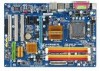
1-2 Product Specifications CPU Front Side Bus Chipset Memory Audio LAN Expansion Slots Storage Interface USB Š Support for an Intel® CoreTM ... 4 GB of system memory (Note 1) Š Dual channel memory architecture Š Support for DDR2 1066/800/667 MHz memory modules (Go to GIGABYTE's website for the latest memory support list.) Š Realtek ALC888 codec Š High Definition Audio Š 2/4/5.1/7.1-channel Š Support for S/PDIF...138; Up to 8 USB 2.0/1.1 ports (4 on the back panel, 4 via the USB brackets connected to the internal USB headers) GA-EP31-DS3L Motherboard - 10 -
1-2 Product Specifications CPU Front Side Bus Chipset Memory Audio LAN Expansion Slots Storage Interface USB Š Support for an Intel® CoreTM ... 4 GB of system memory (Note 1) Š Dual channel memory architecture Š Support for DDR2 1066/800/667 MHz memory modules (Go to GIGABYTE's website for the latest memory support list.) Š Realtek ALC888 codec Š High Definition Audio Š 2/4/5.1/7.1-channel Š Support for S/PDIF...138; Up to 8 USB 2.0/1.1 ports (4 on the back panel, 4 via the USB brackets connected to the internal USB headers) GA-EP31-DS3L Motherboard - 10 -

Manual
Page 13
...• Make sure that the system bus frequency be inserted if oriented incorrectly. (Or you wish to GIGABYTE's website for the peripherals. The CPU cannot be set the frequency beyond hardware specifications since it does not meet the standard requirements for the latest CPU support list.) • Always turn ... if the CPU cooler is not recom- If you may occur. • Set the CPU host frequency in accordance with the CPU specifications. LGA775 CPU Socket Alignment Key LGA 775 CPU Alignment Key Pin One Corner of the CPU Socket Notch Notch Triangle Pin One Marking on...
...• Make sure that the system bus frequency be inserted if oriented incorrectly. (Or you wish to GIGABYTE's website for the peripherals. The CPU cannot be set the frequency beyond hardware specifications since it does not meet the standard requirements for the latest CPU support list.) • Always turn ... if the CPU cooler is not recom- If you may occur. • Set the CPU host frequency in accordance with the CPU specifications. LGA775 CPU Socket Alignment Key LGA 775 CPU Alignment Key Pin One Corner of the CPU Socket Notch Notch Triangle Pin One Marking on...
Manual
Page 16
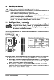
It is installed. 2. DS/SS - - GA-EP31-DS3L Motherboard - 16 - Dual Channel mode cannot be installed in only one DDR2 memory module is recommended that memory of the same capacity, brand, speed, and chips be used . (Go to GIGABYTE's website for optimum performance. 3. 1-4 Installing the Memory Read the following ...memory: • Make sure that memory of memory modules. DS/SS - - Enabling Dual Channel memory mode will automatically detect the specifications and capacity of the same channel (e.g. A memory module can be enabled if only one direction.
It is installed. 2. DS/SS - - GA-EP31-DS3L Motherboard - 16 - Dual Channel mode cannot be installed in only one DDR2 memory module is recommended that memory of the same capacity, brand, speed, and chips be used . (Go to GIGABYTE's website for optimum performance. 3. 1-4 Installing the Memory Read the following ...memory: • Make sure that memory of memory modules. DS/SS - - Enabling Dual Channel memory mode will automatically detect the specifications and capacity of the same channel (e.g. A memory module can be enabled if only one direction.

Manual
Page 19
... port for USB devices such as an USB keyboard/mouse, USB printer, USB flash drive and etc. USB Port The USB port supports the USB 2.0/1.1 specification. Parallel Port Use the parallel port to prevent an electrical short inside the cable connector. - 19 -
... port for USB devices such as an USB keyboard/mouse, USB printer, USB flash drive and etc. USB Port The USB port supports the USB 2.0/1.1 specification. Parallel Port Use the parallel port to prevent an electrical short inside the cable connector. - 19 -
Manual
Page 28
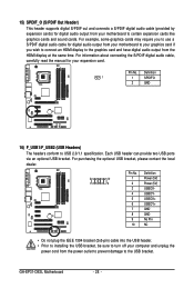
Definition 1 1 SPDIFO 2 GND 16) F_USB1/F_USB2 (USB Headers) The headers conform to USB 2.0/1.1 specification. GA-EP31-DS3L Motherboard - 28 - Pin No. For purchasing the optional USB bracket, please contact the local dealer. 2 10 1 9 Pin No. 1 2 3 4 5 6 7 8 9 10 Definition Power (5V) Power (5V) USB ...
Definition 1 1 SPDIFO 2 GND 16) F_USB1/F_USB2 (USB Headers) The headers conform to USB 2.0/1.1 specification. GA-EP31-DS3L Motherboard - 28 - Pin No. For purchasing the optional USB bracket, please contact the local dealer. 2 10 1 9 Pin No. 1 2 3 4 5 6 7 8 9 10 Definition Power (5V) Power (5V) USB ...
Manual
Page 35
... IDE/SATA devices are used , set the date. IDE Channel 0 Master/Slave IDE HDD Auto-Detection Press to CHS. Allows you to manually enter the specifications of the IDE/SATA device on this channel. is week (read-only), month, date and year. IDE Channel 2, 3 Master/Slave IDE Auto-Detection Press to...
... IDE/SATA devices are used , set the date. IDE Channel 0 Master/Slave IDE HDD Auto-Detection Press to CHS. Allows you to manually enter the specifications of the IDE/SATA device on this channel. is week (read-only), month, date and year. IDE Channel 2, 3 Master/Slave IDE Auto-Detection Press to...

Manual
Page 36
Head Number of extended memory. Floppy 3 Mode Support Allows you to selects the type of floppy disk drive installed in your hard drive specifications. No Errors The system boot will stop for a keyboard or a floppy disk drive error but it will not stop . All, But ...disk drive is 3-mode floppy disk drive, a Japanese standard floppy disk drive. Memory These fields are read-only and are : Disabled (default), Drive A. GA-EP31-DS3L Motherboard - 36 - Landing Zone Landing zone. All Errors Whenever the BIOS detects a non-fatal error the system boot will not stop for a floppy ...
Head Number of extended memory. Floppy 3 Mode Support Allows you to selects the type of floppy disk drive installed in your hard drive specifications. No Errors The system boot will stop for a keyboard or a floppy disk drive error but it will not stop . All, But ...disk drive is 3-mode floppy disk drive, a Japanese standard floppy disk drive. Memory These fields are read-only and are : Disabled (default), Drive A. GA-EP31-DS3L Motherboard - 36 - Landing Zone Landing zone. All Errors Whenever the BIOS detects a non-fatal error the system boot will not stop for a floppy ...
Manual
Page 38
...Enabled) Init Display First Specifies the first initiation of the monitor display from the installed PCI graphics card or PCI Express graphics card. GA-EP31-DS3L Motherboard - 38 - Limit CPUID Max. Set this feature. PCI Sets the PCI graphics card as the first display. (Default) ... When enabled, the CPU core frequency and voltage will be reduced during system halt state to display the GIGABYTE Logo at system startup. Disabled sets the CPU voltage following Intel specifications. (Default: Disabled) CPU Enhanced Halt (C1E) (Note) Enables or disables Intel® CPU Enhanced Halt...
...Enabled) Init Display First Specifies the first initiation of the monitor display from the installed PCI graphics card or PCI Express graphics card. GA-EP31-DS3L Motherboard - 38 - Limit CPUID Max. Set this feature. PCI Sets the PCI graphics card as the first display. (Default) ... When enabled, the CPU core frequency and voltage will be reduced during system halt state to display the GIGABYTE Logo at system startup. Disabled sets the CPU voltage following Intel specifications. (Default: Disabled) CPU Enhanced Halt (C1E) (Note) Enables or disables Intel® CPU Enhanced Halt...

Manual
Page 43
... Double click on left button on the PS/2 mouse to turn on this function, you need an ATX power supply providing at a specific time on each day or on a specific day in a month. Memory The system returns to its last known awake state upon the return of power from the operating system...
... Double click on left button on the PS/2 mouse to turn on this function, you need an ATX power supply providing at a specific time on each day or on a specific day in a month. Memory The system returns to its last known awake state upon the return of power from the operating system...

Manual
Page 48
...to operate at its best performance level. Disabled Disables the use of C.I .A.2, please first verify the overclocking capability of your CPU. GA-EP31-DS3L Motherboard - 48 - Performance Enhance Allows the system to 700 MHz. This item is configurable only if the CPU Host Clock Control ... the board to default values. (Default: Disabled) CPU Host Frequency (Mhz) Allows you to manually set in accordance with the CPU specifications. Note: If your computer. The adjustable range is designed to automatically adjust CPU computing power to 266 MHz. For a 1066 MHz ...
...to operate at its best performance level. Disabled Disables the use of C.I .A.2, please first verify the overclocking capability of your CPU. GA-EP31-DS3L Motherboard - 48 - Performance Enhance Allows the system to 700 MHz. This item is configurable only if the CPU Host Clock Control ... the board to default values. (Default: Disabled) CPU Host Frequency (Mhz) Allows you to manually set in accordance with the CPU specifications. Note: If your computer. The adjustable range is designed to automatically adjust CPU computing power to 266 MHz. For a 1066 MHz ...

Manual
Page 74
... In in Master Volume, go to complete. To hear the sound being recorded during the recording process when using the microphone function on the audio specifications, to adjust the recording sound, use the Recording option to the Options menu and then choose Properties. In the Mixer device list, select Realtek HD... being recorded during the record- Then set the recording sound for your recording device(s) altogether. Step 5: Next, while in the Mixer device list Recording Control GA-EP31-DS3L Motherboard - 74 -
... In in Master Volume, go to complete. To hear the sound being recorded during the recording process when using the microphone function on the audio specifications, to adjust the recording sound, use the Recording option to the Options menu and then choose Properties. In the Mixer device list, select Realtek HD... being recorded during the record- Then set the recording sound for your recording device(s) altogether. Step 5: Next, while in the Mixer device list Recording Control GA-EP31-DS3L Motherboard - 74 -