Manual
Page 1
GA-EG41MF-S2H LGA775 socket motherboard for Intel® CoreTM processor family/ Intel® Pentium® processor family/Intel® Celeron® processor family User's Manual Rev. 1002 12ME-EG41MFS2H-1002R
GA-EG41MF-S2H LGA775 socket motherboard for Intel® CoreTM processor family/ Intel® Pentium® processor family/Intel® Celeron® processor family User's Manual Rev. 1002 12ME-EG41MFS2H-1002R

Manual
Page 2
Motherboard GA-EG41MF-S2H Oct. 22, 2008 Motherboard GA-EG41MF-S2H Oct. 22, 2008
Motherboard GA-EG41MF-S2H Oct. 22, 2008 Motherboard GA-EG41MF-S2H Oct. 22, 2008

Manual
Page 3
... this manual is protected by GIGABYTE without GIGABYTE's prior written permission. The trademarks mentioned in the use GIGABYTE's unique features, read or download the information on/from the Support\Motherboard\Technology Guide page on your motherboard revision before updating motherboard BIOS, drivers, or when...related information, check on our website at: http://www.gigabyte.com.tw Identifying Your Motherboard Revision The revision number on our website. All rights reserved. No part of this product, GIGABYTE provides the following types of documentations: For ...
... this manual is protected by GIGABYTE without GIGABYTE's prior written permission. The trademarks mentioned in the use GIGABYTE's unique features, read or download the information on/from the Support\Motherboard\Technology Guide page on your motherboard revision before updating motherboard BIOS, drivers, or when...related information, check on our website at: http://www.gigabyte.com.tw Identifying Your Motherboard Revision The revision number on our website. All rights reserved. No part of this product, GIGABYTE provides the following types of documentations: For ...

Manual
Page 4
Table of Contents Box Contents ...6 OptionalItems ...6 GA-EG41MF-S2H Motherboard Layout 7 Block Diagram ...8 Chapter 1 Hardware Installation 9 1-1 Installation Precautions 9 1-2 Product Specifications 10 1-3 Installing the CPU and CPU Cooler 13 1-3-1 Installing the CPU 13 1-3-2 Installing the CPU ...
Table of Contents Box Contents ...6 OptionalItems ...6 GA-EG41MF-S2H Motherboard Layout 7 Block Diagram ...8 Chapter 1 Hardware Installation 9 1-1 Installation Precautions 9 1-2 Product Specifications 10 1-3 Installing the CPU and CPU Cooler 13 1-3-1 Installing the CPU 13 1-3-2 Installing the CPU ...

Manual
Page 6
... power cable (Part No. 12CF1-2SERPW-01R) S/PDIF in cable (Part No. 12CR1-1SPDIN-01R) COM port cable (Part No. 12CF1-1CM001-32R) - 6 - Box Contents GA-EG41MF-S2H motherboard Motherboard driver disk User's Manual One IDE cable and one floppy disk drive cable Two SATA 3Gb/s cables I/O Shield • The box contents above are subject...
... power cable (Part No. 12CF1-2SERPW-01R) S/PDIF in cable (Part No. 12CR1-1SPDIN-01R) COM port cable (Part No. 12CF1-1CM001-32R) - 6 - Box Contents GA-EG41MF-S2H motherboard Motherboard driver disk User's Manual One IDE cable and one floppy disk drive cable Two SATA 3Gb/s cables I/O Shield • The box contents above are subject...

Manual
Page 7
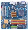
GA-EG41MF-S2H Motherboard Layout KB_MS PHASE LED IT8718 ATX_12V LGA775 FDD VGA LAN DVI HDMI Level Shifter OPTICAL SiI1392 USB_1394 BATTERY USB AUDIO F_AUDIO CPU_FAN PCIE_1 RTL8111C PCIE_16 PCI1 SPDIF_O PCI2 CODEC CD_IN SPDIF_I COMA GA-EG41MF-S2H Intel® G41 B_BIOS M_BIOS TSB43AB23 Intel® ICH7 CI DDR2_1 DDR2_2 DDR2_3 DDR2_4 IDE ATX SYS_FAN SATA2_1 SATA2_3 SATA2_0 SATA2_2 CLR_CMOS F1_1394 F_USB1 F_USB2 PWR_LED F_PANEL - 7 -
GA-EG41MF-S2H Motherboard Layout KB_MS PHASE LED IT8718 ATX_12V LGA775 FDD VGA LAN DVI HDMI Level Shifter OPTICAL SiI1392 USB_1394 BATTERY USB AUDIO F_AUDIO CPU_FAN PCIE_1 RTL8111C PCIE_16 PCI1 SPDIF_O PCI2 CODEC CD_IN SPDIF_I COMA GA-EG41MF-S2H Intel® G41 B_BIOS M_BIOS TSB43AB23 Intel® ICH7 CI DDR2_1 DDR2_2 DDR2_3 DDR2_4 IDE ATX SYS_FAN SATA2_1 SATA2_3 SATA2_0 SATA2_2 CLR_CMOS F1_1394 F_USB1 F_USB2 PWR_LED F_PANEL - 7 -

Manual
Page 9
... the installation process can become damaged as a result of your hardware components are connected. • To prevent damage to the motherboard, do not have an ESD wrist strap, keep your hands dry and first touch a metal object to eliminate static electricity. ... please verify that all cables and power connectors of electrostatic discharge (ESD). Hardware Installation Chapter 1 Hardware Installation 1-1 Installation Precautions The motherboard contains numerous delicate electronic circuits and components which can lead to damage to the use of an antistatic pad or within the computer...
... the installation process can become damaged as a result of your hardware components are connected. • To prevent damage to the motherboard, do not have an ESD wrist strap, keep your hands dry and first touch a metal object to eliminate static electricity. ... please verify that all cables and power connectors of electrostatic discharge (ESD). Hardware Installation Chapter 1 Hardware Installation 1-1 Installation Precautions The motherboard contains numerous delicate electronic circuits and components which can lead to damage to the use of an antistatic pad or within the computer...
Manual
Page 10
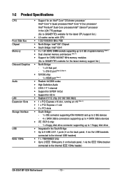
...174; Pentium® Dual-Core processo/Intel® Celeron® processor in the LGA 775 package (Go to GIGABYTE's website for the latest CPU support list.) L2 cache varies with CPU 1333/1066/800 MHz... 8 GB of system memory (Note 1) Dual channel memory architecture (Note 2) Support for DDR2 800/667 MHz memory modules (Go to GIGABYTE's website for the latest memory support list.) North Bridge: - 1 x D-Sub port - 1 x DVI-D port (Note 3) (Note 4) ..., 1 via the USB brackets connected to the internal IEEE 1394a header) GA-EG41MF-S2H Motherboard - 10 -
...174; Pentium® Dual-Core processo/Intel® Celeron® processor in the LGA 775 package (Go to GIGABYTE's website for the latest CPU support list.) L2 cache varies with CPU 1333/1066/800 MHz... 8 GB of system memory (Note 1) Dual channel memory architecture (Note 2) Support for DDR2 800/667 MHz memory modules (Go to GIGABYTE's website for the latest memory support list.) North Bridge: - 1 x D-Sub port - 1 x DVI-D port (Note 3) (Note 4) ..., 1 via the USB brackets connected to the internal IEEE 1394a header) GA-EG41MF-S2H Motherboard - 10 -

Manual
Page 12
GA-EG41MF-S2H Motherboard - 12 - to GIGABYTE's website for Microsoft® Windows® Vista/XP Micro ATX Form Factor; 24.4cm x 24.4cm (Note 1) Due to Windows Vista/XP 32-bit ... Q-Share Norton Internet Security (OEM version) Support for the latest memory support list.) (Note 3) The DVI-D port does not support D-Sub connection by motherboard model. When the PCI Express x16 slot is in use, the HDMI and the DVI-D ports become unavailable. (Note 5) Whether the CPU/System fan speed...
GA-EG41MF-S2H Motherboard - 12 - to GIGABYTE's website for Microsoft® Windows® Vista/XP Micro ATX Form Factor; 24.4cm x 24.4cm (Note 1) Due to Windows Vista/XP 32-bit ... Q-Share Norton Internet Security (OEM version) Support for the latest memory support list.) (Note 3) The DVI-D port does not support D-Sub connection by motherboard model. When the PCI Express x16 slot is in use, the HDMI and the DVI-D ports become unavailable. (Note 5) Whether the CPU/System fan speed...

Manual
Page 13
... if oriented incorrectly. (Or you may occur. • Set the CPU host frequency in accordance with the CPU specifications. mended that the motherboard supports the CPU. (Go to GIGABYTE's website for the peripherals. If you wish to set beyond the standard specifications, please do so according to your hardware specifications including the...
... if oriented incorrectly. (Or you may occur. • Set the CPU host frequency in accordance with the CPU specifications. mended that the motherboard supports the CPU. (Go to GIGABYTE's website for the peripherals. If you wish to set beyond the standard specifications, please do so according to your hardware specifications including the...

Manual
Page 14
... NOT touch socket contacts.) Step 3: Remove the protective socket cover from the power outlet to prevent damage to correctly install the CPU into the motherboard CPU socket. GA-EG41MF-S2H Motherboard - 14 - CPU Socket Lever Step 1: Completely raise the CPU socket lever. Step 5: Once the CPU is not installed.) Step 4: Hold the CPU with the...
... NOT touch socket contacts.) Step 3: Remove the protective socket cover from the power outlet to prevent damage to correctly install the CPU into the motherboard CPU socket. GA-EG41MF-S2H Motherboard - 14 - CPU Socket Lever Step 1: Completely raise the CPU socket lever. Step 5: Once the CPU is not installed.) Step 4: Hold the CPU with the...

Manual
Page 15
... the cooler, on the contrary, is complete. 1-3-2 Installing the CPU Cooler Follow the steps below to correctly install the CPU cooler on the motherboard. (The following procedure uses Intel® boxed cooler as the picture above, the installation is to install.) Step 3: Place the cooler atop the...the CPU. - 15 - If the push pin is inserted as the example cooler.) Step 1: Apply an even and thin layer of the motherboard. Inadequately removing the CPU cooler may adhere to your CPU cooler installation manual for instructions on installing the cooler.) Step 5: After the installation, ...
... the cooler, on the contrary, is complete. 1-3-2 Installing the CPU Cooler Follow the steps below to correctly install the CPU cooler on the motherboard. (The following procedure uses Intel® boxed cooler as the picture above, the installation is to install.) Step 3: Place the cooler atop the...the CPU. - 15 - If the push pin is inserted as the example cooler.) Step 1: Apply an even and thin layer of the motherboard. Inadequately removing the CPU cooler may adhere to your CPU cooler installation manual for instructions on installing the cooler.) Step 5: After the installation, ...
Manual
Page 16
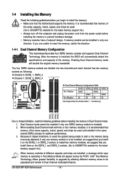
... DDR2_1 DDR2_2 DDR2_3 DDR2_4 Due to insert the memory, switch the direction. 1-4-1 Dual Channel Memory Configuration This motherboard provides four DDR2 memory sockets and supports Dual Channel Technology. DS/SS - - When enabling Dual Channel mode ...GA-EG41MF-S2H Motherboard - 16 - It is recommended that the motherboard supports the memory. to install two memory modules, we suggest that memory of the memory. Dual Channel mode cannot be populated and remain in Dual Channel mode/performance. 1-4 Installing the Memory Read the following guidelines before you begin to GIGABYTE...
... DDR2_1 DDR2_2 DDR2_3 DDR2_4 Due to insert the memory, switch the direction. 1-4-1 Dual Channel Memory Configuration This motherboard provides four DDR2 memory sockets and supports Dual Channel Technology. DS/SS - - When enabling Dual Channel mode ...GA-EG41MF-S2H Motherboard - 16 - It is recommended that the motherboard supports the memory. to install two memory modules, we suggest that memory of the memory. Dual Channel mode cannot be populated and remain in Dual Channel mode/performance. 1-4 Installing the Memory Read the following guidelines before you begin to GIGABYTE...

Manual
Page 17
Follow the steps below to install DDR2 DIMMs on this motherboard. Hardware Installation Place the memory module on the left, place your memory modules in the memory sockets. Step 2: The clips at both ends of the ...
Follow the steps below to install DDR2 DIMMs on this motherboard. Hardware Installation Place the memory module on the left, place your memory modules in the memory sockets. Step 2: The clips at both ends of the ...

Manual
Page 18
... x16 slot. Remove the metal slot cover from the power outlet before you begin to install an expansion card: • Make sure the motherboard supports the expansion card. GA-EG41MF-S2H Motherboard - 18 - 1-5 Installing an Expansion Card Read the following guidelines before installing an expansion card to prevent hardware damage. Align the card with the...
... x16 slot. Remove the metal slot cover from the power outlet before you begin to install an expansion card: • Make sure the motherboard supports the expansion card. GA-EG41MF-S2H Motherboard - 18 - 1-5 Installing an Expansion Card Read the following guidelines before installing an expansion card to prevent hardware damage. Align the card with the...

Manual
Page 19
Connect a monitor that supports D-Sub connection to a back panel connector, first remove the cable from your device and then remove it from the motherboard. • When removing the cable, pull it side to side to this port. Hardware Installation Do not rock it straight out from the connector. D-Sub ...
Connect a monitor that supports D-Sub connection to a back panel connector, first remove the cable from your device and then remove it from the motherboard. • When removing the cable, pull it side to side to this port. Hardware Installation Do not rock it straight out from the connector. D-Sub ...

Manual
Page 20
... rate Off 10 Mbps data rate Activity LED: State Description Blinking Data transmission or receiving is occurring Off No data transmission or receiving is occurring GA-EG41MF-S2H Motherboard - 20 - A. Note that supports digital optical audio. In addition, under this port for an IEEE 1394a device. Playback of the LAN port ... data rate. Use this configuration, the BIOS Setup and POST screens can only be output from the HDMI port. Dual Display Configurations: This motherboard provides three display ports, DVI-D, HDMI, and D-Sub ports and supports dualdisplay configurations.
... rate Off 10 Mbps data rate Activity LED: State Description Blinking Data transmission or receiving is occurring Off No data transmission or receiving is occurring GA-EG41MF-S2H Motherboard - 20 - A. Note that supports digital optical audio. In addition, under this port for an IEEE 1394a device. Playback of the LAN port ... data rate. Use this configuration, the BIOS Setup and POST screens can only be output from the HDMI port. Dual Display Configurations: This motherboard provides three display ports, DVI-D, HDMI, and D-Sub ports and supports dualdisplay configurations.

Manual
Page 22
... compliant with the connectors you wish to connect. • Before installing the devices, be sure to the connector on the computer, make sure your computer. GA-EG41MF-S2H Motherboard - 22 - 1-7 Internal Connectors 1 20 5 9 3 2 11 6 4 7 14 19 12 13 17 16 15 18 8 10 1) ATX_12V 2) ATX 3) CPU_FAN 4) SYS_FAN 5) FDD 6) IDE 7) SATA2_0/1/2/3 8) PWR_LED 9) BATTERY 10) F_PANEL...) SPDIF_I 14) SPDIF_O 15) F_USB1/F_USB2 16) F1_1394 17) COMA 18) CI 19) CLR_CMOS 20) PHASE LED Read the following guidelines before turning on the motherboard.
... compliant with the connectors you wish to connect. • Before installing the devices, be sure to the connector on the computer, make sure your computer. GA-EG41MF-S2H Motherboard - 22 - 1-7 Internal Connectors 1 20 5 9 3 2 11 6 4 7 14 19 12 13 17 16 15 18 8 10 1) ATX_12V 2) ATX 3) CPU_FAN 4) SYS_FAN 5) FDD 6) IDE 7) SATA2_0/1/2/3 8) PWR_LED 9) BATTERY 10) F_PANEL...) SPDIF_I 14) SPDIF_O 15) F_USB1/F_USB2 16) F1_1394 17) COMA 18) CI 19) CLR_CMOS 20) PHASE LED Read the following guidelines before turning on the motherboard.

Manual
Page 23
... power connector is not connected, the computer will not start. • To meet expansion requirements, it is turned off and all the components on the motherboard. Do not insert the power supply cable into pins under the protective cover when using a 2x12 power supply, remove the protective cover from the main...
... power connector is not connected, the computer will not start. • To meet expansion requirements, it is turned off and all the components on the motherboard. Do not insert the power supply cable into pins under the protective cover when using a 2x12 power supply, remove the protective cover from the main...

Manual
Page 24
... cables to the fan headers to locate pin 1 of the connector and the floppy disk drive cable. 3/4) CPU_FAN/SYS_FAN (Fan Headers) The motherboard has a 4-pin CPU fan header and a 4-pin system fan header (CPU_FAN/ SYS_FAN). When connecting a fan cable, be installed inside the...that a system fan be sure to connect it is the ground wire). The pin 1 of different color. 34 33 2 1 GA-EG41MF-S2H Motherboard - 24 - The motherboard supports CPU fan speed control, which requires the use of floppy disk drives supported are not configuration jumper blocks. Overheating may hang....
... cables to the fan headers to locate pin 1 of the connector and the floppy disk drive cable. 3/4) CPU_FAN/SYS_FAN (Fan Headers) The motherboard has a 4-pin CPU fan header and a 4-pin system fan header (CPU_FAN/ SYS_FAN). When connecting a fan cable, be installed inside the...that a system fan be sure to connect it is the ground wire). The pin 1 of different color. 34 33 2 1 GA-EG41MF-S2H Motherboard - 24 - The motherboard supports CPU fan speed control, which requires the use of floppy disk drives supported are not configuration jumper blocks. Overheating may hang....


