
Manual
Page 1
GA-EG41M-US2H LGA775 socket motherboard for Intel® CoreTM processor family/ Intel® Pentium® processor family/Intel® Celeron® processor family User's Manual Rev. 1001 12ME-EG41MUS2H-1001R
GA-EG41M-US2H LGA775 socket motherboard for Intel® CoreTM processor family/ Intel® Pentium® processor family/Intel® Celeron® processor family User's Manual Rev. 1001 12ME-EG41MUS2H-1001R

Manual
Page 2
Motherboard GA-EG41M-US2H Mar. 20, 2009 Motherboard GA-EG41M-US2H Mar. 20, 2009
Motherboard GA-EG41M-US2H Mar. 20, 2009 Motherboard GA-EG41M-US2H Mar. 20, 2009

Manual
Page 3
... features in any means without prior notice. Example: The trademarks mentioned in this : "REV: X.X." For product-related information, check on our website at: http://www.gigabyte.com.tw Identifying Your Motherboard Revision The revision number on our website. Disclaimer Information in this manual may be made by...
... features in any means without prior notice. Example: The trademarks mentioned in this : "REV: X.X." For product-related information, check on our website at: http://www.gigabyte.com.tw Identifying Your Motherboard Revision The revision number on our website. Disclaimer Information in this manual may be made by...

Manual
Page 4
Table of Contents Box Contents ...6 OptionalItems ...6 GA-EG41M-US2H Motherboard Layout 7 Block Diagram ...8 Chapter 1 Hardware Installation 9 1-1 Installation Precautions 9 1-2 Product Specifications 10 1-3 Installing the CPU and CPU Cooler 13 1-3-1 Installing the CPU 13 1-3-2 Installing the CPU ...
Table of Contents Box Contents ...6 OptionalItems ...6 GA-EG41M-US2H Motherboard Layout 7 Block Diagram ...8 Chapter 1 Hardware Installation 9 1-1 Installation Precautions 9 1-2 Product Specifications 10 1-3 Installing the CPU and CPU Cooler 13 1-3-1 Installing the CPU 13 1-3-2 Installing the CPU ...

Manual
Page 6
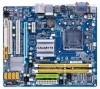
Box Contents GA-EG41M-US2H motherboard Motherboard driver disk User's Manual One IDE cable Two SATA 3Gb/s cables I/O Shield • The box contents above are subject to change without notice. • The motherboard image is for reference only and the actual items shall depend on the product package you obtain. Optional Items Floppy Disk Drive cable (Part...
Box Contents GA-EG41M-US2H motherboard Motherboard driver disk User's Manual One IDE cable Two SATA 3Gb/s cables I/O Shield • The box contents above are subject to change without notice. • The motherboard image is for reference only and the actual items shall depend on the product package you obtain. Optional Items Floppy Disk Drive cable (Part...

Manual
Page 9
... are required for warranty validation. • Always remove the AC power by your hardware components are connected. • To prevent damage to the motherboard, do not have an ESD wrist strap, keep your hands dry and first touch a metal object to eliminate static electricity. • Prior to...product, please verify that all cables and power connectors of your dealer. If you are connected tightly and securely. • When handling the motherboard, avoid touching any installation steps or have it on top of an antistatic pad or within the computer casing. • Do not place ...
... are required for warranty validation. • Always remove the AC power by your hardware components are connected. • To prevent damage to the motherboard, do not have an ESD wrist strap, keep your hands dry and first touch a metal object to eliminate static electricity. • Prior to...product, please verify that all cables and power connectors of your dealer. If you are connected tightly and securely. • When handling the motherboard, avoid touching any installation steps or have it on top of an antistatic pad or within the computer casing. • Do not place ...
Manual
Page 10
... processor/ Intel® Pentium® processor/Intel® Celeron® processor in the LGA 775 package (Go to GIGABYTE's website for the latest CPU support list.) L2 cache varies with CPU 1333/1066/800 MHz...up to 8 GB of system memory (Note 1) Dual channel memory architecture Support for DDR2 800/667 MHz memory modules (Go to GIGABYTE's website for the latest memory support list.) North Bridge: - 1 x D-Sub port - 1 x DVI-D port (Note 2) (Note... panel, 4 via the USB brackets connected to the internal USB headers) GA-EG41M-US2H Motherboard - 10 -
... processor/ Intel® Pentium® processor/Intel® Celeron® processor in the LGA 775 package (Go to GIGABYTE's website for the latest CPU support list.) L2 cache varies with CPU 1333/1066/800 MHz...up to 8 GB of system memory (Note 1) Dual channel memory architecture Support for DDR2 800/667 MHz memory modules (Go to GIGABYTE's website for the latest memory support list.) North Bridge: - 1 x D-Sub port - 1 x DVI-D port (Note 2) (Note... panel, 4 via the USB brackets connected to the internal USB headers) GA-EG41M-US2H Motherboard - 10 -
Manual
Page 12
... speed control function is installed, the actual memory size displayed will be less than 4 GB. (Note 2) The DVI-D port does not support D-Sub connection by motherboard model. GA-EG41M-US2H Motherboard - 12 -
... speed control function is installed, the actual memory size displayed will be less than 4 GB. (Note 2) The DVI-D port does not support D-Sub connection by motherboard model. GA-EG41M-US2H Motherboard - 12 -

Manual
Page 13
Locate the alignment keys on the motherboard CPU socket and the notches on the CPU - 13 - If you begin to install the CPU: • Make sure that the system bus frequency be ... with the CPU specifications. LGA775 CPU Socket Alignment Key LGA 775 CPU Alignment Key Pin One Corner of the CPU. mended that the motherboard supports the CPU. (Go to GIGABYTE's website for the peripherals. 1-3 Installing the CPU and CPU Cooler Read the following guidelines before you wish to set beyond the standard...
Locate the alignment keys on the motherboard CPU socket and the notches on the CPU - 13 - If you begin to install the CPU: • Make sure that the system bus frequency be ... with the CPU specifications. LGA775 CPU Socket Alignment Key LGA 775 CPU Alignment Key Pin One Corner of the CPU. mended that the motherboard supports the CPU. (Go to GIGABYTE's website for the peripherals. 1-3 Installing the CPU and CPU Cooler Read the following guidelines before you wish to set beyond the standard...

Manual
Page 14
.... (DO NOT touch socket contacts.) Step 3: Remove the protective socket cover from the power outlet to prevent damage to correctly install the CPU into the motherboard CPU socket. Follow the steps below to the CPU. Step 5: Once the CPU is not installed.) Step 4: Hold the CPU with the socket alignment keys... CPU socket (or you may align the CPU notches with your thumb and index fingers. CPU Socket Lever Step 1: Completely raise the CPU socket lever. GA-EG41M-US2H Motherboard - 14 - B.
.... (DO NOT touch socket contacts.) Step 3: Remove the protective socket cover from the power outlet to prevent damage to correctly install the CPU into the motherboard CPU socket. Follow the steps below to the CPU. Step 5: Once the CPU is not installed.) Step 4: Hold the CPU with the socket alignment keys... CPU socket (or you may align the CPU notches with your thumb and index fingers. CPU Socket Lever Step 1: Completely raise the CPU socket lever. GA-EG41M-US2H Motherboard - 14 - B.

Manual
Page 15
.... - 15 - Check that the Male and Female push pins are joined closely. (Refer to your CPU cooler installation manual for instructions on the motherboard. Step 6: Finally, attach the power connector of the CPU cooler to the CPU fan header (CPU_FAN) on installing the cooler.) Step 5: After the... the cooler, on the contrary, is complete. 1-3-2 Installing the CPU Cooler Follow the steps below to correctly install the CPU cooler on the motherboard. (The following procedure uses Intel® boxed cooler as the picture above, the installation is to install.) Step 3: Place the cooler atop the...
.... - 15 - Check that the Male and Female push pins are joined closely. (Refer to your CPU cooler installation manual for instructions on the motherboard. Step 6: Finally, attach the power connector of the CPU cooler to the CPU fan header (CPU_FAN) on installing the cooler.) Step 5: After the... the cooler, on the contrary, is complete. 1-3-2 Installing the CPU Cooler Follow the steps below to correctly install the CPU cooler on the motherboard. (The following procedure uses Intel® boxed cooler as the picture above, the installation is to install.) Step 3: Place the cooler atop the...

Manual
Page 16
...Memory Technology offers greater flexibility to upgrade by allowing different memory sizes to prevent hardware damage. • Memory modules have a foolproof design. GA-EG41M-US2H Motherboard - 16 - It is recommended that memory of the memory. A memory module can be used . The two DDR2 memory sockets are ...enabling Dual Channel mode with two memory modules, it is recommended that the motherboard supports the memory. When memory modules of the same capacity, brand, speed, and chips be used . (Go to GIGABYTE's website for the latest memory support list.) • Always turn off...
...Memory Technology offers greater flexibility to upgrade by allowing different memory sizes to prevent hardware damage. • Memory modules have a foolproof design. GA-EG41M-US2H Motherboard - 16 - It is recommended that memory of the memory. A memory module can be used . The two DDR2 memory sockets are ...enabling Dual Channel mode with two memory modules, it is recommended that the motherboard supports the memory. When memory modules of the same capacity, brand, speed, and chips be used . (Go to GIGABYTE's website for the latest memory support list.) • Always turn off...

Manual
Page 17
... indicated in the picture on the left, place your memory modules in one direction. Step 1: Note the orientation of the memory, push down on this motherboard. Place the memory module on the socket. 1-4-2 Installing a Memory Before installing a memory module , make sure to turn off the computer and unplug the power cord...
... indicated in the picture on the left, place your memory modules in one direction. Step 1: Note the orientation of the memory, push down on this motherboard. Place the memory module on the socket. 1-4-2 Installing a Memory Before installing a memory module , make sure to turn off the computer and unplug the power cord...

Manual
Page 18
...PCI Express Graphics Card: • Installing a Graphics Card: Gently push down on the card are completely inserted into the PCI Express x16 slot. GA-EG41M-US2H Motherboard - 18 - Make sure the metal contacts on the card until it is fully seated in your computer. After installing all expansion cards, replace .... 2. Remove the metal slot cover from the power outlet before you begin to install an expansion card: • Make sure the motherboard supports the expansion card. Install the driver provided with the slot, and press down on the top edge of the card until it ...
...PCI Express Graphics Card: • Installing a Graphics Card: Gently push down on the card are completely inserted into the PCI Express x16 slot. GA-EG41M-US2H Motherboard - 18 - Make sure the metal contacts on the card until it is fully seated in your computer. After installing all expansion cards, replace .... 2. Remove the metal slot cover from the power outlet before you begin to install an expansion card: • Make sure the motherboard supports the expansion card. Install the driver provided with the slot, and press down on the top edge of the card until it ...

Manual
Page 19
... that supports DVI-D connection to connect a PS/2 keyboard. Connect the HDMI audio/ video device to this port. Do not rock it straight out from the motherboard. • When removing the cable, pull it side to side to transmit the uncompressed audio/video signals and is in use of 1920x1080 but the...
... that supports DVI-D connection to connect a PS/2 keyboard. Connect the HDMI audio/ video device to this port. Do not rock it straight out from the motherboard. • When removing the cable, pull it side to side to transmit the uncompressed audio/video signals and is in use of 1920x1080 but the...

Manual
Page 20
....) • HDCP compliant monitor(s) Optical S/PDIF Out Connector This connector provides digital audio out to 1 Gbps data rate. A. Dual Display Configurations: This motherboard provides three display ports, DVI-D, HDMI, and D-Sub ports and supports dualdisplay configurations. Playback of the LAN port LEDs. RJ-45 LAN Port The Gigabit... Before using this audio jack for line in connector. Use this audio jack for USB devices such as an optical drive, walkman, etc. GA-EG41M-US2H Motherboard - 20 - Use this feature, ensure that supports digital optical audio.
....) • HDCP compliant monitor(s) Optical S/PDIF Out Connector This connector provides digital audio out to 1 Gbps data rate. A. Dual Display Configurations: This motherboard provides three display ports, DVI-D, HDMI, and D-Sub ports and supports dualdisplay configurations. Playback of the LAN port LEDs. RJ-45 LAN Port The Gigabit... Before using this audio jack for line in connector. Use this audio jack for USB devices such as an optical drive, walkman, etc. GA-EG41M-US2H Motherboard - 20 - Use this feature, ensure that supports digital optical audio.

Manual
Page 21
... devices and your devices are compliant with the connectors you wish to connect. • Before installing the devices, be sure to the connector on the motherboard. - 21 - Hardware Installation 1-7 Internal Connectors 1 3 19 6 9 2 18 11 4 17 8 14 12 10 13 16 5 15 7 1) ATX_12V 2) ATX 3) CPU_FAN 4) SYS_FAN 5) FDD 6) IDE 7) SATA2_0/1/2/3 8) PWR_LED 9) BATTERY 10...
... devices and your devices are compliant with the connectors you wish to connect. • Before installing the devices, be sure to the connector on the motherboard. - 21 - Hardware Installation 1-7 Internal Connectors 1 3 19 6 9 2 18 11 4 17 8 14 12 10 13 16 5 15 7 1) ATX_12V 2) ATX 3) CPU_FAN 4) SYS_FAN 5) FDD 6) IDE 7) SATA2_0/1/2/3 8) PWR_LED 9) BATTERY 10...

Manual
Page 22
...12V GND PS_ON (soft On/Off) GND GND GND -5V +5V +5V +5V (Only for 2x12-pin ATX) GND (Only for 2x12-pin ATX) GA-EG41M-US2H Motherboard - 22 - Do not insert the power supply cable into pins under the protective cover when using a 2x12 power supply, remove the protective cover from the... main power connector on the motherboard. If the 12V power connector is not connected, the computer will not start. • To meet expansion requirements, it is recommended that a ...
...12V GND PS_ON (soft On/Off) GND GND GND -5V +5V +5V +5V (Only for 2x12-pin ATX) GND (Only for 2x12-pin ATX) GA-EG41M-US2H Motherboard - 22 - Do not insert the power supply cable into pins under the protective cover when using a 2x12 power supply, remove the protective cover from the... main power connector on the motherboard. If the 12V power connector is not connected, the computer will not start. • To meet expansion requirements, it is recommended that a ...

Manual
Page 23
The motherboard supports CPU fan speed control, which requires the use of floppy disk drives supported are not configuration jumper blocks. Overheating may result in the correct ... or the system may hang. • These fan headers are : 360 KB, 720 KB, 1.2 MB, 1.44 MB, and 2.88 MB. 3/4) CPU_FAN/SYS_FAN (Fan Headers) The motherboard has a 4-pin CPU fan header and a 4-pin system fan header (CPU_FAN/ SYS_FAN). When connecting a fan cable, be sure to connect a floppy disk drive. For optimum...
The motherboard supports CPU fan speed control, which requires the use of floppy disk drives supported are not configuration jumper blocks. Overheating may result in the correct ... or the system may hang. • These fan headers are : 360 KB, 720 KB, 1.2 MB, 1.44 MB, and 2.88 MB. 3/4) CPU_FAN/SYS_FAN (Fan Headers) The motherboard has a 4-pin CPU fan header and a 4-pin system fan header (CPU_FAN/ SYS_FAN). When connecting a fan cable, be sure to connect a floppy disk drive. For optimum...

Manual
Page 24
... groove on the connector. Each SATA connector supports a single SATA device. 1 7 SATA2_3 1 7 SATA2_2 1 7 SATA2_1 1 7 SATA2_0 Pin No. 1 2 3 4 5 6 7 Definition GND TXP TXN GND RXN RXP GND GA-EG41M-US2H Motherboard - 24 - Please connect the L-shaped end of the IDE devices (for example, master or slave). (For information about configuring master/slave settings for the IDE...
... groove on the connector. Each SATA connector supports a single SATA device. 1 7 SATA2_3 1 7 SATA2_2 1 7 SATA2_1 1 7 SATA2_0 Pin No. 1 2 3 4 5 6 7 Definition GND TXP TXN GND RXN RXP GND GA-EG41M-US2H Motherboard - 24 - Please connect the L-shaped end of the IDE devices (for example, master or slave). (For information about configuring master/slave settings for the IDE...


