
Manual
Page 2
Motherboard GA-D510UD Feb. 5, 2010 Motherboard GA-D510UD Feb. 5, 2010
Motherboard GA-D510UD Feb. 5, 2010 Motherboard GA-D510UD Feb. 5, 2010

Manual
Page 3
.... For product-related information, check on our website at: http://www.gigabyte.com.tw Identifying Your Motherboard Revision The revision number on our website. All rights reserved. No part of GIGABYTE. The trademarks mentioned in any means without prior notice. Example: Changes ... © 2010 GIGA-BYTE TECHNOLOGY CO., LTD. Check your motherboard looks like this manual may be made by any form or by GIGABYTE without GIGABYTE's prior written permission. For example, "REV: 1.0" means the revision of the motherboard is the property of this manual may be reproduced, copied, ...
.... For product-related information, check on our website at: http://www.gigabyte.com.tw Identifying Your Motherboard Revision The revision number on our website. All rights reserved. No part of GIGABYTE. The trademarks mentioned in any means without prior notice. Example: Changes ... © 2010 GIGA-BYTE TECHNOLOGY CO., LTD. Check your motherboard looks like this manual may be made by any form or by GIGABYTE without GIGABYTE's prior written permission. For example, "REV: 1.0" means the revision of the motherboard is the property of this manual may be reproduced, copied, ...

Manual
Page 4
Table of Contents Box Contents...6 Optional Items...6 GA-D510UD Motherboard Layout 7 GA-D510UD Motherboard Block Diagram 8 Chapter 1 Hardware Installation 9 1-1 Installation Precautions 9 1-2 Product Specifications 10 1-3 Installing the Memory 12 1-4 Back Panel Connectors 13 1-5 Internal Connectors 15 Chapter 2 BIOS Setup 23 2-1 ...
Table of Contents Box Contents...6 Optional Items...6 GA-D510UD Motherboard Layout 7 GA-D510UD Motherboard Block Diagram 8 Chapter 1 Hardware Installation 9 1-1 Installation Precautions 9 1-2 Product Specifications 10 1-3 Installing the Memory 12 1-4 Back Panel Connectors 13 1-5 Internal Connectors 15 Chapter 2 BIOS Setup 23 2-1 ...

Manual
Page 6
Optional Items 2-port USB 2.0 bracket (Part No. 12CR1-1UB030-5*R) 2-port SATA power cable (Part No. 12CF1-2SERPW-0*R) - 6 - The box contents are for reference only. Box Contents GA-D510UD motherboard Motherboard driver disk User's Manual One IDE cable One SATA 3Gb/s cable I/O Shield • The box contents above are subject to change without notice. • The motherboard image is for reference only and the actual items shall depend on the product package you obtain.
Optional Items 2-port USB 2.0 bracket (Part No. 12CR1-1UB030-5*R) 2-port SATA power cable (Part No. 12CF1-2SERPW-0*R) - 6 - The box contents are for reference only. Box Contents GA-D510UD motherboard Motherboard driver disk User's Manual One IDE cable One SATA 3Gb/s cable I/O Shield • The box contents above are subject to change without notice. • The motherboard image is for reference only and the actual items shall depend on the product package you obtain.

Manual
Page 8
GA-D510UD Motherboard Block Diagram D-Sub Intel® Atom™ Processor CPU CLK+/- (133 MHz) DDR2 800/667 MHz Memory DMI Interface LAN RJ45 PCIe CLK (100 MHz) RTL8111D x1 PCI Express Bus Intel® NM10 x1 2 SATA 3Gb/s ATA-133/100/66/33 IDE Channel GIGABYTE SATA2 PCI Bus Dual BIOS 2 SATA 3Gb/s 8 USB 2.0/1.1 IT8720 LPC Bus LPT Port COM Ports CODEC PS/2 KB/Mouse MIC (Center/Subwoofer Speaker Out) Line-Out (Front Speaker Out) Line-In (Rear Speaker Out) 1 PCI PCI CLK (33 MHz) - 8 -
GA-D510UD Motherboard Block Diagram D-Sub Intel® Atom™ Processor CPU CLK+/- (133 MHz) DDR2 800/667 MHz Memory DMI Interface LAN RJ45 PCIe CLK (100 MHz) RTL8111D x1 PCI Express Bus Intel® NM10 x1 2 SATA 3Gb/s ATA-133/100/66/33 IDE Channel GIGABYTE SATA2 PCI Bus Dual BIOS 2 SATA 3Gb/s 8 USB 2.0/1.1 IT8720 LPC Bus LPT Port COM Ports CODEC PS/2 KB/Mouse MIC (Center/Subwoofer Speaker Out) Line-Out (Front Speaker Out) Line-In (Rear Speaker Out) 1 PCI PCI CLK (33 MHz) - 8 -
Manual
Page 9
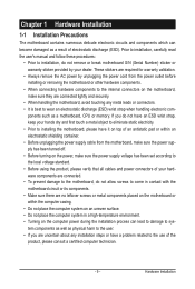
...system on an uneven surface. • Do not place the computer system in a high-temperature environment. • Turning on the motherboard, make sure the power supply voltage has been set according to wear an electrostatic discharge (ESD) wrist strap when handling electronic com-...within an electrostatic shielding container. • Before unplugging the power supply cable from the power outlet before installing or removing the motherboard or other hardware components. • When connecting hardware components to the internal connectors on the computer power during the installation ...
...system on an uneven surface. • Do not place the computer system in a high-temperature environment. • Turning on the motherboard, make sure the power supply voltage has been set according to wear an electrostatic discharge (ESD) wrist strap when handling electronic com-...within an electrostatic shielding container. • Before unplugging the power supply cable from the power outlet before installing or removing the motherboard or other hardware components. • When connecting hardware components to the internal connectors on the computer power during the installation ...

Manual
Page 11
... an HD front panel audio module and enable the multi-channel audio feature through the audio driver. (Note 4) Available functions in EasyTune may differ by motherboard model. - 11 - Hardware Installation
... an HD front panel audio module and enable the multi-channel audio feature through the audio driver. (Note 4) Available functions in EasyTune may differ by motherboard model. - 11 - Hardware Installation

Manual
Page 12
...install your fingers on the top edge of the memory, push down on the memory and insert it can be used. (Go to GIGABYTE's website for the latest memory support list.) • Always turn off the computer and unplug the power cord from the power outlet before...DDR2 memory module has a notch, so it vertically into place when the memory module is recommended that the motherboard supports the memory. Hardware Installation - 12 - Place the memory module on this motherboard. A memory module can only fit in one direction. 1-3 Installing the Memory Read the following guidelines before ...
...install your fingers on the top edge of the memory, push down on the memory and insert it can be used. (Go to GIGABYTE's website for the latest memory support list.) • Always turn off the computer and unplug the power cord from the power outlet before...DDR2 memory module has a notch, so it vertically into place when the memory module is recommended that the motherboard supports the memory. Hardware Installation - 12 - Place the memory module on this motherboard. A memory module can only fit in one direction. 1-3 Installing the Memory Read the following guidelines before ...

Manual
Page 13
... USB devices such as a printer, scanner and etc. USB 2.0/1.1 Port The USB port supports the USB 2.0/1.1 specification. Do not rock it straight out from the motherboard. • When removing the cable, pull it side to side to connect a PS/2 keyboard. The parallel port is occurring LAN Port Off 10 Mbps data...
... USB devices such as a printer, scanner and etc. USB 2.0/1.1 Port The USB port supports the USB 2.0/1.1 specification. Do not rock it straight out from the motherboard. • When removing the cable, pull it side to side to connect a PS/2 keyboard. The parallel port is occurring LAN Port Off 10 Mbps data...

Manual
Page 15
... 4) SYS_FAN 5) IDE 6) SATA2_0/1 7) GSATA2_0/1 8) PWR_LED 9) BAT 10) F_PANEL 11) F_AUDIO 12) F_USB1/F_USB2 13) COMB 14) CI Read the following guidelines before turning on the motherboard. - 15 - Unplug the power cord from the power outlet to prevent damage to the devices. • After installing the device and before connecting external devices...
... 4) SYS_FAN 5) IDE 6) SATA2_0/1 7) GSATA2_0/1 8) PWR_LED 9) BAT 10) F_PANEL 11) F_AUDIO 12) F_USB1/F_USB2 13) COMB 14) CI Read the following guidelines before turning on the motherboard. - 15 - Unplug the power cord from the power outlet to prevent damage to the devices. • After installing the device and before connecting external devices...
Manual
Page 16
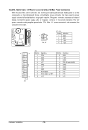
... On/Off) GND GND GND -5V +5V +5V Hardware Installation - 16 - If the 12V power connector is turned off and all the components on the motherboard. The 12V power connector mainly supplies power to the power connector in the correct orientation. Connect the power supply cable to the CPU. The power...
... On/Off) GND GND GND -5V +5V +5V Hardware Installation - 16 - If the 12V power connector is turned off and all the components on the motherboard. The 12V power connector mainly supplies power to the power connector in the correct orientation. Connect the power supply cable to the CPU. The power...

Manual
Page 17
... correct orientation (the black connector wire is the ground wire). Before attaching the IDE cable, locate the foolproof groove on the connector. Hardware Installation The motherboard supports CPU fan speed control, which requires the use of the IDE devices (for example, master or slave). (For information about configuring master/slave settings... Sense 5) IDE (IDE Connector) The IDE connector supports up to the role of a CPU fan with fan speed control design. 3/4) CPU_FAN/SYS_FAN (Fan Headers) The motherboard has a 3-pin CPU fan header (CPU_FAN) and a 3-pin (SYS_FAN) system fan header.
... correct orientation (the black connector wire is the ground wire). Before attaching the IDE cable, locate the foolproof groove on the connector. Hardware Installation The motherboard supports CPU fan speed control, which requires the use of the IDE devices (for example, master or slave). (For information about configuring master/slave settings... Sense 5) IDE (IDE Connector) The IDE connector supports up to the role of a CPU fan with fan speed control design. 3/4) CPU_FAN/SYS_FAN (Fan Headers) The motherboard has a 3-pin CPU fan header (CPU_FAN) and a 3-pin (SYS_FAN) system fan header.

Manual
Page 21
Incorrect connection between the module connector and the motherboard header will be sure to turn off your computer and unplug the power cord from the power outlet to prevent damage to installing the USB ... High Definition audio (HD) and AC'97 audio. For information about connecting the front panel audio module that has separated connectors on both of the motherboard header. For purchasing the optional USB bracket, please contact the local dealer. 10 9 2 1 Pin No. 1 2 3 4 5 6 7 8 9 10 Definition Power (5V) Power (5V) USB DXUSB DYUSB DX...
Incorrect connection between the module connector and the motherboard header will be sure to turn off your computer and unplug the power cord from the power outlet to prevent damage to installing the USB ... High Definition audio (HD) and AC'97 audio. For information about connecting the front panel audio module that has separated connectors on both of the motherboard header. For purchasing the optional USB bracket, please contact the local dealer. 10 9 2 1 Pin No. 1 2 3 4 5 6 7 8 9 10 Definition Power (5V) Power (5V) USB DXUSB DYUSB DX...

Manual
Page 22
This function requires a chassis with chassis intrusion detection design. Definition 10 9 1 NDCD- 2 NSIN 3 NSOUT 4 NDTR- 21 5 GND 6 NDSR- 7 NRTS- 8 NCTS- 9 NRI- 10 No Pin 14) CI (Chassis Intrusion Header) This motherboard provides a chassis detection feature that detects if the chassis cover has been removed. Pin No. Pin No. 13) COMB (Serial Port Header) The COM header can provide one serial port via an optional COM port cable. Definition 1 Signal 1 2 GND Hardware Installation - 22 - For purchasing the optional COM port cable, please contact the local dealer.
This function requires a chassis with chassis intrusion detection design. Definition 10 9 1 NDCD- 2 NSIN 3 NSOUT 4 NDTR- 21 5 GND 6 NDSR- 7 NRTS- 8 NCTS- 9 NRI- 10 No Pin 14) CI (Chassis Intrusion Header) This motherboard provides a chassis detection feature that detects if the chassis cover has been removed. Pin No. Pin No. 13) COMB (Serial Port Header) The COM header can provide one serial port via an optional COM port cable. Definition 1 Signal 1 2 GND Hardware Installation - 22 - For purchasing the optional COM port cable, please contact the local dealer.

Manual
Page 23
... Setup program that searches and downloads the latest version of BIOS from the Internet and updates the BIOS. To upgrade the BIOS, use either the GIGABYTE Q-Flash or @BIOS utility. • Q-Flash allows the user to quickly and easily upgrade or back up BIOS without entering the operating system...in the CMOS. Inadequate BIOS flashing may result in Chapter 1 for the beep codes description. • It is turned off, the battery on the motherboard. When the power is recommended that you can press + in system malfunction. • BIOS will emit a beep code during system startup, saving ...
... Setup program that searches and downloads the latest version of BIOS from the Internet and updates the BIOS. To upgrade the BIOS, use either the GIGABYTE Q-Flash or @BIOS utility. • Q-Flash allows the user to quickly and easily upgrade or back up BIOS without entering the operating system...in the CMOS. Inadequate BIOS flashing may result in Chapter 1 for the beep codes description. • It is turned off, the battery on the motherboard. When the power is recommended that you can press + in system malfunction. • BIOS will emit a beep code during system startup, saving ...

Manual
Page 24
... POST. After system restart, the device boot order will directly boot from the device configured in Boot Menu is effective for subsequent access to accept. D510UD E26c . . . . : BIOS Setup : XpressRecovery2 : Boot Menu : Qflash 12/29/2009-PINE-7A89SG02C-00 Function Keys Function Keys: : BIOS SETUP Press the ... change the first boot device setting as needed. : Q-FLASH Press the key to enter BIOS Setup first. To exit Boot Menu, press . Motherboard Model BIOS Version Award Modular BIOS v6.00PG, An Energy Star Ally Copyright (C) 1984-2010, Award Software, Inc. BIOS Setup - 24 -
... POST. After system restart, the device boot order will directly boot from the device configured in Boot Menu is effective for subsequent access to accept. D510UD E26c . . . . : BIOS Setup : XpressRecovery2 : Boot Menu : Qflash 12/29/2009-PINE-7A89SG02C-00 Function Keys Function Keys: : BIOS SETUP Press the ... change the first boot device setting as needed. : Q-FLASH Press the key to enter BIOS Setup first. To exit Boot Menu, press . Motherboard Model BIOS Version Award Modular BIOS v6.00PG, An Energy Star Ally Copyright (C) 1984-2010, Award Software, Inc. BIOS Setup - 24 -

Manual
Page 33
...; Move Enter: Select F5: Previous Values +/-/PU/PD: Value F10: Save F6: Fail-Safe Defaults ESC: Exit F1: General Help F7: Optimized Defaults This motherboard incorporates cable diagnostic feature designed to detect the status of using the onboard audio, set this item to Disabled. This feature will dynamically detect if...
...; Move Enter: Select F5: Previous Values +/-/PU/PD: Value F10: Save F6: Fail-Safe Defaults ESC: Exit F1: General Help F7: Optimized Defaults This motherboard incorporates cable diagnostic feature designed to detect the status of using the onboard audio, set this item to Disabled. This feature will dynamically detect if...

Manual
Page 34
... RAID/IDE Enables RAID for the SATA controller and configures the SATA controller to IDE mode. (Default) AHCI Configures the SATA controller to the motherboard, the Status fields of all four pairs of 10/100/1000 Mbps in the figure above. When LAN Cable Is Functioning Normally... If no LAN... and the length shown is activated. Note: Part 4-5 and Part 7-8 are not used in MS-DOS mode; the IDE controller still operates in the GIGABYTE SATA2 chip or configures the SATA controller to a Gigabit hub or a 10/100 Mbps hub, the following message will operate at a speed of the ...
... RAID/IDE Enables RAID for the SATA controller and configures the SATA controller to IDE mode. (Default) AHCI Configures the SATA controller to the motherboard, the Status fields of all four pairs of 10/100/1000 Mbps in the figure above. When LAN Cable Is Functioning Normally... If no LAN... and the length shown is activated. Note: Part 4-5 and Part 7-8 are not used in MS-DOS mode; the IDE controller still operates in the GIGABYTE SATA2 chip or configures the SATA controller to a Gigabit hub or a 10/100 Mbps hub, the following message will operate at a speed of the ...

Manual
Page 39
... status of previous chassis intrusion status. To clear the chassis intrusion status record, set Reset Case Open Status to Enabled, save the settings to the motherboard CI header. Current Voltage(V) Vcore/DDR18V/+3.3V/+12V Displays the current system voltages. 2-9 PC Health Status CMOS Setup Utility-Copyright (C) 1984-2010 Award Software PC...
... status of previous chassis intrusion status. To clear the chassis intrusion status record, set Reset Case Open Status to Enabled, save the settings to the motherboard CI header. Current Voltage(V) Vcore/DDR18V/+3.3V/+12V Displays the current system voltages. 2-9 PC Health Status CMOS Setup Utility-Copyright (C) 1984-2010 Award Software PC...

Manual
Page 40
... - 40 - In case system instability occurs, you may try to load Fail-Safe defaults, which are the safest and most stable BIOS settings for the motherboard. 2-11 Load Optimized Defaults CMOS Setup Utility-Copyright (C) 1984-2010 Award Software MB Intelligent Tweaker(M.I .T.) Load Fail-Safe Defaults Standard CMOS Features Load...
... - 40 - In case system instability occurs, you may try to load Fail-Safe defaults, which are the safest and most stable BIOS settings for the motherboard. 2-11 Load Optimized Defaults CMOS Setup Utility-Copyright (C) 1984-2010 Award Software MB Intelligent Tweaker(M.I .T.) Load Fail-Safe Defaults Standard CMOS Features Load...


