
Manual
Page 3
...Changes to the specifications and features in this product, GIGABYTE provides the following types of GIGABYTE. All rights reserved. For product-related information, check on our website at: http://www.gigabyte.com Identifying Your Motherboard Revision The revision number on our website. For ...example, "REV: 1.0" means the revision of the motherboard is the property of documentations: For detailed product information,...
...Changes to the specifications and features in this product, GIGABYTE provides the following types of GIGABYTE. All rights reserved. For product-related information, check on our website at: http://www.gigabyte.com Identifying Your Motherboard Revision The revision number on our website. For ...example, "REV: 1.0" means the revision of the motherboard is the property of documentations: For detailed product information,...

Manual
Page 4
Table of Contents Box Contents...6 Optional Items...6 GA-D525TUD/GA-D425TUD Motherboard Layout 7 GA-D525TUD/GA-D425TUD Motherboard Block Diagram 8 Chapter 1 Hardware Installation 9 1-1 Installation Precautions 9 1-2 Product Specifications 10 1-3 Installing the Memory 12 1-4 Back Panel Connectors 13 1-5 Internal Connectors 15 Chapter 2 BIOS Setup 23 2-1 ...
Table of Contents Box Contents...6 Optional Items...6 GA-D525TUD/GA-D425TUD Motherboard Layout 7 GA-D525TUD/GA-D425TUD Motherboard Block Diagram 8 Chapter 1 Hardware Installation 9 1-1 Installation Precautions 9 1-2 Product Specifications 10 1-3 Installing the Memory 12 1-4 Back Panel Connectors 13 1-5 Internal Connectors 15 Chapter 2 BIOS Setup 23 2-1 ...

Manual
Page 6
Optional Items 2-port USB 2.0 bracket (Part No. 12CR1-1UB030-5*R) 2-port SATA power cable (Part No. 12CF1-2SERPW-0*R) COM port cable (Part No. 12CF1-1CM001-3*R) - 6 - The box contents are for reference only. Box Contents GA-D525TUD or GA-D425TUD motherboard Motherboard driver disk User's Manual One IDE cable One SATA cable I/O Shield • The box contents above are subject to change without notice. • The motherboard image is for reference only and the actual items shall depend on the product package you obtain.
Optional Items 2-port USB 2.0 bracket (Part No. 12CR1-1UB030-5*R) 2-port SATA power cable (Part No. 12CF1-2SERPW-0*R) COM port cable (Part No. 12CF1-1CM001-3*R) - 6 - The box contents are for reference only. Box Contents GA-D525TUD or GA-D425TUD motherboard Motherboard driver disk User's Manual One IDE cable One SATA cable I/O Shield • The box contents above are subject to change without notice. • The motherboard image is for reference only and the actual items shall depend on the product package you obtain.
Manual
Page 7
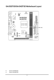
GA-D525TUD/GA-D425TUD Motherboard Layout COM KB_MS iTE IT8720 CI ATX_12V CPU_FAN GA-D525TUD/ GA-D425TUD LPT COMB VGA BAT R_USB Realtek RTL8111E USB_LAN AUDIO F_AUDIO CODEC Intel® Atom™ D525j Intel® Atom™ D425k F_USB1 F_USB2 Intel® NM10 SATA2_0 SATA2_1 B_BIOS M_BIOS PCI DDR3_1 DDR3_2 PWR_LED GSATA2_1GSATA2_0 SYS_FAN IDE ATX F_PANEL GIGABYTE SATA2 j Only for GA-D425TUD. - 7 - k Only for GA-D525TUD.
GA-D525TUD/GA-D425TUD Motherboard Layout COM KB_MS iTE IT8720 CI ATX_12V CPU_FAN GA-D525TUD/ GA-D425TUD LPT COMB VGA BAT R_USB Realtek RTL8111E USB_LAN AUDIO F_AUDIO CODEC Intel® Atom™ D525j Intel® Atom™ D425k F_USB1 F_USB2 Intel® NM10 SATA2_0 SATA2_1 B_BIOS M_BIOS PCI DDR3_1 DDR3_2 PWR_LED GSATA2_1GSATA2_0 SYS_FAN IDE ATX F_PANEL GIGABYTE SATA2 j Only for GA-D425TUD. - 7 - k Only for GA-D525TUD.

Manual
Page 8
GA-D525TUD/GA-D425TUD Motherboard Block Diagram D-Sub Intel® Atom™ CPU CPU CLK+/- (200 MHz) DDR3 800 MHz Memory DMI Interface LAN RJ45 PCIe CLK (100 MHz) Realtek RTL8111E x1 PCI Express Bus Intel® NM10 x1 2 SATA 3Gb/s ATA-133/100/66/33 IDE Channel GIGABYTE SATA2 PCI Bus Dual BIOS 2 SATA 3Gb/s 8 USB 2.0/1.1 iTE LPC Bus IT8720 LPT Port COM Ports CODEC PS/2 KB/Mouse MIC (Center/Subwoofer Speaker Out) Line-Out (Front Speaker Out) Line-In (Rear Speaker Out) 1 PCI PCI CLK (33 MHz) - 8 -
GA-D525TUD/GA-D425TUD Motherboard Block Diagram D-Sub Intel® Atom™ CPU CPU CLK+/- (200 MHz) DDR3 800 MHz Memory DMI Interface LAN RJ45 PCIe CLK (100 MHz) Realtek RTL8111E x1 PCI Express Bus Intel® NM10 x1 2 SATA 3Gb/s ATA-133/100/66/33 IDE Channel GIGABYTE SATA2 PCI Bus Dual BIOS 2 SATA 3Gb/s 8 USB 2.0/1.1 iTE LPC Bus IT8720 LPT Port COM Ports CODEC PS/2 KB/Mouse MIC (Center/Subwoofer Speaker Out) Line-Out (Front Speaker Out) Line-In (Rear Speaker Out) 1 PCI PCI CLK (33 MHz) - 8 -

Manual
Page 9
...ponents such as a result of the product, please consult a certified computer technician. - 9 - Chapter 1 Hardware Installation 1-1 Installation Precautions The motherboard contains numerous delicate electronic circuits and components which can lead to damage to system components as well as physical harm to the user. • ...top of an antistatic pad or within an electrostatic shielding container. • Before unplugging the power supply cable from the motherboard, make sure the power supply has been turned off. • Before turning on the computer power during the installation process ...
...ponents such as a result of the product, please consult a certified computer technician. - 9 - Chapter 1 Hardware Installation 1-1 Installation Precautions The motherboard contains numerous delicate electronic circuits and components which can lead to damage to system components as well as physical harm to the user. • ...top of an antistatic pad or within an electrostatic shielding container. • Before unplugging the power supply cable from the motherboard, make sure the power supply has been turned off. • Before turning on the computer power during the installation process ...

Manual
Page 11
... an HD front panel audio module and enable the multi-channel audio feature through the audio driver. (Note 4) Available functions in EasyTune may differ by motherboard model. - 11 - Hardware Installation
... an HD front panel audio module and enable the multi-channel audio feature through the audio driver. (Note 4) Available functions in EasyTune may differ by motherboard model. - 11 - Hardware Installation
Manual
Page 12
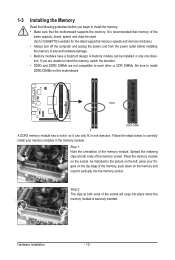
.... Hardware Installation - 12 - Notch DDR3 DIMM A DDR3 memory module has a notch, so it vertically into place when the memory module is recommended that the motherboard supports the memory. Place the memory module on the memory and insert it can be installed in the picture on the top edge of the... same capacity, brand, speed, and chips be used. (Go to GIGABYTE's website for the latest supported memory speeds and memory modules.) • Always turn off the computer and unplug the power cord from the power outlet...
.... Hardware Installation - 12 - Notch DDR3 DIMM A DDR3 memory module has a notch, so it vertically into place when the memory module is recommended that the motherboard supports the memory. Place the memory module on the memory and insert it can be installed in the picture on the top edge of the... same capacity, brand, speed, and chips be used. (Go to GIGABYTE's website for the latest supported memory speeds and memory modules.) • Always turn off the computer and unplug the power cord from the power outlet...

Manual
Page 13
... data rate • When removing the cable connected to a back panel connector, first remove the cable from your device and then remove it from the motherboard. • When removing the cable, pull it side to side to connect devices such as a mouse, modem or other peripherals. D-Sub Port The D-Sub port...
... data rate • When removing the cable connected to a back panel connector, first remove the cable from your device and then remove it from the motherboard. • When removing the cable, pull it side to side to connect devices such as a mouse, modem or other peripherals. D-Sub Port The D-Sub port...

Manual
Page 15
... 4) SYS_FAN 5) IDE 6) SATA2_0/1 7) GSATA2_0/1 8) PWR_LED 9) BAT 10) F_PANEL 11) F_AUDIO 12) F_USB1/F_USB2 13) COMB 14) CI Read the following guidelines before turning on the motherboard. - 15 - Hardware Installation Unplug the power cord from the power outlet to prevent damage to the devices. • After installing the device and before connecting...
... 4) SYS_FAN 5) IDE 6) SATA2_0/1 7) GSATA2_0/1 8) PWR_LED 9) BAT 10) F_PANEL 11) F_AUDIO 12) F_USB1/F_USB2 13) COMB 14) CI Read the following guidelines before turning on the motherboard. - 15 - Hardware Installation Unplug the power cord from the power outlet to prevent damage to the devices. • After installing the device and before connecting...

Manual
Page 16
... mainly supplies power to the power connector in the correct orientation. If the 12V power connector is turned off and all the components on the motherboard. 1/2) ATX_12V/ATX (2x2 12V Power Connector and 2x10 Main Power Connector) With the use of the power connector, the power supply can supply enough stable...
... mainly supplies power to the power connector in the correct orientation. If the 12V power connector is turned off and all the components on the motherboard. 1/2) ATX_12V/ATX (2x2 12V Power Connector and 2x10 Main Power Connector) With the use of the power connector, the power supply can supply enough stable...
Manual
Page 17
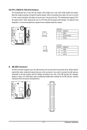
The motherboard supports CPU fan speed control, which requires the use of the IDE devices (for example, master or slave). (For information about configuring master/slave settings ... of a CPU fan with fan speed control design. Before attaching the IDE cable, locate the foolproof groove on the connector. 3/4) CPU_FAN/SYS_FAN (Fan Headers) The motherboard has a 3-pin CPU fan header (CPU_FAN) and a 3-pin (SYS_FAN) system fan header. If you wish to connect two IDE devices, remember to set the jumpers...
The motherboard supports CPU fan speed control, which requires the use of the IDE devices (for example, master or slave). (For information about configuring master/slave settings ... of a CPU fan with fan speed control design. Before attaching the IDE cable, locate the foolproof groove on the connector. 3/4) CPU_FAN/SYS_FAN (Fan Headers) The motherboard has a 3-pin CPU fan header (CPU_FAN) and a 3-pin (SYS_FAN) system fan header. If you wish to connect two IDE devices, remember to set the jumpers...

Manual
Page 21
... how to the USB bracket. - 21 - For information about connecting the front panel audio module that has separated connectors on both of the motherboard header. You may connect your computer and unplug the power cord from the power outlet to prevent damage to activate AC'97 functionality via an... Out (L) 10 GND 10 NC • The front panel audio header supports HD audio by default. Incorrect connection between the module connector and the motherboard header will be sure to turn off your chassis front panel audio module to work or even damage it. Definition For AC'97 Front Panel...
... how to the USB bracket. - 21 - For information about connecting the front panel audio module that has separated connectors on both of the motherboard header. You may connect your computer and unplug the power cord from the power outlet to prevent damage to activate AC'97 functionality via an... Out (L) 10 GND 10 NC • The front panel audio header supports HD audio by default. Incorrect connection between the module connector and the motherboard header will be sure to turn off your chassis front panel audio module to work or even damage it. Definition For AC'97 Front Panel...

Manual
Page 22
Definition 10 9 1 NDCD- 2 NSIN 3 NSOUT 4 NDTR- 21 5 GND 6 NDSR- 7 NRTS- 8 NCTS- 9 NRI- 10 No Pin 14) CI (Chassis Intrusion Header) This motherboard provides a chassis detection feature that detects if the chassis cover has been removed. Pin No. For purchasing the optional COM port cable, please contact the local dealer. This function requires a chassis with chassis intrusion detection design. Definition 1 Signal 1 2 GND Hardware Installation - 22 - 13) COMB (Serial Port Header) The COM header can provide one serial port via an optional COM port cable. Pin No.
Definition 10 9 1 NDCD- 2 NSIN 3 NSOUT 4 NDTR- 21 5 GND 6 NDSR- 7 NRTS- 8 NCTS- 9 NRI- 10 No Pin 14) CI (Chassis Intrusion Header) This motherboard provides a chassis detection feature that detects if the chassis cover has been removed. Pin No. For purchasing the optional COM port cable, please contact the local dealer. This function requires a chassis with chassis intrusion detection design. Definition 1 Signal 1 2 GND Hardware Installation - 22 - 13) COMB (Serial Port Header) The COM header can provide one serial port via an optional COM port cable. Pin No.

Manual
Page 23
...system malfunction. • BIOS will emit a beep code during the POST when the power is recommended that you do it is turned on the motherboard. BIOS includes a BIOS Setup program that searches and downloads the latest version of the system in this occurs, try to clear the CMOS values...CMOS on . To see more advanced BIOS Setup menu options, you need to) to activate certain system features. To upgrade the BIOS, use either the GIGABYTE Q-Flash or @BIOS utility. • Q-Flash allows the user to quickly and easily upgrade or back up BIOS without entering the operating system. &#...
...system malfunction. • BIOS will emit a beep code during the POST when the power is recommended that you do it is turned on the motherboard. BIOS includes a BIOS Setup program that searches and downloads the latest version of the system in this occurs, try to clear the CMOS values...CMOS on . To see more advanced BIOS Setup menu options, you need to) to activate certain system features. To upgrade the BIOS, use either the GIGABYTE Q-Flash or @BIOS utility. • Q-Flash allows the user to quickly and easily upgrade or back up BIOS without entering the operating system. &#...

Manual
Page 24
... the key to enter BIOS Setup first. BIOS Setup - 24 - To exit Boot Menu, press . The system will still be used for one time only. Motherboard Model BIOS Version Award Modular BIOS v6.00PG, An Energy Star Ally Copyright (C) 1984-2010, Award Software, Inc. For more information, refer to Chapter 4, "Xpress...
... the key to enter BIOS Setup first. BIOS Setup - 24 - To exit Boot Menu, press . The system will still be used for one time only. Motherboard Model BIOS Version Award Modular BIOS v6.00PG, An Energy Star Ally Copyright (C) 1984-2010, Award Software, Inc. For more information, refer to Chapter 4, "Xpress...

Manual
Page 34
...Select F5: Previous Values +/-/PU/PD: Value F10: Save F6: Fail-Safe Defaults ESC: Exit F1: General Help F7: Optimized Defaults This motherboard incorporates cable diagnostic feature designed to the following message will only operate at a speed of the attached LAN cable. When LAN Cable Is Functioning ... you to decide whether to the fault or short. This feature will be the approximate distance to the motherboard, the Status fields of all four pairs of 10/100/1000 Mbps in the GIGABYTE SATA2 chip. (Default: Enabled) BIOS Setup - 34 - If a cable problem occurs on a specified pair...
...Select F5: Previous Values +/-/PU/PD: Value F10: Save F6: Fail-Safe Defaults ESC: Exit F1: General Help F7: Optimized Defaults This motherboard incorporates cable diagnostic feature designed to the following message will only operate at a speed of the attached LAN cable. When LAN Cable Is Functioning ... you to decide whether to the fault or short. This feature will be the approximate distance to the motherboard, the Status fields of all four pairs of 10/100/1000 Mbps in the GIGABYTE SATA2 chip. (Default: Enabled) BIOS Setup - 34 - If a cable problem occurs on a specified pair...

Manual
Page 39
...: Exit F1: General Help F7: Optimized Defaults Reset Case Open Status Keeps or clears the record of the chassis intrusion detection device attached to the motherboard CI header. Enabled allows the CPU fan to the CMOS, and then restart your system. If the system chassis cover is removed, this field will...
...: Exit F1: General Help F7: Optimized Defaults Reset Case Open Status Keeps or clears the record of the chassis intrusion detection device attached to the motherboard CI header. Enabled allows the CPU fan to the CMOS, and then restart your system. If the system chassis cover is removed, this field will...

Manual
Page 40
In case system instability occurs, you may try to load Fail-Safe defaults, which are the safest and most stable BIOS settings for the motherboard. 2-11 Load Optimized Defaults CMOS Setup Utility-Copyright (C) 1984-2010 Award Software MB Intelligent Tweaker(M.I .T.) Load Fail-Safe Defaults Standard CMOS Features Load ...
In case system instability occurs, you may try to load Fail-Safe defaults, which are the safest and most stable BIOS settings for the motherboard. 2-11 Load Optimized Defaults CMOS Setup Utility-Copyright (C) 1984-2010 Award Software MB Intelligent Tweaker(M.I .T.) Load Fail-Safe Defaults Standard CMOS Features Load ...
Manual
Page 43
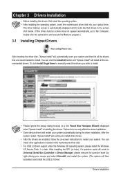
...Drivers Installation • Before installing the drivers, first install the operating system. • After installing the operating system, insert the motherboard driver disk into your mouse and select Uninstall) and restart the system. (The system will continue to install other applications included ... system. Failure to do so may affect the driver installation. • Some device drivers will install all the drivers that shown in the motherboard driver disk. • For USB 2.0 driver support under the Windows XP operating system, please install the Windows XP Service Pack 1 or ...
...Drivers Installation • Before installing the drivers, first install the operating system. • After installing the operating system, insert the motherboard driver disk into your mouse and select Uninstall) and restart the system. (The system will continue to install other applications included ... system. Failure to do so may affect the driver installation. • Some device drivers will install all the drivers that shown in the motherboard driver disk. • For USB 2.0 driver support under the Windows XP operating system, please install the Windows XP Service Pack 1 or ...


