User Manual
Page 2
Motherboard GA-A75M-S2V Jun. 20, 2011 Motherboard GA-A75M-S2V Jun. 20, 2011
Motherboard GA-A75M-S2V Jun. 20, 2011 Motherboard GA-A75M-S2V Jun. 20, 2011
User Manual
Page 3
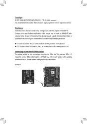
... this product, carefully read the User's Manual. For product-related information, check on our website at: http://www.gigabyte.com Identifying Your Motherboard Revision The revision number on your motherboard revision before updating motherboard BIOS, drivers, or when looking for technical information. No part of this : "REV: X.X." Changes to their respective owners. Example...
... this product, carefully read the User's Manual. For product-related information, check on our website at: http://www.gigabyte.com Identifying Your Motherboard Revision The revision number on your motherboard revision before updating motherboard BIOS, drivers, or when looking for technical information. No part of this : "REV: X.X." Changes to their respective owners. Example...
User Manual
Page 4
Table of Contents GA-A75M-S2V Motherboard Layout 5 GA-A75M-S2V Motherboard Block Diagram 6 Chapter 1 Hardware Installation 7 1-1 Installation Precautions 7 1-2 Product Specifications 8 1-3 Installing the APU 11 1-4 Installing the Memory 12 1-5 Installing an Expansion Card 12 1-6 Setup of the ...
Table of Contents GA-A75M-S2V Motherboard Layout 5 GA-A75M-S2V Motherboard Block Diagram 6 Chapter 1 Hardware Installation 7 1-1 Installation Precautions 7 1-2 Product Specifications 8 1-3 Installing the APU 11 1-4 Installing the Memory 12 1-5 Installing an Expansion Card 12 1-6 Setup of the ...
User Manual
Page 5
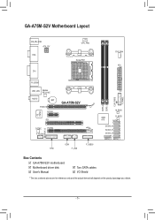
GA-A75M-S2V Motherboard Layout KB_MS_USB ATX_12V VGA DVI CPU_FAN Socket FM1 SYS_FAN ATX DDR3_2 DDR3_1 CLR_CMOS F_PANEL R_USB30 USB_LAN Realtek RTL8111E AUDIO BAT PCIEX16 PCIEX1 iTE IT8720 PCI SPDIF_O CODEC PCIEX4 F_AUDIO GA-A75M-S2V COM F_USB30 TPM F_USB M_BIOS AMD B_BIOS A75 SATA3_5 SATA3_4 SATA3_3 SATA3_2 SATA3_0 SATA3_1 Box Contents GA-A75M-S2V motherboard Motherboard driver disk User's Manual Two SATA cables I/O Shield * The box contents above are for reference only and the actual items shall depend on the product package you obtain. - 5 -
GA-A75M-S2V Motherboard Layout KB_MS_USB ATX_12V VGA DVI CPU_FAN Socket FM1 SYS_FAN ATX DDR3_2 DDR3_1 CLR_CMOS F_PANEL R_USB30 USB_LAN Realtek RTL8111E AUDIO BAT PCIEX16 PCIEX1 iTE IT8720 PCI SPDIF_O CODEC PCIEX4 F_AUDIO GA-A75M-S2V COM F_USB30 TPM F_USB M_BIOS AMD B_BIOS A75 SATA3_5 SATA3_4 SATA3_3 SATA3_2 SATA3_0 SATA3_1 Box Contents GA-A75M-S2V motherboard Motherboard driver disk User's Manual Two SATA cables I/O Shield * The box contents above are for reference only and the actual items shall depend on the product package you obtain. - 5 -
User Manual
Page 6
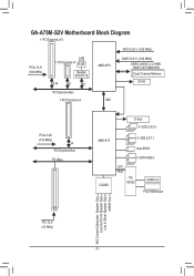
GA-A75M-S2V Motherboard Block Diagram 1 PCI Express x16 PCIe CLK (100 MHz) LAN 1 PCI Express x1 RJ45 Realtek RTL8111E x16 x1 x1 PCI Express Bus 1 PCI Express x4 AMD APU UMI APU CLK+/- (100 MHz) DISP CLK+/- (100 MHz) DDR3 2400(O.C.)/1866/ 1600/1333/1066 MHz Dual Channel Memory DVI-D PCIe CLK (100 MHz) x4 PCI Express Bus PCI Bus D-Sub 4 USB 3.0/2.0 AMD A75 CODEC 6 USB 2.0/1.1 Dual BIOS 6 SATA 6Gb/s LPC Bus iTE IT8720 COM Port PS/2 KB/Mouse 1 PCI PCI CLK (33 MHz) MIC (Center/Subwoofer Speaker Out) Line Out (Front Speaker Out) Line In (Rear Speaker Out) S/PDIF Out - 6 -
GA-A75M-S2V Motherboard Block Diagram 1 PCI Express x16 PCIe CLK (100 MHz) LAN 1 PCI Express x1 RJ45 Realtek RTL8111E x16 x1 x1 PCI Express Bus 1 PCI Express x4 AMD APU UMI APU CLK+/- (100 MHz) DISP CLK+/- (100 MHz) DDR3 2400(O.C.)/1866/ 1600/1333/1066 MHz Dual Channel Memory DVI-D PCIe CLK (100 MHz) x4 PCI Express Bus PCI Bus D-Sub 4 USB 3.0/2.0 AMD A75 CODEC 6 USB 2.0/1.1 Dual BIOS 6 SATA 6Gb/s LPC Bus iTE IT8720 COM Port PS/2 KB/Mouse 1 PCI PCI CLK (33 MHz) MIC (Center/Subwoofer Speaker Out) Line Out (Front Speaker Out) Line In (Rear Speaker Out) S/PDIF Out - 6 -

User Manual
Page 7
... Always remove the AC power by your hands dry and first touch a metal object to eliminate static electricity. • Prior to installing the motherboard, please have a problem related to wear an electrostatic discharge (ESD) wrist strap when handling electronic com- ponents such as physical harm to the... user. • If you are connected tightly and securely. • When handling the motherboard, avoid touching any metal leads or connectors. • It is best to the use of electrostatic discharge (ESD). Prior to installation, ...
... Always remove the AC power by your hands dry and first touch a metal object to eliminate static electricity. • Prior to installing the motherboard, please have a problem related to wear an electrostatic discharge (ESD) wrist strap when handling electronic com- ponents such as physical harm to the... user. • If you are connected tightly and securely. • When handling the motherboard, avoid touching any metal leads or connectors. • It is best to the use of electrostatic discharge (ESD). Prior to installation, ...
User Manual
Page 9
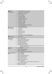
... Center ŠŠ Support for Xpress Install ŠŠ Support for Xpress Recovery2 ŠŠ Support for EasyTune * Available functions in EasyTune may differ by motherboard model. ŠŠ Support for Smart Recovery ŠŠ Support for Auto Green - 9 - Internal Connectors Back Panel Connectors ŠŠ 1 x 24-pin ATX main power...
... Center ŠŠ Support for Xpress Install ŠŠ Support for Xpress Recovery2 ŠŠ Support for EasyTune * Available functions in EasyTune may differ by motherboard model. ŠŠ Support for Smart Recovery ŠŠ Support for Auto Green - 9 - Internal Connectors Back Panel Connectors ŠŠ 1 x 24-pin ATX main power...
User Manual
Page 11
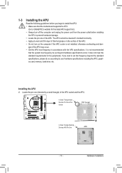
... standard requirements for the latest APU support list.) • Always turn on the computer if the APU cooler is not recommended that the motherboard supports the APU. (Go to GIGABYTE's website for the peripherals. It is not installed, otherwise overheating and dam- 1-3 Installing the APU Read the following guidelines before you wish...
... standard requirements for the latest APU support list.) • Always turn on the computer if the APU cooler is not recommended that the motherboard supports the APU. (Go to GIGABYTE's website for the peripherals. It is not installed, otherwise overheating and dam- 1-3 Installing the APU Read the following guidelines before you wish...
User Manual
Page 12
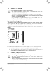
After the memory is recommended that the motherboard supports the memory. Enabling Dual Channel memory mode will automatically detect the specifications and capacity of the same capacity, brand, speed, and chips be used . (Go to GIGABYTE's website for optimum performance. 1-5 Installing an Expansion Card Read the...two memory modules, it is installed, the BIOS will double the original memory bandwidth. Dual Channel Memory Configuration This motherboard provides two DDR3 memory sockets and supports Dual Channel Technology. If you begin to install an expansion card: • Make sure ...
After the memory is recommended that the motherboard supports the memory. Enabling Dual Channel memory mode will automatically detect the specifications and capacity of the same capacity, brand, speed, and chips be used . (Go to GIGABYTE's website for optimum performance. 1-5 Installing an Expansion Card Read the...two memory modules, it is installed, the BIOS will double the original memory bandwidth. Dual Channel Memory Configuration This motherboard provides two DDR3 memory sockets and supports Dual Channel Technology. If you begin to install an expansion card: • Make sure ...
User Manual
Page 13
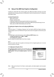
... AMD Dual Graphics technologysupported graphics card on configuring a Dual Graphics system. Browse to the AMD VISION Engine Control Center. C. An AMD Dual Graphics technology-supported motherboard and correct driver - Power off your computer. Installing the Graphics Cards and Configuring BIOS Setup Step 1: Observe the steps in the operating system, go to...
... AMD Dual Graphics technologysupported graphics card on configuring a Dual Graphics system. Browse to the AMD VISION Engine Control Center. C. An AMD Dual Graphics technology-supported motherboard and correct driver - Power off your computer. Installing the Graphics Cards and Configuring BIOS Setup Step 1: Observe the steps in the operating system, go to...
User Manual
Page 14
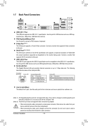
... receiving is occurring Off No data transmission or receiving is compatible to connect a PS/2 mouse or keyboard. Do not rock it straight out from the motherboard. •• When removing the cable, pull it side to side to this audio jack for line in jack. Use this port. Use this port...
... receiving is occurring Off No data transmission or receiving is compatible to connect a PS/2 mouse or keyboard. Do not rock it straight out from the motherboard. •• When removing the cable, pull it side to side to this audio jack for line in jack. Use this port. Use this port...
User Manual
Page 15
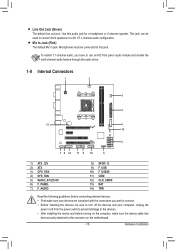
... 3) CPU_FAN 4) SYS_FAN 5) SATA3_0/1/2/3/4/5 6) F_PANEL 7) F_AUDIO 8) SPDIF_O 9) F_USB 10) F_USB30 11) COM 12) CLR_CMOS 13) BAT 14) TPM Read the following guidelines before turning on the motherboard. - 15 - Line Out Jack (Green) The default line out jack.
... 3) CPU_FAN 4) SYS_FAN 5) SATA3_0/1/2/3/4/5 6) F_PANEL 7) F_AUDIO 8) SPDIF_O 9) F_USB 10) F_USB30 11) COM 12) CLR_CMOS 13) BAT 14) TPM Read the following guidelines before turning on the motherboard. - 15 - Line Out Jack (Green) The default line out jack.

User Manual
Page 16
...-pin ATX) GND (Only for 2x12-pin ATX) Hardware Installation - 16 - To meet expansion requirements, it is turned off and all the components on the motherboard. If the 12V power connector is used (400W or greater). Before connecting the power connector, first make sure the power supply is recommended that a power...
...-pin ATX) GND (Only for 2x12-pin ATX) Hardware Installation - 16 - To meet expansion requirements, it is turned off and all the components on the motherboard. If the 12V power connector is used (400W or greater). Before connecting the power connector, first make sure the power supply is recommended that a power...

User Manual
Page 17
3/4) CPU_FAN/SYS_FAN (Fan Headers) The motherboard has a 4-pin APU fan header (CPU_FAN) and a 4-pin system fan header (SYS_FAN). CPU_FAN: Pin No. Do not place a jumper cap oDPnOEtBRhUTeGheaders. 5) SATA3_0/1/2/3/4/5 (SATA 6Gb/s Connectors, ... /Speed Control DEBUG 3 SenPsOeRT 4 Reserve DEBUG •• Be sure to connect fan cables to the fan headers to your APU and system PfrOomRToverheating. The motherboard supports APU fan speed control, which requires the use of hard drives must be used, the SATA cable to prevent your SATA hard the total...
3/4) CPU_FAN/SYS_FAN (Fan Headers) The motherboard has a 4-pin APU fan header (CPU_FAN) and a 4-pin system fan header (SYS_FAN). CPU_FAN: Pin No. Do not place a jumper cap oDPnOEtBRhUTeGheaders. 5) SATA3_0/1/2/3/4/5 (SATA 6Gb/s Connectors, ... /Speed Control DEBUG 3 SenPsOeRT 4 Reserve DEBUG •• Be sure to connect fan cables to the fan headers to your APU and system PfrOomRToverheating. The motherboard supports APU fan speed control, which requires the use of hard drives must be used, the SATA cable to prevent your SATA hard the total...

User Manual
Page 19
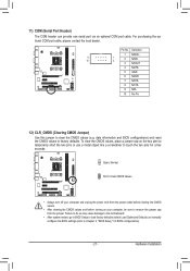
...to certain expansion cards like graphics cards and sound cards. You may require you to use a S/PDIF digital audio cable for your motherboard to this header. For information about connecting the S/PDIF digital audio cable, carefully read the manual for digital audio output from your ...The front panel audio header supports Intel High Definition audio (HD) and AC'97 audio. Incorrect connection between the module connector and the motherboard header will be present on b1oth of the front and back panel audio connections simultaneously. • Some chassis provide a front panel audio ...
...to certain expansion cards like graphics cards and sound cards. You may require you to use a S/PDIF digital audio cable for your motherboard to this header. For information about connecting the S/PDIF digital audio cable, carefully read the manual for digital audio output from your ...The front panel audio header supports Intel High Definition audio (HD) and AC'97 audio. Incorrect connection between the module connector and the motherboard header will be present on b1oth of the front and back panel audio connections simultaneously. • Some chassis provide a front panel audio ...
User Manual
Page 21
... the jumper. Hardware Installation For purchasing the optional COM port cable, please contact the local dealer. Failure to do so may cause damage to the motherboard. •• After system restart, go to BIOS Setup to load factory defaults (select Load Optimized Defaults) or manually configure the BIOS settings (refer to...
... the jumper. Hardware Installation For purchasing the optional COM port cable, please contact the local dealer. Failure to do so may cause damage to the motherboard. •• After system restart, go to BIOS Setup to load factory defaults (select Load Optimized Defaults) or manually configure the BIOS settings (refer to...
User Manual
Page 23
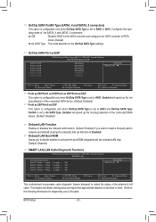
To upgrade the BIOS, use either the GIGABYTE Q-Flash or @BIOS utility. •• Q-Flash allows the... the "Load Optimized Defaults" section in the main menu of the BIOS Setup program. The POST Screen Motherboard Model BIOS Version Award Modular BIOS v6.00PG Copyright (C) 1984-2011, Award Software, Inc. Inadequately altering the... BIOS, do not encounter problems using the current version of the battery/ clearing CMOS jumper in Chapter 1 for how to boot. GA-A75M-S2V F1e . . . . : BIOS Setup : XpressRecovery2 : Boot Menu : Qflash 06/07/2011-Llano-Hudson-7A66HG05C-00 Function Keys...
To upgrade the BIOS, use either the GIGABYTE Q-Flash or @BIOS utility. •• Q-Flash allows the... the "Load Optimized Defaults" section in the main menu of the BIOS Setup program. The POST Screen Motherboard Model BIOS Version Award Modular BIOS v6.00PG Copyright (C) 1984-2011, Award Software, Inc. Inadequately altering the... BIOS, do not encounter problems using the current version of the battery/ clearing CMOS jumper in Chapter 1 for how to boot. GA-A75M-S2V F1e . . . . : BIOS Setup : XpressRecovery2 : Boot Menu : Qflash 06/07/2011-Llano-Hudson-7A66HG05C-00 Function Keys...
User Manual
Page 32
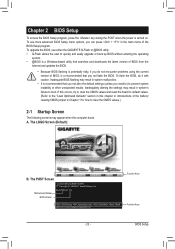
...; Move Enter: Select F5: Previous Values +/-/PU/PD: Value F10: Save F6: Fail-Safe Defaults ESC: Exit F1: General Help F7: Optimized Defaults This motherboard incorporates cable diagnostic feature designed to PATA mode. (Default) As SATA Type The mode depends on the OnChip SATA Type settings. OnChip SATA Port4/5 Type...
...; Move Enter: Select F5: Previous Values +/-/PU/PD: Value F10: Save F6: Fail-Safe Defaults ESC: Exit F1: General Help F7: Optimized Defaults This motherboard incorporates cable diagnostic feature designed to PATA mode. (Default) As SATA Type The mode depends on the OnChip SATA Type settings. OnChip SATA Port4/5 Type...
User Manual
Page 35
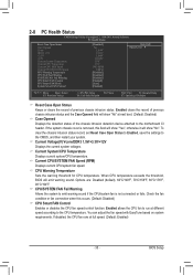
...: Exit F1: General Help F7: Optimized Defaults Reset Case Open Status Keeps or clears the record of the chassis intrusion detection device attached to the motherboard CI header. CPU Warning Temperature Sets the warning threshold for CPU temperature. Check the fan condition or fan connection when this field will show "Yes...
...: Exit F1: General Help F7: Optimized Defaults Reset Case Open Status Keeps or clears the record of the chassis intrusion detection device attached to the motherboard CI header. CPU Warning Temperature Sets the warning threshold for CPU temperature. Check the fan condition or fan connection when this field will show "Yes...
User Manual
Page 36
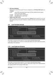
... Press on this item and then press the key to load Fail-Safe defaults, which are the safest and most stable BIOS settings for the motherboard. 2-10 Load Optimized Defaults CMOS Setup Utility-Copyright (C) 1984-2011 Award Software MB Intelligent Tweaker(M.I .T.) Load Fail-Safe Defaults Standard CMOS Features Load...
... Press on this item and then press the key to load Fail-Safe defaults, which are the safest and most stable BIOS settings for the motherboard. 2-10 Load Optimized Defaults CMOS Setup Utility-Copyright (C) 1984-2011 Award Software MB Intelligent Tweaker(M.I .T.) Load Fail-Safe Defaults Standard CMOS Features Load...


