User Manual
Page 1
GA-A75-UD4H User's Manual Rev. 1002 12ME-A75UD4H-1002R
GA-A75-UD4H User's Manual Rev. 1002 12ME-A75UD4H-1002R

User Manual
Page 3
... 1.0" means the revision of the motherboard is the property of GIGABYTE. Changes to the specifications and features in this manual may be reproduced, copied, translated, transmitted, or published in this manual is protected by copyright laws and is 1.0. Documentation Classifications In order... with the product. For detailed product information, carefully read the User's Manual. For product-related information, check on our website at: http://www.gigabyte.com Identifying Your Motherboard Revision The revision number on your motherboard revision before updating motherboard...
... 1.0" means the revision of the motherboard is the property of GIGABYTE. Changes to the specifications and features in this manual may be reproduced, copied, translated, transmitted, or published in this manual is protected by copyright laws and is 1.0. Documentation Classifications In order... with the product. For detailed product information, carefully read the User's Manual. For product-related information, check on our website at: http://www.gigabyte.com Identifying Your Motherboard Revision The revision number on your motherboard revision before updating motherboard...

User Manual
Page 5
Chapter 3 Drivers Installation 57 3-1 Installing Chipset Drivers 57 3-2 Application Software 58 3-3 Technical Manuals 58 3-4 Contact...59 3-5 System...59 3-6 Download Center 60 3-7 New Utilities...60 Chapter 4 Unique Features 61 4-1 Xpress Recovery2 61 4-2 BIOS Update Utilities 64 4-2-1 Updating the BIOS ...
Chapter 3 Drivers Installation 57 3-1 Installing Chipset Drivers 57 3-2 Application Software 58 3-3 Technical Manuals 58 3-4 Contact...59 3-5 System...59 3-6 Download Center 60 3-7 New Utilities...60 Chapter 4 Unique Features 61 4-1 Xpress Recovery2 61 4-2 BIOS Update Utilities 64 4-2-1 Updating the BIOS ...

User Manual
Page 6
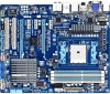
The box contents are for reference only and the actual items shall depend on the product package you obtain. Optional Items 2-port USB 2.0 bracket (Part No. 12CR1-1UB030-5*R) 2-port SATA power cable (Part No. 12CF1-2SERPW-0*R) 2-port IEEE 1394a bracket (Part No. 12CF1-1IE008-0*R) COM port cable (Part No. 12CF1-1CM001-3*R) 3.5" Front Panel with 2 USB 3.0/2.0 ports (Part No. 12CR1-FPX582-0*R) - 6 - Box Contents GA-A75-UD4H motherboard Motherboard driver disk User's Manual Quick Installation Guide Four SATA cables I/O Shield The box contents above are subject to change without notice.
The box contents are for reference only and the actual items shall depend on the product package you obtain. Optional Items 2-port USB 2.0 bracket (Part No. 12CR1-1UB030-5*R) 2-port SATA power cable (Part No. 12CF1-2SERPW-0*R) 2-port IEEE 1394a bracket (Part No. 12CF1-1IE008-0*R) COM port cable (Part No. 12CF1-1CM001-3*R) 3.5" Front Panel with 2 USB 3.0/2.0 ports (Part No. 12CR1-FPX582-0*R) - 6 - Box Contents GA-A75-UD4H motherboard Motherboard driver disk User's Manual Quick Installation Guide Four SATA cables I/O Shield The box contents above are subject to change without notice.

User Manual
Page 9
... motherboard, please have a problem related to the use of the product, please consult a certified computer technician. - 9 - Hardware Installation Prior to installation, carefully read the user's manual and follow these procedures: • Prior to installation, do not remove or break motherboard S/N (Serial Number) sticker or warranty sticker provided by unplugging the power...
... motherboard, please have a problem related to the use of the product, please consult a certified computer technician. - 9 - Hardware Installation Prior to installation, carefully read the user's manual and follow these procedures: • Prior to installation, do not remove or break motherboard S/N (Serial Number) sticker or warranty sticker provided by unplugging the power...

User Manual
Page 15
... the steps below to correctly install the APU cooler on the APU. (The following procedure uses the GIGABYTE cooler as the picture above shows) to lock into place. (Refer to your APU cooler installation manual for instructions on installing the cooler.) Step 5: Finally, attach the power connector of the APU cooler to...
... the steps below to correctly install the APU cooler on the APU. (The following procedure uses the GIGABYTE cooler as the picture above shows) to lock into place. (Refer to your APU cooler installation manual for instructions on installing the cooler.) Step 5: Finally, attach the power connector of the APU cooler to...

User Manual
Page 18
...(s). 6. Install the driver provided with your computer. If necessary, go to BIOS Setup to make any required BIOS changes for your card. Carefully read the manual that supports your expansion card(s). 7. Hardware Installation - 18 - • Removing the Card from the power outlet before you begin to install an expansion card: •...
...(s). 6. Install the driver provided with your computer. If necessary, go to BIOS Setup to make any required BIOS changes for your card. Carefully read the manual that supports your expansion card(s). 7. Hardware Installation - 18 - • Removing the Card from the power outlet before you begin to install an expansion card: •...

User Manual
Page 28
... that has separated connectors on both of the motherboard header. If your expan- For information about connecting the S/PDIF digital audio cable, carefully read the manual for digital audio output from your motherboard to your motherboard to certain expansion cards like graphics cards and sound cards. 9) F_AUDIO (Front Panel Audio Header...
... that has separated connectors on both of the motherboard header. If your expan- For information about connecting the S/PDIF digital audio cable, carefully read the manual for digital audio output from your motherboard to your motherboard to certain expansion cards like graphics cards and sound cards. 9) F_AUDIO (Front Panel Audio Header...

User Manual
Page 31
...) You may cause damage to the motherboard. •• After system restart, go to BIOS Setup to load factory defaults (select Load Optimized Defaults) or manually configure the BIOS settings (refer to factory defaults. DIP 1 23 PCIe power connector (SATA)(X58A-OC) 20 19 2 1 Pin No. 1 2 3 4 5 6 7 8 9 10 Definition LCLK GND LFRAME...
...) You may cause damage to the motherboard. •• After system restart, go to BIOS Setup to load factory defaults (select Load Optimized Defaults) or manually configure the BIOS settings (refer to factory defaults. DIP 1 23 PCIe power connector (SATA)(X58A-OC) 20 19 2 1 Pin No. 1 2 3 4 5 6 7 8 9 10 Definition LCLK GND LFRAME...
User Manual
Page 38
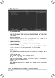
... mode is enabled. (Default: Disabled) VGA Core Clock control Allows you to determine whether to manually set the VGA Core clock. (Default: Auto) VGA Core Clock(MHz) Allows you to manually set to alter the frequency of system memory allocated solely for the installed CPU. Options are: ...CPU NorthBridge Freq. The adjustable range is dependent on the CPU being installed. (Default: Auto) (Note) This item is present only when you to Manual. The adjustable range is dependent on the CPU being installed. Allows you install a CPU that the DisplayPort, D-Sub, and HDMI ports will use only...
... mode is enabled. (Default: Disabled) VGA Core Clock control Allows you to determine whether to manually set the VGA Core clock. (Default: Auto) VGA Core Clock(MHz) Allows you to manually set to alter the frequency of system memory allocated solely for the installed CPU. Options are: ...CPU NorthBridge Freq. The adjustable range is dependent on the CPU being installed. (Default: Auto) (Note) This item is present only when you to Manual. The adjustable range is dependent on the CPU being installed. Allows you install a CPU that the DisplayPort, D-Sub, and HDMI ports will use only...
User Manual
Page 39
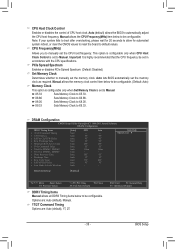
... DIMM2, DIMM4 x Trfc1 for automated system reboot, or clear the CMOS values to reset the board to Manual. CPU Host Clock Control Enables or disables the control of CPU host clock. X6.66 Sets Memory Clock ...to X9.33. Auto -9T 9T 9T 24T 5T 110ns -6T 4T 20T 4T -- Manual allows the CPU Frequency(MHz) item below to be set to default values. ESC: Exit F1: General Help...Auto SPD -9T 9T 9T 24T 5T 110ns -10T 5T 33T 4T -- Options are: Auto (default), Manual. 1T/2T Command Timing Options are: Auto (default), 1T, 2T. BIOS Setup This option is configurable ...
... DIMM2, DIMM4 x Trfc1 for automated system reboot, or clear the CMOS values to reset the board to Manual. CPU Host Clock Control Enables or disables the control of CPU host clock. X6.66 Sets Memory Clock ...to X9.33. Auto -9T 9T 9T 24T 5T 110ns -6T 4T 20T 4T -- Manual allows the CPU Frequency(MHz) item below to be set to default values. ESC: Exit F1: General Help...Auto SPD -9T 9T 9T 24T 5T 110ns -10T 5T 33T 4T -- Options are: Auto (default), Manual. 1T/2T Command Timing Options are: Auto (default), 1T, 2T. BIOS Setup This option is configurable ...

User Manual
Page 40
... Auto (default), 4T~8T. TwTr Command Delay Options are : Auto (default), 15T~36T. Note: Increasing CPU voltage may result in damage to manually set the system voltages as required. Precharge Time Options are : Auto (default), 16T~40T. Four Bank Activate Window Options are : Auto (default), 4T...~8T. Manual allows all voltage control items below to be configurable. (Default: Auto) CPU PLL Voltage Control Allows you to 2.900V. Normal Supplies the CPU...
... Auto (default), 4T~8T. TwTr Command Delay Options are : Auto (default), 15T~36T. Note: Increasing CPU voltage may result in damage to manually set the system voltages as required. Precharge Time Options are : Auto (default), 16T~40T. Four Bank Activate Window Options are : Auto (default), 4T...~8T. Manual allows all voltage control items below to be configurable. (Default: Auto) CPU PLL Voltage Control Allows you to 2.900V. Normal Supplies the CPU...

User Manual
Page 57
... the Install All button and "Xpress Install" will install all of the drivers, a dialog box will appear asking whether to install new GIGABYTE utilities. Click Yes to install. Or click No if you wish to My Computer, double-click the optical drive and execute the Run...in Device Manager, please remove the question mark (by right-clicking your optical drive. Or click Install Single Items to manually select the drivers you want to manually select the utilities to install other drivers. • After "Xpress Install" installs all the recommended drivers. Drivers Installation ...
... the Install All button and "Xpress Install" will install all of the drivers, a dialog box will appear asking whether to install new GIGABYTE utilities. Click Yes to install. Or click No if you wish to My Computer, double-click the optical drive and execute the Run...in Device Manager, please remove the question mark (by right-clicking your optical drive. Or click Install Single Items to manually select the drivers you want to manually select the utilities to install other drivers. • After "Xpress Install" installs all the recommended drivers. Drivers Installation ...

User Manual
Page 58
3-2 Application Software This page displays all the utilities and applications that GIGABYTE develops and some free software. Drivers Installation - 58 - You can click the Install button on the right of an item to install it. 3-3 Technical Manuals This page provides GIGABYTE's application guides, content descriptions for this driver disk, and the motherboard manuals.
3-2 Application Software This page displays all the utilities and applications that GIGABYTE develops and some free software. Drivers Installation - 58 - You can click the Install button on the right of an item to install it. 3-3 Technical Manuals This page provides GIGABYTE's application guides, content descriptions for this driver disk, and the motherboard manuals.

User Manual
Page 64
... without the need to update the system BIOS while in the BIOS, the Q-Flash tool frees you to enter MS-DOS mode. Unique Features - 64 - GA-A75-UD4H F1b . . . . : BIOS Setup : XpressRecovery2 : Boot Menu : Qflash 05/25/2011-Llano-Hudson-7A66HG01C-00 Because BIOS flashing is @BIOS™? @...corrupted or damaged, the backup BIOS will download the latest BIOS file from the hassles of system safety, users cannot update the backup BIOS manually. GIGABYTE Q-Flash and @BIOS are easy-to ensure normal system operation. However, if the main BIOS is Q-Flash™? For the sake of...
... without the need to update the system BIOS while in the BIOS, the Q-Flash tool frees you to enter MS-DOS mode. Unique Features - 64 - GA-A75-UD4H F1b . . . . : BIOS Setup : XpressRecovery2 : Boot Menu : Qflash 05/25/2011-Llano-Hudson-7A66HG01C-00 Because BIOS flashing is @BIOS™? @...corrupted or damaged, the backup BIOS will download the latest BIOS file from the hassles of system safety, users cannot update the backup BIOS manually. GIGABYTE Q-Flash and @BIOS are easy-to ensure normal system operation. However, if the main BIOS is Q-Flash™? For the sake of...

User Manual
Page 67
...your location and then download the BIOS file that matches your motherboard is not present on the @BIOS server site, please manually download the BIOS update file from GIGABYTE's website and follow the instructions in a corrupted BIOS or a system that the BIOS file to be flashed matches your... boot. - 67 - Make sure that is stable and do NOT interrupt the Internet connection (for your motherboard model. Do not use the G.O.M. (GIGABYTE Online Management) function when using @BIOS. 4. If the BIOS update file for example, avoid a power loss or switching off the Internet). Load BIOS...
...your location and then download the BIOS file that matches your motherboard is not present on the @BIOS server site, please manually download the BIOS update file from GIGABYTE's website and follow the instructions in a corrupted BIOS or a system that the BIOS file to be flashed matches your... boot. - 67 - Make sure that is stable and do NOT interrupt the Internet connection (for your motherboard model. Do not use the G.O.M. (GIGABYTE Online Management) function when using @BIOS. 4. If the BIOS update file for example, avoid a power loss or switching off the Internet). Load BIOS...

User Manual
Page 76
... down arrow key to move to enter the LD View Menu window (Figure 4). Option ROM Utility (c) 2011 Advanced Micro Devices, Inc. Create Arrays Manually To create a new array, press to an item for further configuration (Figure 5). To create an array, press to access the LD Define Menu.... LD No LD Name LD 1 Logical Drive 1 [ LD Define Menu ] RAID Mode Drv RAID 0 0 Stripe Block Gigabyte Boundary Read Policy 64 KB ON Read Ahead Initialization Fast Write Policy WriteBack [ Drives Assignments ] Port:ID 01:00 02:00 Drive Model WDC WD800JD...
... down arrow key to move to enter the LD View Menu window (Figure 4). Option ROM Utility (c) 2011 Advanced Micro Devices, Inc. Create Arrays Manually To create a new array, press to an item for further configuration (Figure 5). To create an array, press to access the LD Define Menu.... LD No LD Name LD 1 Logical Drive 1 [ LD Define Menu ] RAID Mode Drv RAID 0 0 Stripe Block Gigabyte Boundary Read Policy 64 KB ON Read Ahead Initialization Fast Write Policy WriteBack [ Drives Assignments ] Port:ID 01:00 02:00 Drive Model WDC WD800JD...

User Manual
Page 83
For example, in jack and manually configure the jack for multi-channel speaker configurations. • 2-channel audio: Headphone or Line out. • 4-channel audio: Front speaker out and Side speaker out. &#...
For example, in jack and manually configure the jack for multi-channel speaker configurations. • 2-channel audio: Headphone or Line out. • 4-channel audio: Front speaker out and Side speaker out. &#...


