User Manual
Page 2
Motherboard GA-A55M-DS2 Aug. 26, 2011 Motherboard GA-A55M-DS2 Aug. 26, 2011
Motherboard GA-A55M-DS2 Aug. 26, 2011 Motherboard GA-A55M-DS2 Aug. 26, 2011
User Manual
Page 3
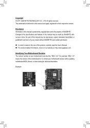
... Manual. For product-related information, check on our website at: http://www.gigabyte.com Identifying Your Motherboard Revision The revision number on your motherboard revision before updating motherboard BIOS, drivers, or when looking for technical information. Example: No part of this manual...legally registered to assist in this manual may be made by copyright laws and is the property of the motherboard is protected by GIGABYTE without GIGABYTE's prior written permission. In order to their respective owners. Disclaimer Information in this manual is 1.0....
... Manual. For product-related information, check on our website at: http://www.gigabyte.com Identifying Your Motherboard Revision The revision number on your motherboard revision before updating motherboard BIOS, drivers, or when looking for technical information. Example: No part of this manual...legally registered to assist in this manual may be made by copyright laws and is the property of the motherboard is protected by GIGABYTE without GIGABYTE's prior written permission. In order to their respective owners. Disclaimer Information in this manual is 1.0....
User Manual
Page 4
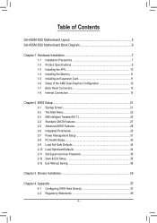
Table of Contents GA-A55M-DS2 Motherboard Layout 5 GA-A55M-DS2 Motherboard Block Diagram 6 Chapter 1 Hardware Installation 7 1-1 Installation Precautions 7 1-2 Product Specifications 8 1-3 Installing the APU 10 1-4 Installing the Memory 11 1-5 Installing an Expansion Card 11 1-6 Setup of the ...
Table of Contents GA-A55M-DS2 Motherboard Layout 5 GA-A55M-DS2 Motherboard Block Diagram 6 Chapter 1 Hardware Installation 7 1-1 Installation Precautions 7 1-2 Product Specifications 8 1-3 Installing the APU 10 1-4 Installing the Memory 11 1-5 Installing an Expansion Card 11 1-6 Setup of the ...
User Manual
Page 5
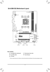
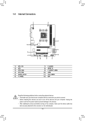
GA-A55M-DS2 Motherboard Layout KB_MS ATX_12V VGA CPU_FAN Socket FM1 DVI ATX R_USB USB_LAN DDR3_2 DDR3_1 AUDIO Realtek/Atheros GbE LAN PCIEX16 BAT GA-A55M-DS2 iTE IT8728 PCIEX1 SATA2_3 AMD A55 SATA2_2 PCI CODEC COM F_AUDIO F_USB1 SATA2_1 SATA2_0 CLR_CMOS SYS_FAN SPDIF_O M_BIOS B_BIOS F_USB2 F_PANEL Box Contents GA-A55M-DS2 motherboard Two SATA cables I/O Shield Motherboard driver disk User's Manual * The box contents above are for reference only and the actual items shall depend on the product package you obtain. - 5 -
GA-A55M-DS2 Motherboard Layout KB_MS ATX_12V VGA CPU_FAN Socket FM1 DVI ATX R_USB USB_LAN DDR3_2 DDR3_1 AUDIO Realtek/Atheros GbE LAN PCIEX16 BAT GA-A55M-DS2 iTE IT8728 PCIEX1 SATA2_3 AMD A55 SATA2_2 PCI CODEC COM F_AUDIO F_USB1 SATA2_1 SATA2_0 CLR_CMOS SYS_FAN SPDIF_O M_BIOS B_BIOS F_USB2 F_PANEL Box Contents GA-A55M-DS2 motherboard Two SATA cables I/O Shield Motherboard driver disk User's Manual * The box contents above are for reference only and the actual items shall depend on the product package you obtain. - 5 -
User Manual
Page 6
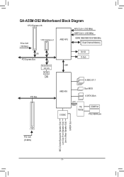
GA-A55M-DS2 Motherboard Block Diagram 1 PCI Express x16 APU CLK+/- (100 MHz) DISP CLK+/- (100 MHz) PCIe CLK (100 MHz) 1 PCI Express x1 AMD APU DDR3 1866/1600/1333/1066 MHz Dual Channel Memory x16 x1 PCI Express Bus x1 DVI-D D-Sub Realtek/Atheros UMI GbE LAN RJ45 LAN 8 USB 2.0/1.1 PCI Bus AMD A55 CODEC Dual BIOS 4 SATA 3Gb/s LPC Bus iTE IT8728 COM Port PS/2 KB/Mouse 1 PCI PCI CLK (33 MHz) MIC (Center/Subwoofer Speaker Out) Line Out (Front Speaker Out) Line In (Rear Speaker Out) S/PDIF Out - 6 -
GA-A55M-DS2 Motherboard Block Diagram 1 PCI Express x16 APU CLK+/- (100 MHz) DISP CLK+/- (100 MHz) PCIe CLK (100 MHz) 1 PCI Express x1 AMD APU DDR3 1866/1600/1333/1066 MHz Dual Channel Memory x16 x1 PCI Express Bus x1 DVI-D D-Sub Realtek/Atheros UMI GbE LAN RJ45 LAN 8 USB 2.0/1.1 PCI Bus AMD A55 CODEC Dual BIOS 4 SATA 3Gb/s LPC Bus iTE IT8728 COM Port PS/2 KB/Mouse 1 PCI PCI CLK (33 MHz) MIC (Center/Subwoofer Speaker Out) Line Out (Front Speaker Out) Line In (Rear Speaker Out) S/PDIF Out - 6 -
User Manual
Page 7
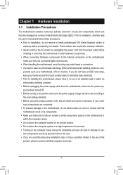
... •• Always remove the AC power by your hardware components are connected. •• To prevent damage to the motherboard, do not remove or break motherboard S/N (Serial Number) sticker or warranty sticker provided by unplugging the power cord from the power outlet before installing or removing the... ESD wrist strap, keep your hands dry and first touch a metal object to eliminate static electricity. •• Prior to installing the motherboard, please have it on top of an antistatic pad or within the computer casing. •• Do not place the computer system on ...
... •• Always remove the AC power by your hardware components are connected. •• To prevent damage to the motherboard, do not remove or break motherboard S/N (Serial Number) sticker or warranty sticker provided by unplugging the power cord from the power outlet before installing or removing the... ESD wrist strap, keep your hands dry and first touch a metal object to eliminate static electricity. •• Prior to installing the motherboard, please have it on top of an antistatic pad or within the computer casing. •• Do not place the computer system on ...
User Manual
Page 9
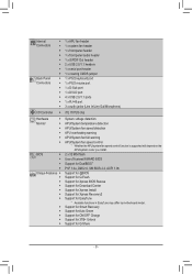
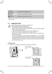
... Center ŠŠ Support for Xpress Install ŠŠ Support for Xpress Recovery2 ŠŠ Support for EasyTune * Available functions in EasyTune may differ by motherboard model. ŠŠ Support for Smart Recovery ŠŠ Support for Auto Green ŠŠ Support for ON/OFF Charge ŠŠ Support for 3TB...
... Center ŠŠ Support for Xpress Install ŠŠ Support for Xpress Recovery2 ŠŠ Support for EasyTune * Available functions in EasyTune may differ by motherboard model. ŠŠ Support for Smart Recovery ŠŠ Support for Auto Green ŠŠ Support for ON/OFF Charge ŠŠ Support for 3TB...
User Manual
Page 10
It is not recommended that the motherboard supports the APU. (Go to GIGABYTE's website for the latest APU support list.) • Always turn on the computer if the APU cooler is not installed, otherwise overheating and dam- If ...
It is not recommended that the motherboard supports the APU. (Go to GIGABYTE's website for the latest APU support list.) • Always turn on the computer if the APU cooler is not installed, otherwise overheating and dam- If ...
User Manual
Page 11
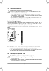
... the memory: •• Make sure that memory of the same capacity, brand, speed, and chips be used . (Go to GIGABYTE's website for optimum performance. 1-5 Installing an Expansion Card Read the following guidelines before installing the memory in only one DDR3 memory module is... the manual that came with two memory modules, it is recommended that memory of the memory. After the memory is recommended that the motherboard supports the memory. Carefully read the following guidelines before installing an expansion card to prevent hardware damage. - 11 - It is installed...
... the memory: •• Make sure that memory of the same capacity, brand, speed, and chips be used . (Go to GIGABYTE's website for optimum performance. 1-5 Installing an Expansion Card Read the following guidelines before installing the memory in only one DDR3 memory module is... the manual that came with two memory modules, it is recommended that memory of the memory. After the memory is recommended that the motherboard supports the memory. Carefully read the following guidelines before installing an expansion card to prevent hardware damage. - 11 - It is installed...
User Manual
Page 12
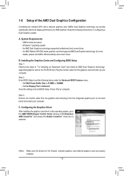
...™ and ensure the Enable CrossFire™ check box is selected. (Note) Make sure the drivers for AMD platform. An AMD Dual Graphics technology-supported motherboard and correct driver - Set Init Display First to 512MB or 1024MB. - A. Installing the Graphics Cards and Configuring BIOS Setup Step 1: Observe the steps in the...
...™ and ensure the Enable CrossFire™ check box is selected. (Note) Make sure the drivers for AMD platform. An AMD Dual Graphics technology-supported motherboard and correct driver - Set Init Display First to 512MB or 1024MB. - A. Installing the Graphics Cards and Configuring BIOS Setup Step 1: Observe the steps in the...
User Manual
Page 13
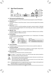
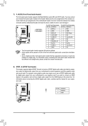
... for line in jack. Use this port for USB devices such as an optical drive, walkman, etc. Do not rock it straight out from the motherboard. •• When removing the cable, pull it side to side to connect front speakers in jack. DVI-D Port (Note 1)(Note 2) The DVI-D port conforms...
... for line in jack. Use this port for USB devices such as an optical drive, walkman, etc. Do not rock it straight out from the motherboard. •• When removing the cable, pull it side to side to connect front speakers in jack. DVI-D Port (Note 1)(Note 2) The DVI-D port conforms...
User Manual
Page 14
... sure your devices are compliant with the connectors you wish to connect. •• Before installing the devices, be sure to the connector on the motherboard. - 14 - Unplug the power cord from the power outlet to prevent damage to the devices. •• After installing the device and before connecting external...
... sure your devices are compliant with the connectors you wish to connect. •• Before installing the devices, be sure to the connector on the motherboard. - 14 - Unplug the power cord from the power outlet to prevent damage to the devices. •• After installing the device and before connecting external...
User Manual
Page 15
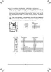
... can lead to the APU. The power connector possesses a foolproof design. To meet expansion requirements, it is turned off and all the components on the motherboard. Connect the power supply cable to all devices are properly installed. If the 12V power connector is used (500W or greater). 1/2) ATX_12V/ATX (2x2 12V...
... can lead to the APU. The power connector possesses a foolproof design. To meet expansion requirements, it is turned off and all the components on the motherboard. Connect the power supply cable to all devices are properly installed. If the 12V power connector is used (500W or greater). 1/2) ATX_12V/ATX (2x2 12V...
User Manual
Page 16
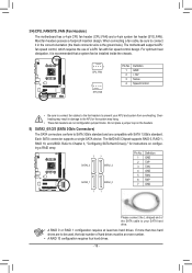
... jumper blocks. The AMD A55 Chipset supports RAID 0, RAID 1, RAID 10, and JBOD. 3/4) CPU_FAN/SYS_FAN (Fan Headers) The motherboard has a 4-pin CPU fan header (CPU_FAN) and a 4-pin system fan header (SYS_FAN). The motherboard supports APU fan speed control, which requires the use of hard drives must be an even number. • A RAID...
... jumper blocks. The AMD A55 Chipset supports RAID 0, RAID 1, RAID 10, and JBOD. 3/4) CPU_FAN/SYS_FAN (Fan Headers) The motherboard has a 4-pin CPU fan header (CPU_FAN) and a 4-pin system fan header (SYS_FAN). The motherboard supports APU fan speed control, which requires the use of hard drives must be an even number. • A RAID...
User Manual
Page 18
...graphics cards and sound cards. Definition Pin No. Definition 1 SPDIFO 1 2 GND - 18 - Incorrect connection between the module connector and the motherboard header will be present on each wire instead of the front and back panel audio connections simultane- ously. •• Some chassis provide a... the module connector match the pin assignments of the motherboard header. You may require you to use a S/PDIF digital audio cable for your motherboard to the graphics card and have digital audio output from your motherboard to your chassis front panel audio module to work...
...graphics cards and sound cards. Definition Pin No. Definition 1 SPDIFO 1 2 GND - 18 - Incorrect connection between the module connector and the motherboard header will be present on each wire instead of the front and back panel audio connections simultane- ously. •• Some chassis provide a... the module connector match the pin assignments of the motherboard header. You may require you to use a S/PDIF digital audio cable for your motherboard to the graphics card and have digital audio output from your motherboard to your chassis front panel audio module to work...
User Manual
Page 20
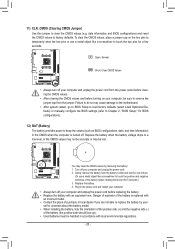
..., place a jumper cap on your computer and unplug the power cord. 222 Gently remove the battery from the jumper. You may cause damage to the motherboard. •• After system restart, go to BIOS Setup to load factory defaults (select Load Optimized Defaults) or manually configure the BIOS settings (refer to...
..., place a jumper cap on your computer and unplug the power cord. 222 Gently remove the battery from the jumper. You may cause damage to the motherboard. •• After system restart, go to BIOS Setup to load factory defaults (select Load Optimized Defaults) or manually configure the BIOS settings (refer to...
User Manual
Page 21
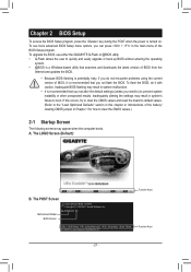
...unexpected results. If this chapter or introductions of BIOS, it with caution. A. GA-A55M-DS2 E9 . . . . : BIOS Setup : XpressRecovery2 : Boot Menu : Qflash 07/19/2011-Llano-Hudson-7A66HG0DC-00 Function Keys Function Keys - 21 - To upgrade the BIOS, use either the GIGABYTE Q-Flash or @BIOS utility. •• Q-Flash allows the user to... the POST when the power is recommended that you not alter the default settings (unless you need to) to boot. The POST Screen Motherboard Model BIOS Version Award Modular BIOS v6.00PG Copyright (C) 1984-2011, Award Software, Inc.
...unexpected results. If this chapter or introductions of BIOS, it with caution. A. GA-A55M-DS2 E9 . . . . : BIOS Setup : XpressRecovery2 : Boot Menu : Qflash 07/19/2011-Llano-Hudson-7A66HG0DC-00 Function Keys Function Keys - 21 - To upgrade the BIOS, use either the GIGABYTE Q-Flash or @BIOS utility. •• Q-Flash allows the user to... the POST when the power is recommended that you not alter the default settings (unless you need to) to boot. The POST Screen Motherboard Model BIOS Version Award Modular BIOS v6.00PG Copyright (C) 1984-2011, Award Software, Inc.
User Manual
Page 30
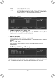
...; Move Enter: Select F5: Previous Values +/-/PU/PD: Value F10: Save F6: Fail-Safe Defaults ESC: Exit F1: General Help F7: Optimized Defaults This motherboard incorporates cable diagnostic feature designed to enable advanced Serial ATA features such as ESP This option is configurable only when OnChip SATA Type is an...
...; Move Enter: Select F5: Previous Values +/-/PU/PD: Value F10: Save F6: Fail-Safe Defaults ESC: Exit F1: General Help F7: Optimized Defaults This motherboard incorporates cable diagnostic feature designed to enable advanced Serial ATA features such as ESP This option is configurable only when OnChip SATA Type is an...
User Manual
Page 33
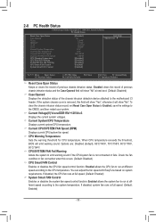
...: Exit F1: General Help F7: Optimized Defaults Reset Case Open Status Keeps or clears the record of the chassis intrusion detection device attached to the motherboard CI header. Enabled clears the record of previous chassis intrusion status and the Case Opened field will emit warning sound.
...: Exit F1: General Help F7: Optimized Defaults Reset Case Open Status Keeps or clears the record of the chassis intrusion detection device attached to the motherboard CI header. Enabled clears the record of previous chassis intrusion status and the Case Opened field will emit warning sound.
User Manual
Page 34
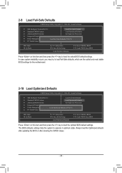
... settings. In case system instability occurs, you may try to load Fail-Safe defaults, which are the safest and most stable BIOS settings for the motherboard. 2-10 Load Optimized Defaults CMOS Setup Utility-Copyright (C) 1984-2011 Award Software MB Intelligent Tweaker(M.I .T.) Load Fail-Safe Defaults Standard CMOS Features Load...
... settings. In case system instability occurs, you may try to load Fail-Safe defaults, which are the safest and most stable BIOS settings for the motherboard. 2-10 Load Optimized Defaults CMOS Setup Utility-Copyright (C) 1984-2011 Award Software MB Intelligent Tweaker(M.I .T.) Load Fail-Safe Defaults Standard CMOS Features Load...


