
Manual
Page 3
... part of the motherboard is protected by GIGABYTE without GIGABYTE's prior written permission. For product-related information, check on our website at: http://www.gigabyte.com Identifying Your Motherboard Revision The revision number on your motherboard revision before updating motherboard BIOS, drivers, ...published in the use of this : "REV: X.X." Check your motherboard looks like this product, GIGABYTE provides the following types of documentations: For quick set-up of GIGABYTE. Example: Documentation Classifications In order to their respective owners. The ...
... part of the motherboard is protected by GIGABYTE without GIGABYTE's prior written permission. For product-related information, check on our website at: http://www.gigabyte.com Identifying Your Motherboard Revision The revision number on your motherboard revision before updating motherboard BIOS, drivers, ...published in the use of this : "REV: X.X." Check your motherboard looks like this product, GIGABYTE provides the following types of documentations: For quick set-up of GIGABYTE. Example: Documentation Classifications In order to their respective owners. The ...

Manual
Page 4
Table of Contents Box Contents...6 Optional Items...6 GA-990FXA-UD7 Motherboard Layout 7 GA-990FXA-UD7 Motherboard Block Diagram 8 Chapter 1 Hardware Installation 9 1-1 Installation Precautions 9 1-2 Product Specifications 10 1-3 Installing the CPU and CPU Cooler 13 1-3-1 Installing the CPU 13 1-3-2 Installing the CPU Cooler ...
Table of Contents Box Contents...6 Optional Items...6 GA-990FXA-UD7 Motherboard Layout 7 GA-990FXA-UD7 Motherboard Block Diagram 8 Chapter 1 Hardware Installation 9 1-1 Installation Precautions 9 1-2 Product Specifications 10 1-3 Installing the CPU and CPU Cooler 13 1-3-1 Installing the CPU 13 1-3-2 Installing the CPU Cooler ...
Manual
Page 6
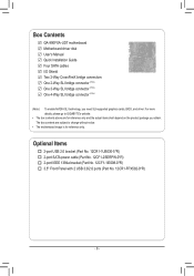
... more details, please go to GIGABYTE's website. • The box contents above are subject to change without notice. • The motherboard image is for reference only and the actual items shall depend on the product package you need SLI-supported graphics cards, BIOS, and driver. Box Contents GA-990FXA-UD7 motherboard Motherboard driver disk User's Manual Quick...
... more details, please go to GIGABYTE's website. • The box contents above are subject to change without notice. • The motherboard image is for reference only and the actual items shall depend on the product package you need SLI-supported graphics cards, BIOS, and driver. Box Contents GA-990FXA-UD7 motherboard Motherboard driver disk User's Manual Quick...

Manual
Page 7
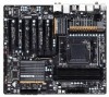
GA-990FXA-UD7 Motherboard Layout KB_MS_USB ATX_12V R_SPDIF USB_1394_ESATA Marvell 88SE9172 USB_ESATA CPU_FAN Socket AM3+ PWR_FAN DDR3_4 DDR3_2 DDR3_3 DDR3_1 ATX R_USB30 USB_LAN AUDIO Realtek RTL8111E Etron EJ168 AMD 990FX PCIEX16_1 PCIEX4_1 CODEC PCIEX8_1 PCIEX4_2 GA-990FXA-UD7 PCIEX16_2 VIA VT6308 PCI PCIEX8_2 PW_SW RST_SW CMOS_SW Marvell 88SE9172 ATX4P GSATA3_7 GSATA3_6 AMD SB950 SATA3_4 SATA3_5 M_BIOS SATA3_2 SATA3_3...
GA-990FXA-UD7 Motherboard Layout KB_MS_USB ATX_12V R_SPDIF USB_1394_ESATA Marvell 88SE9172 USB_ESATA CPU_FAN Socket AM3+ PWR_FAN DDR3_4 DDR3_2 DDR3_3 DDR3_1 ATX R_USB30 USB_LAN AUDIO Realtek RTL8111E Etron EJ168 AMD 990FX PCIEX16_1 PCIEX4_1 CODEC PCIEX8_1 PCIEX4_2 GA-990FXA-UD7 PCIEX16_2 VIA VT6308 PCI PCIEX8_2 PW_SW RST_SW CMOS_SW Marvell 88SE9172 ATX4P GSATA3_7 GSATA3_6 AMD SB950 SATA3_4 SATA3_5 M_BIOS SATA3_2 SATA3_3...

Manual
Page 8
GA-990FXA-UD7 Motherboard Block Diagram 4 PCI Express x8 2 PCI Express x16 CPU CLK+/- (200 MHz) 2 PCI Express x4 AM3+/AM3 CPU DDR3 2000(O.C.)/1866/1600/1333/1066 MHz ...
GA-990FXA-UD7 Motherboard Block Diagram 4 PCI Express x8 2 PCI Express x16 CPU CLK+/- (200 MHz) 2 PCI Express x4 AM3+/AM3 CPU DDR3 2000(O.C.)/1866/1600/1333/1066 MHz ...

Manual
Page 9
...place the computer system in a high-temperature environment. • Turning on the computer power during the installation process can become damaged as a motherboard, CPU or memory. These stickers are required for warranty validation. • Always remove the AC power by your dealer. Chapter 1 Hardware ...have an ESD wrist strap, keep your hands dry and first touch a metal object to eliminate static electricity. • Prior to installing the motherboard, please have a problem related to the use of the product, please consult a certified computer technician. - 9 - ponents such as a...
...place the computer system in a high-temperature environment. • Turning on the computer power during the installation process can become damaged as a motherboard, CPU or memory. These stickers are required for warranty validation. • Always remove the AC power by your dealer. Chapter 1 Hardware ...have an ESD wrist strap, keep your hands dry and first touch a metal object to eliminate static electricity. • Prior to installing the motherboard, please have a problem related to the use of the product, please consult a certified computer technician. - 9 - ponents such as a...

Manual
Page 12
... Center ŠŠ Support for Xpress Install ŠŠ Support for Xpress Recovery2 ŠŠ Support for EasyTune * Available functions in EasyTune may differ by motherboard model. ŠŠ Support for Easy Energy Saver ŠŠ Support for Smart Recovery ŠŠ Support for Auto Green ŠŠ Support for ON...
... Center ŠŠ Support for Xpress Install ŠŠ Support for Xpress Recovery2 ŠŠ Support for EasyTune * Available functions in EasyTune may differ by motherboard model. ŠŠ Support for Easy Energy Saver ŠŠ Support for Smart Recovery ŠŠ Support for Auto Green ŠŠ Support for ON...

Manual
Page 13
... grease on the surface of the CPU. • Do not turn on the computer if the CPU cooler is not recommended that the motherboard supports the CPU. (Go to GIGABYTE's website for the peripherals. It is not installed, otherwise overheating and dam- 1-3 Installing the CPU and CPU Cooler Read the following guidelines...
... grease on the surface of the CPU. • Do not turn on the computer if the CPU cooler is not recommended that the motherboard supports the CPU. (Go to GIGABYTE's website for the peripherals. It is not installed, otherwise overheating and dam- 1-3 Installing the CPU and CPU Cooler Read the following guidelines...

Manual
Page 14
... lever and latching it into the socket. Adjust the CPU orientation if this occurs. Follow the steps below to correctly install the CPU into the motherboard CPU socket. • Before installing the CPU, make sure to turn off the computer and unplug the power cord from the power outlet to prevent...
... lever and latching it into the socket. Adjust the CPU orientation if this occurs. Follow the steps below to correctly install the CPU into the motherboard CPU socket. • Before installing the CPU, make sure to turn off the computer and unplug the power cord from the power outlet to prevent...

Manual
Page 15
... the example.) Step 1: Apply an even and thin layer of thermal grease on the motherboard. 1-3-2 Installing the CPU Cooler Follow the steps below to correctly install the CPU cooler on the CPU. (The following procedure uses the GIGABYTE cooler as the picture above shows) to lock into place. (Refer to your CPU...
... the example.) Step 1: Apply an even and thin layer of thermal grease on the motherboard. 1-3-2 Installing the CPU Cooler Follow the steps below to correctly install the CPU cooler on the CPU. (The following procedure uses the GIGABYTE cooler as the picture above shows) to lock into place. (Refer to your CPU...

Manual
Page 16
... DDR3_4 Channel 1: DDR3_1, DDR3_3 Dual Channel Memory Configurations Table Two Modules Four Modules DDR3_4 - The four DDR3 memory sockets are unable to GIGABYTE's website for optimum performance. DS/SS (SS=Single-Sided, DS=Double-Sided, "- -"=No Memory) DDR3_4 DDR3_2 DDR3_3 DDR3_1 Due to CPU... 1. A memory module can be used . (Go to insert the memory, switch the direction. 1-4-1 Dual Channel Memory Configuration This motherboard provides four DDR3 memory sockets and supports Dual Channel Technology. If you install them in only one DDR3 memory module is recommended that ...
... DDR3_4 Channel 1: DDR3_1, DDR3_3 Dual Channel Memory Configurations Table Two Modules Four Modules DDR3_4 - The four DDR3 memory sockets are unable to GIGABYTE's website for optimum performance. DS/SS (SS=Single-Sided, DS=Double-Sided, "- -"=No Memory) DDR3_4 DDR3_2 DDR3_3 DDR3_1 Due to CPU... 1. A memory module can be used . (Go to insert the memory, switch the direction. 1-4-1 Dual Channel Memory Configuration This motherboard provides four DDR3 memory sockets and supports Dual Channel Technology. If you install them in only one DDR3 memory module is recommended that ...

Manual
Page 17
Hardware Installation Place the memory module on this motherboard. Notch DDR3 DIMM A DDR3 memory module has a notch, so it vertically into place when the memory module is securely inserted. - 17 - 1-4-2 Installing a Memory Before installing a ...
Hardware Installation Place the memory module on this motherboard. Notch DDR3 DIMM A DDR3 memory module has a notch, so it vertically into place when the memory module is securely inserted. - 17 - 1-4-2 Installing a Memory Before installing a ...

Manual
Page 18
... outlet before you begin to the chassis back panel with a screw. 5. Secure the card's metal bracket to install an expansion card: • Make sure the motherboard supports the expansion card. Make sure the card is fully inserted into the slot. 4. Remove the metal slot cover from the slot. Carefully read the...
... outlet before you begin to the chassis back panel with a screw. 5. Secure the card's metal bracket to install an expansion card: • Make sure the motherboard supports the expansion card. Make sure the card is fully inserted into the slot. 4. Remove the metal slot cover from the slot. Carefully read the...

Manual
Page 19
... system stability. 1-6 Setup of your graphics cards for the power requirement)(Note 2) B. The 2-Way CrossFireX technology currently support Windows 7, Vista, XP operating systems - A CrossFireX-supported motherboard with two/three/four cards. CrossFire bridge connectors (Note 1) - a a a - - - - 4-Way a a a a - - - - Hardware Installation
... system stability. 1-6 Setup of your graphics cards for the power requirement)(Note 2) B. The 2-Way CrossFireX technology currently support Windows 7, Vista, XP operating systems - A CrossFireX-supported motherboard with two/three/four cards. CrossFire bridge connectors (Note 1) - a a a - - - - 4-Way a a a a - - - - Hardware Installation

Manual
Page 20
... Combo Connector This connector supports SATA 6Gb/s and USB 2.0/1.1 specification. Refer to an external audio system that your device and then remove it from the motherboard. •• When removing the cable, pull it side to side to SATA 6Gb/s standard and is compatible to connect an external SATA device or...
... Combo Connector This connector supports SATA 6Gb/s and USB 2.0/1.1 specification. Refer to an external audio system that your device and then remove it from the motherboard. •• When removing the cable, pull it side to side to SATA 6Gb/s standard and is compatible to connect an external SATA device or...

Manual
Page 22
... factory defaults when needed. Hardware Installation - 22 - date information and BIOS configurations) and reset the CMOS values to clear the CMOS values (e.g. 1-8 Onboard Buttons This motherboard has 3 quick buttons: power button, reset button and clearing CMOS button.
... factory defaults when needed. Hardware Installation - 22 - date information and BIOS configurations) and reset the CMOS values to clear the CMOS values (e.g. 1-8 Onboard Buttons This motherboard has 3 quick buttons: power button, reset button and clearing CMOS button.

Manual
Page 23
..., make sure your devices are compliant with the connectors you wish to connect. • Before installing the devices, be sure to the connector on the motherboard. - 23 - Unplug the power cord from the power outlet to prevent damage to the devices. • After installing the device and before connecting external devices...
..., make sure your devices are compliant with the connectors you wish to connect. • Before installing the devices, be sure to the connector on the motherboard. - 23 - Unplug the power cord from the power outlet to prevent damage to the devices. • After installing the device and before connecting external devices...

Manual
Page 24
Connect the power supply cable to the CPU. If the 12V power connector is turned off and all the components on the motherboard. The power connector possesses a foolproof design. The 12V power connector mainly supplies power to the power connector in the correct orientation. If a power supply is ...
Connect the power supply cable to the CPU. If the 12V power connector is turned off and all the components on the motherboard. The power connector possesses a foolproof design. The 12V power connector mainly supplies power to the power connector in the correct orientation. If a power supply is ...

Manual
Page 25
The motherboard supports CPU fan speed control, which requires the use of a CPU fan with fan speed control design. Definition 1 1 SYS_FAN2 PWR_FAN 1 GND 2 +12V 3 Sense •• ... 8 VCC 9 VCC 10 GND 11 GND 12 GND 13 +12V 14 +12V 15 +12V F_AUDIO(H) F_USB30 TPM w/housing 4/5/6) CPU_FAN/SYS_FAN1/SYS_FAN2/PWR_FAN (Fan Headers) The motherboard has a 4-pin CPU fan header (CPU_FAN), a 3-pin (SYS_FAN2) and a 4-pin (SYS_FAN1) system fan headers, and a 3-pin power fan header (PWR_FAN). For optimum heat dissipation, it...
The motherboard supports CPU fan speed control, which requires the use of a CPU fan with fan speed control design. Definition 1 1 SYS_FAN2 PWR_FAN 1 GND 2 +12V 3 Sense •• ... 8 VCC 9 VCC 10 GND 11 GND 12 GND 13 +12V 14 +12V 15 +12V F_AUDIO(H) F_USB30 TPM w/housing 4/5/6) CPU_FAN/SYS_FAN1/SYS_FAN2/PWR_FAN (Fan Headers) The motherboard has a 4-pin CPU fan header (CPU_FAN), a 3-pin (SYS_FAN2) and a 4-pin (SYS_FAN1) system fan headers, and a 3-pin power fan header (PWR_FAN). For optimum heat dissipation, it...

Manual
Page 28
... panel audio header supports Intel High Definition audio (HD) and AC'97 audio. Incorrect connection between the module connector and the motherboard header will be present on both of the motherboard header. Definition 1F_PANMELIC(N2H_)L 1 MIC F_PANEL 2 GND 2 GND (H61M-D2) 10 2 3 MIC2_R 3 MIC Power 4 -ACZ_DET 4 NC ...moodduullee(X),5r8eAf-eOrC)to the graphics card and have digital audio output from your motherboard to work or even damage it. For example, some graphics cards may connect your motherboard to the instructions on each wire instead of a single plug. If your ...
... panel audio header supports Intel High Definition audio (HD) and AC'97 audio. Incorrect connection between the module connector and the motherboard header will be present on both of the motherboard header. Definition 1F_PANMELIC(N2H_)L 1 MIC F_PANEL 2 GND 2 GND (H61M-D2) 10 2 3 MIC2_R 3 MIC Power 4 -ACZ_DET 4 NC ...moodduullee(X),5r8eAf-eOrC)to the graphics card and have digital audio output from your motherboard to work or even damage it. For example, some graphics cards may connect your motherboard to the instructions on each wire instead of a single plug. If your ...


