
Manual
Page 3
... the following types of documentations: For quick set-up of GIGABYTE. For product-related information, check on our website at: http://www.gigabyte.com Identifying Your Motherboard Revision The revision number on your motherboard revision before updating motherboard BIOS, drivers, or when looking for technical information. Example: All rights reserved. Copyright © 2011 GIGA...
... the following types of documentations: For quick set-up of GIGABYTE. For product-related information, check on our website at: http://www.gigabyte.com Identifying Your Motherboard Revision The revision number on your motherboard revision before updating motherboard BIOS, drivers, or when looking for technical information. Example: All rights reserved. Copyright © 2011 GIGA...
Manual
Page 4
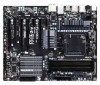
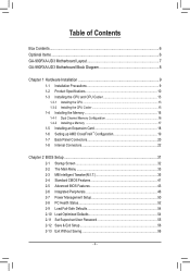
Table of Contents Box Contents...6 Optional Items...6 GA-990FXA-UD3 Motherboard Layout 7 GA-990FXA-UD3 Motherboard Block Diagram 8 Chapter 1 Hardware Installation 9 1-1 Installation Precautions 9 1-2 Product Specifications 10 1-3 Installing the CPU and CPU Cooler 13 1-3-1 Installing the CPU 13 1-3-2 Installing the CPU Cooler ...
Table of Contents Box Contents...6 Optional Items...6 GA-990FXA-UD3 Motherboard Layout 7 GA-990FXA-UD3 Motherboard Block Diagram 8 Chapter 1 Hardware Installation 9 1-1 Installation Precautions 9 1-2 Product Specifications 10 1-3 Installing the CPU and CPU Cooler 13 1-3-1 Installing the CPU 13 1-3-2 Installing the CPU Cooler ...
Manual
Page 6
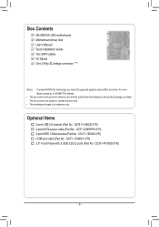
... 12CR1-FPX582-0*R) - 6 - Box Contents GA-990FXA-UD3 motherboard Motherboard driver disk User's Manual Quick Installation Guide Two SATA cables I/O Shield One 2-Way SLI bridge connector (Note) (Note ) To enable NVIDIA SLI technology, you obtain. For more details, please go to GIGABYTE's website. • The box contents above... are subject to change without notice. • The motherboard image is for reference only and the actual items shall depend on the product...
... 12CR1-FPX582-0*R) - 6 - Box Contents GA-990FXA-UD3 motherboard Motherboard driver disk User's Manual Quick Installation Guide Two SATA cables I/O Shield One 2-Way SLI bridge connector (Note) (Note ) To enable NVIDIA SLI technology, you obtain. For more details, please go to GIGABYTE's website. • The box contents above... are subject to change without notice. • The motherboard image is for reference only and the actual items shall depend on the product...
Manual
Page 8
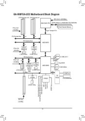
GA-990FXA-UD3 Motherboard Block Diagram 2 PCI Express x16 2 PCI Express x4 CPU CLK+/- (200 MHz) AM3+/AM3 CPU DDR3 2000(O.C.)/1866/1600/1333/1066 MHz PCIe CLK (100 ...
GA-990FXA-UD3 Motherboard Block Diagram 2 PCI Express x16 2 PCI Express x4 CPU CLK+/- (200 MHz) AM3+/AM3 CPU DDR3 2000(O.C.)/1866/1600/1333/1066 MHz PCIe CLK (100 ...
Manual
Page 9
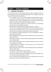
... have an ESD wrist strap, keep your hands dry and first touch a metal object to eliminate static electricity. • Prior to installing the motherboard, please have a problem related to the use of the product, please consult a certified computer technician. - 9 - Prior to installation, carefully ... the product, please verify that all cables and power connectors of your hardware components are connected. • To prevent damage to the motherboard, do not allow screws to come in a high-temperature environment. • Turning on the computer power during the installation process can become...
... have an ESD wrist strap, keep your hands dry and first touch a metal object to eliminate static electricity. • Prior to installing the motherboard, please have a problem related to the use of the product, please consult a certified computer technician. - 9 - Prior to installation, carefully ... the product, please verify that all cables and power connectors of your hardware components are connected. • To prevent damage to the motherboard, do not allow screws to come in a high-temperature environment. • Turning on the computer power during the installation process can become...

Manual
Page 12
... Center ŠŠ Support for Xpress Install ŠŠ Support for Xpress Recovery2 ŠŠ Support for EasyTune * Available functions in EasyTune may differ by motherboard model. ŠŠ Support for Easy Energy Saver ŠŠ Support for Smart Recovery ŠŠ Support for Auto Green ŠŠ Support for ON...
... Center ŠŠ Support for Xpress Install ŠŠ Support for Xpress Recovery2 ŠŠ Support for EasyTune * Available functions in EasyTune may differ by motherboard model. ŠŠ Support for Easy Energy Saver ŠŠ Support for Smart Recovery ŠŠ Support for Auto Green ŠŠ Support for ON...

Manual
Page 13
... standard requirements for the latest CPU support list.) • Always turn on the computer if the CPU cooler is not recommended that the motherboard supports the CPU. (Go to GIGABYTE's website for the peripherals. 1-3 Installing the CPU and CPU Cooler Read the following guidelines before you begin to install the CPU: •...
... standard requirements for the latest CPU support list.) • Always turn on the computer if the CPU cooler is not recommended that the motherboard supports the CPU. (Go to GIGABYTE's website for the peripherals. 1-3 Installing the CPU and CPU Cooler Read the following guidelines before you begin to install the CPU: •...
Manual
Page 14
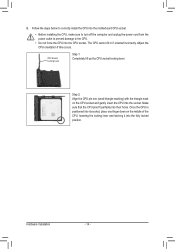
... middle of the CPU, lowering the locking lever and latching it into the socket. Follow the steps below to correctly install the CPU into the motherboard CPU socket. • Before installing the CPU, make sure to turn off the computer and unplug the power cord from the power outlet to prevent...
... middle of the CPU, lowering the locking lever and latching it into the socket. Follow the steps below to correctly install the CPU into the motherboard CPU socket. • Before installing the CPU, make sure to turn off the computer and unplug the power cord from the power outlet to prevent...
Manual
Page 15
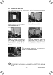
...CPU. On the other side,push straight down on the the CPU cooler clip to hook it to the CPU fan header (CPU_FAN) on the motherboard. Step 3: Hook the CPU cooler clip to the CPU. Use extreme care when removing the CPU cooler because the thermal grease/tape between the...CPU. - 15 - 1-3-2 Installing the CPU Cooler Follow the steps below to correctly install the CPU cooler on the CPU. (The following procedure uses the GIGABYTE cooler as the picture above shows) to lock into place. (Refer to your CPU cooler installation manual for instructions on installing the cooler.) Step 5: Finally...
...CPU. On the other side,push straight down on the the CPU cooler clip to hook it to the CPU fan header (CPU_FAN) on the motherboard. Step 3: Hook the CPU cooler clip to the CPU. Use extreme care when removing the CPU cooler because the thermal grease/tape between the...CPU. - 15 - 1-3-2 Installing the CPU Cooler Follow the steps below to correctly install the CPU cooler on the CPU. (The following procedure uses the GIGABYTE cooler as the picture above shows) to lock into place. (Refer to your CPU cooler installation manual for instructions on installing the cooler.) Step 5: Finally...
Manual
Page 16
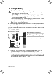
...power cord from the power outlet before installing the memory to insert the memory, switch the direction. 1-4-1 Dual Channel Memory Configuration This motherboard provides four DDR3 memory sockets and supports Dual Channel Technology. Enabling Dual Channel memory mode will automatically detect the specifications and capacity of...memory of the memory. DS/SS DDR3_3 - DS/SS DS/SS DDR3_1 DS/SS - Dual Channel mode cannot be used . (Go to GIGABYTE's website for optimum performance. After the memory is installed. 2. If you install them in the DDR3_1 and DDR3_2 sockets. DS/SS DS/...
...power cord from the power outlet before installing the memory to insert the memory, switch the direction. 1-4-1 Dual Channel Memory Configuration This motherboard provides four DDR3 memory sockets and supports Dual Channel Technology. Enabling Dual Channel memory mode will automatically detect the specifications and capacity of...memory of the memory. DS/SS DDR3_3 - DS/SS DS/SS DDR3_1 DS/SS - Dual Channel mode cannot be used . (Go to GIGABYTE's website for optimum performance. After the memory is installed. 2. If you install them in the DDR3_1 and DDR3_2 sockets. DS/SS DS/...

Manual
Page 17
Follow the steps below to install DDR3 DIMMs on this motherboard. As indicated in the picture on the memory and insert it can only fit in the memory sockets. Place the memory module on the top ...
Follow the steps below to install DDR3 DIMMs on this motherboard. As indicated in the picture on the memory and insert it can only fit in the memory sockets. Place the memory module on the top ...
Manual
Page 18
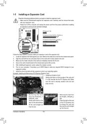
... the card until it is fully inserted into the slot. 4. If necessary, go to BIOS Setup to install an expansion card: • Make sure the motherboard supports the expansion card.
... the card until it is fully inserted into the slot. 4. If necessary, go to BIOS Setup to install an expansion card: • Make sure the motherboard supports the expansion card.
Manual
Page 19
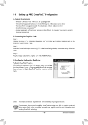
...(s) (Note) - A power supply with sufficient power is selected and click Apply. (Note) The bridge connector(s) may differ by graphics cards and driver version. A CrossFireX-supported motherboard with your graphics cards. Connecting the Graphics Cards Step 1: Observe the steps in the CrossFireX gold edge connectors on your graphics cards for enabling CrossFireX...
...(s) (Note) - A power supply with sufficient power is selected and click Apply. (Note) The bridge connector(s) may differ by graphics cards and driver version. A CrossFireX-supported motherboard with your graphics cards. Connecting the Graphics Cards Step 1: Observe the steps in the CrossFireX gold edge connectors on your graphics cards for enabling CrossFireX...
Manual
Page 20
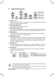
... 2.0/1.1 specification. Optical S/PDIF Out Connector This connector provides digital audio out to an external audio system that your device and then remove it from the motherboard. •• When removing the cable, pull it side to side to prevent an electrical short inside the cable connector. eSATA 6Gb/s Connector The eSATA...
... 2.0/1.1 specification. Optical S/PDIF Out Connector This connector provides digital audio out to an external audio system that your device and then remove it from the motherboard. •• When removing the cable, pull it side to side to prevent an electrical short inside the cable connector. eSATA 6Gb/s Connector The eSATA...

Manual
Page 22
..., make sure your devices are compliant with the connectors you wish to connect. • Before installing the devices, be sure to the connector on the motherboard. Hardware Installation - 22 - Unplug the power cord from the power outlet to prevent damage to the devices. • After installing the device and before connecting...
..., make sure your devices are compliant with the connectors you wish to connect. • Before installing the devices, be sure to the connector on the motherboard. Hardware Installation - 22 - Unplug the power cord from the power outlet to prevent damage to the devices. • After installing the device and before connecting...
Manual
Page 23
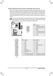
... power connector mainly supplies power to the power connector in the correct orientation. If a power supply is turned off and all the components on the motherboard. If the 12V power connector is recommended that a power supply that does not provide the required power, the result can supply enough stable power to...
... power connector mainly supplies power to the power connector in the correct orientation. If a power supply is turned off and all the components on the motherboard. If the 12V power connector is recommended that a power supply that does not provide the required power, the result can supply enough stable power to...
Manual
Page 24
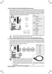
The motherboard supports CPU fan speed control, which requires the use of hard drives does not have to the CPU or the system may result in the ... 1, RAID 5, RAID 10, and JBOD. SATA3_0 7 7 SATA3_1 G.QBOFM G.QBOFM SATA3_2 SATA3_3 SATA3_4 1 1 SATA3_5 PGin.NQBoO. CPU_FAN: Pin No. 3/4/5) CPU_FAN/SYS_FAN1/SYS_FAN2/PWR_FAN (Fan Headers) The motherboard has a 4-pin CPU fan header (CPU_FAN), a 3-pin (SYS_FAN2) and a 4-pin (SYS_ FAN1) system fan headers, and a 3-pin power fan header (PWR_FAN).
The motherboard supports CPU fan speed control, which requires the use of hard drives does not have to the CPU or the system may result in the ... 1, RAID 5, RAID 10, and JBOD. SATA3_0 7 7 SATA3_1 G.QBOFM G.QBOFM SATA3_2 SATA3_3 SATA3_4 1 1 SATA3_5 PGin.NQBoO. CPU_FAN: Pin No. 3/4/5) CPU_FAN/SYS_FAN1/SYS_FAN2/PWR_FAN (Fan Headers) The motherboard has a 4-pin CPU fan header (CPU_FAN), a 3-pin (SYS_FAN2) and a 4-pin (SYS_ FAN1) system fan headers, and a 3-pin power fan header (PWR_FAN).
Manual
Page 26
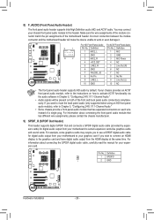
...assignments of a single plug. Definition Pin No. For information about connecting the S/PDIF digital audio cable, carefully read the manual for your motherboard to work or even damage it. You may require you want to mute the back panel audio (only supported when using an HD front... an AC'97 front panel audio module, refer to the instructions on each wire instead of the motherboard header. Pin No. Incorrect connection between the module connector and the motherboard header will be present on both of the front and back panel audio connections simultane- Definition F_1PANEL(...
...assignments of a single plug. Definition Pin No. For information about connecting the S/PDIF digital audio cable, carefully read the manual for your motherboard to work or even damage it. You may require you want to mute the back panel audio (only supported when using an HD front... an AC'97 front panel audio module, refer to the instructions on each wire instead of the motherboard header. Pin No. Incorrect connection between the module connector and the motherboard header will be present on both of the front and back panel audio connections simultane- Definition F_1PANEL(...
Manual
Page 29
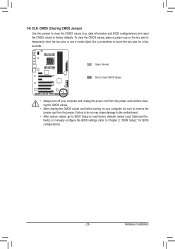
Failure to do so may cause damage to the motherboard. •• After system restart, go to BIOS Setup to load factory defaults (select Load Optimized Defaults) or manually configure the BIOS settings (refer to ...
Failure to do so may cause damage to the motherboard. •• After system restart, go to BIOS Setup to load factory defaults (select Load Optimized Defaults) or manually configure the BIOS settings (refer to ...
Manual
Page 31
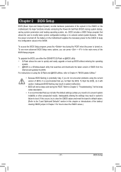
...BIOS, do not encounter problems using the Q-Flash and @BIOS utilities, refer to activate certain system features. To upgrade the BIOS, use either the GIGABYTE Q-Flash or @BIOS utility. • Q-Flash allows the user to quickly and easily upgrade or back up BIOS without entering the operating system. ... the Power-On Self-Test (POST) during the POST when the power is turned on the motherboard supplies the necessary power to the CMOS to boot. For instructions on the motherboard. Inadequately altering the settings may result in system's failure to keep the configuration values in the ...
...BIOS, do not encounter problems using the Q-Flash and @BIOS utilities, refer to activate certain system features. To upgrade the BIOS, use either the GIGABYTE Q-Flash or @BIOS utility. • Q-Flash allows the user to quickly and easily upgrade or back up BIOS without entering the operating system. ... the Power-On Self-Test (POST) during the POST when the power is turned on the motherboard supplies the necessary power to the CMOS to boot. For instructions on the motherboard. Inadequately altering the settings may result in system's failure to keep the configuration values in the ...


