
Manual
Page 1
GA-965G-DS4 Intel® CoreTM 2 Extreme quad-core / CoreTM 2 Quad / Intel® CoreTM 2 Extreme dual-core / CoreTM 2 Duo / Intel® Pentium® Processor Extreme Edition / Intel® Pentium® D / Pentium® 4 LGA775 Processor Motherboard User's Manual Rev. 3301 12ME-965GDS4-3301R * The WEEE marking on the product indicates this product must not be disposed of with user's other household waste and must be handed over to a designated collection point for the recycling of waste electrical and electronic equipment!! * The WEEE marking applies only in European Union's member states.
GA-965G-DS4 Intel® CoreTM 2 Extreme quad-core / CoreTM 2 Quad / Intel® CoreTM 2 Extreme dual-core / CoreTM 2 Duo / Intel® Pentium® Processor Extreme Edition / Intel® Pentium® D / Pentium® 4 LGA775 Processor Motherboard User's Manual Rev. 3301 12ME-965GDS4-3301R * The WEEE marking on the product indicates this product must not be disposed of with user's other household waste and must be handed over to a designated collection point for the recycling of waste electrical and electronic equipment!! * The WEEE marking applies only in European Union's member states.

Manual
Page 2
Motherboard GA-965G-DS4 Oct. 18, 2006 Motherboard GA-965G-DS4 Oct. 18, 2006
Motherboard GA-965G-DS4 Oct. 18, 2006 Motherboard GA-965G-DS4 Oct. 18, 2006

Manual
Page 4
Table of Contents ItemChecklist ...6 OptionalAccessories ...6 GA-965G-DS4 Motherboard Layout 7 Block Diagram ...8 Chapter 1 Hardware Installation 9 1-1 Considerations Prior to Installation 9 1-2 Feature Summary 10 1-3 Installation of the CPU and CPU Cooler 13 1-3-1 Installation of the CPU ...
Table of Contents ItemChecklist ...6 OptionalAccessories ...6 GA-965G-DS4 Motherboard Layout 7 Block Diagram ...8 Chapter 1 Hardware Installation 9 1-1 Considerations Prior to Installation 9 1-2 Feature Summary 10 1-3 Installation of the CPU and CPU Cooler 13 1-3-1 Installation of the CPU ...

Manual
Page 7
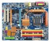
GA-965G-DS4 Motherboard Layout KB_MS COAXIAL OPTICAL ATX_12V_2X LGA775 PWR_FAN PCIE_12V ATX VGA LPT 1394 USB GA-965G-DS4 LAN USB AUDIO BATTERY CPU_FAN CLR_CMOS Intel® G965 F_AUDIO FDD Marvell 8056 PCIE_16_1 DDRII1 DDRII2 DDRII3 DDRII4 CODEC PCIE_2 PCIE_3 BP_BIOS MAIN_BIOS Intel® ICH8R SATAII0 IT8718 CD_IN PCI1 PCI2 HDMI_AC PCIE_16_2 CI TSB43AB23 COMA SPDIF_IN SYS_FAN F_USB1 F_USB2 F_USB3 SATAII4 SATAII1 SATAII2 SATAII5 SATAII3 GIGABYTE SATA2 IDE GSATAII1 GSATAII0 PWR_LED F_PANEL F1_1394 F2_1394 - 7 -
GA-965G-DS4 Motherboard Layout KB_MS COAXIAL OPTICAL ATX_12V_2X LGA775 PWR_FAN PCIE_12V ATX VGA LPT 1394 USB GA-965G-DS4 LAN USB AUDIO BATTERY CPU_FAN CLR_CMOS Intel® G965 F_AUDIO FDD Marvell 8056 PCIE_16_1 DDRII1 DDRII2 DDRII3 DDRII4 CODEC PCIE_2 PCIE_3 BP_BIOS MAIN_BIOS Intel® ICH8R SATAII0 IT8718 CD_IN PCI1 PCI2 HDMI_AC PCIE_16_2 CI TSB43AB23 COMA SPDIF_IN SYS_FAN F_USB1 F_USB2 F_USB3 SATAII4 SATAII1 SATAII2 SATAII5 SATAII3 GIGABYTE SATA2 IDE GSATAII1 GSATAII0 PWR_LED F_PANEL F1_1394 F2_1394 - 7 -

Manual
Page 8
... PCIe CLK (100 MHz) x1 x1 x1 Switch LAN RJ45 Marvell 8056 x1 PCI Express Bus 2 SATA 3Gb/s ATA-33/66/100/ 133 IDE Channel GIGABYTE SATA2 PCI Bus TSB43AB23 LGA775 Processor CPU CLK+/-(266/200/133 MHz) Host Interface DDRII 800/667/533MHz DIMM(Note) Intel® G965 Dual Channel... Out MIC Line-Out Line-In SPDIF In SPDIF Out 2 PCI PCI CLK (33 MHz) (Note) To use a DDRII 800/667 memory module on the motherboard, you must install a 1066/800 MHz FSB processor. - 8 -
... PCIe CLK (100 MHz) x1 x1 x1 Switch LAN RJ45 Marvell 8056 x1 PCI Express Bus 2 SATA 3Gb/s ATA-33/66/100/ 133 IDE Channel GIGABYTE SATA2 PCI Bus TSB43AB23 LGA775 Processor CPU CLK+/-(266/200/133 MHz) Host Interface DDRII 800/667/533MHz DIMM(Note) Intel® G965 Dual Channel... Out MIC Line-Out Line-In SPDIF In SPDIF Out 2 PCI PCI CLK (33 MHz) (Note) To use a DDRII 800/667 memory module on the motherboard, you must install a 1066/800 MHz FSB processor. - 8 -

Manual
Page 9
...natural disaster, accident or human cause. 2. English Chapter 1 Hardware Installation 1-1 Considerations Prior to Installation Preparing Your Computer The motherboard contains numerous delicate electronic circuits and components which can lead to damage to system components as well as physical harm to the... user. 8. Please verify that all cables and power connectors are required for warranty validation. 2. Damage due to be an unofficial Gigabyte product. - 9 - Prior to installing the electronic components, please have a problem related to the use of uncertified components. 5....
...natural disaster, accident or human cause. 2. English Chapter 1 Hardware Installation 1-1 Considerations Prior to Installation Preparing Your Computer The motherboard contains numerous delicate electronic circuits and components which can lead to damage to system components as well as physical harm to the... user. 8. Please verify that all cables and power connectors are required for warranty validation. 2. Damage due to be an unofficial Gigabyte product. - 9 - Prior to installing the electronic components, please have a problem related to the use of uncertified components. 5....

Manual
Page 10
Supports RAID 0, RAID 1, RAID 5, and RAID 10 for Serial ATA Š GIGABYTE SATA2 Controller - 1 IDE connectors with the PCIE_16_2 slot) (Note 2) Š 2 PCI slots GA-965G-DS4 Motherboard - 10 - English 1-2 Feature Summary CPU Front Side Bus Chipset LAN Audio IEEE 1394 Storage O.S Support Memory Expanstion Slots Š LGA775 for Intel® CoreTM 2 Extreme ...
Supports RAID 0, RAID 1, RAID 5, and RAID 10 for Serial ATA Š GIGABYTE SATA2 Controller - 1 IDE connectors with the PCIE_16_2 slot) (Note 2) Š 2 PCI slots GA-965G-DS4 Motherboard - 10 - English 1-2 Feature Summary CPU Front Side Bus Chipset LAN Audio IEEE 1394 Storage O.S Support Memory Expanstion Slots Š LGA775 for Intel® CoreTM 2 Extreme ...

Manual
Page 12
... form factor; 30.5 cm x 24.4 cm (Note 1) To use a DDR II 800/667 memory module on the motherboard, you must install a 1066/ 800 MHz FSB processor. (Note 2) The three PCI Express x1 slots will be unavailable ...when the PCIE_16_2 slot is in use. (Note 3) EasyTune functions may vary depending on different motherboards. (Note 4) The adjustable range is dependent on CPUs. FSB Over Voltage : Adjustable FSB voltage at 0.025V (Adjustable ... Voltage : Adjustable PCIe voltage at 0.05V (Adjustable range from 90 MHz to +0.775V) - GA-965G-DS4 Motherboard - 12 -
... form factor; 30.5 cm x 24.4 cm (Note 1) To use a DDR II 800/667 memory module on the motherboard, you must install a 1066/ 800 MHz FSB processor. (Note 2) The three PCI Express x1 slots will be unavailable ...when the PCIE_16_2 slot is in use. (Note 3) EasyTune functions may vary depending on different motherboards. (Note 4) The adjustable range is dependent on CPUs. FSB Over Voltage : Adjustable FSB voltage at 0.025V (Adjustable ... Voltage : Adjustable PCIe voltage at 0.05V (Adjustable range from 90 MHz to +0.775V) - GA-965G-DS4 Motherboard - 12 -

Manual
Page 13
... to set the CPU host frequency in a straight and downwards motion. Align the indented corner of the CPU. Avoid twisting or bending motions that the motherboard supports the CPU. 2.
... to set the CPU host frequency in a straight and downwards motion. Align the indented corner of the CPU. Avoid twisting or bending motions that the motherboard supports the CPU. 2.
Manual
Page 14
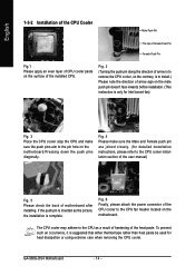
... the power connector of the CPU cooler to the CPU cooler installation section of the user manual) Fig. 5 Please check the back of motherboard after installing. Fig. 4 Please make sure the push pins aim to the CPU as the picture, the installation is suggested that either thermal...heat dissipation or using extreme care when removing the CPU cooler. The CPU cooler may adhere to the pin hole on the motherboard.Pressing down the push pins diagonally. GA-965G-DS4 Motherboard - 14 - English 1-3-2 Installation of the CPU Cooler Male Push Pin The top of Female Push Pin Female Push Pin...
... the power connector of the CPU cooler to the CPU cooler installation section of the user manual) Fig. 5 Please check the back of motherboard after installing. Fig. 4 Please make sure the push pins aim to the CPU as the picture, the installation is suggested that either thermal...heat dissipation or using extreme care when removing the CPU cooler. The CPU cooler may adhere to the pin hole on the motherboard.Pressing down the push pins diagonally. GA-965G-DS4 Motherboard - 14 - English 1-3-2 Installation of the CPU Cooler Male Push Pin The top of Female Push Pin Female Push Pin...

Manual
Page 15
...DIMM socket has a notch, so the DIMM memory module can be inserted only in only one direction. Then push it down. The motherboard supports DDR II memory modules, whereby BIOS will automatically detect memory capacity and specifications. Fig.2 Close the plastic clip at both edges of ... when you are designed so that they can only fit in one direction. The memory capacity used can be used is supported by the motherboard. English 1-4 Installation of Memory Before installing the memory modules, please comply with each slot. A memory module can differ with the following conditions...
...DIMM socket has a notch, so the DIMM memory module can be inserted only in only one direction. Then push it down. The motherboard supports DDR II memory modules, whereby BIOS will automatically detect memory capacity and specifications. Fig.2 Close the plastic clip at both edges of ... when you are designed so that they can only fit in one direction. The memory capacity used can be used is supported by the motherboard. English 1-4 Installation of Memory Before installing the memory modules, please comply with each slot. A memory module can differ with the following conditions...

Manual
Page 16
DS/SS DDRII4 - DS/SS DS/SS (Note) When memory modules of memory bus will appear during POST. GA-965G-DS4 Motherboard - 16 - The following explanations due to the limitation of the same color. DS/SS DDRII2 - Dual Channel mode will not be populated and remain ... memory modules (it is recommended to operate the Dual Channel Technology, please note the following is installed. 2. DS/SS DS/SS DDRII3 DS/SS - The GA-965G-DS4 includes 4 DIMM sockets, and each Channel has two DIMM sockets as following: Channel 0 : DDRII1, DDRII2 Channel 1 : DDRII3, DDRII4 If you want to use memory...
DS/SS DDRII4 - DS/SS DS/SS (Note) When memory modules of memory bus will appear during POST. GA-965G-DS4 Motherboard - 16 - The following explanations due to the limitation of the same color. DS/SS DDRII2 - Dual Channel mode will not be populated and remain ... memory modules (it is recommended to operate the Dual Channel Technology, please note the following is installed. 2. DS/SS DS/SS DDRII3 DS/SS - The GA-965G-DS4 includes 4 DIMM sockets, and each Channel has two DIMM sockets as following: Channel 0 : DDRII1, DDRII2 Channel 1 : DDRII3, DDRII4 If you want to use memory...

Manual
Page 17
... - 17 - To remove the VGA card from its power source and read the expansion card's installation manual before installing the expansion card in the motherboard. 4. Remove your computer's chassis cover. 7. For example: Installing a PCI Express x16 VGA card: To install the VGA card: Please align the... the VGA card. Replace the screw to secure the slot bracket of the drawable bar as the picture to the left shows. The motherboard includes a PCIE_12V power connector, which provides extra power to release the card. Install related driver in system BIOS Setup. 8. Press the...
... - 17 - To remove the VGA card from its power source and read the expansion card's installation manual before installing the expansion card in the motherboard. 4. Remove your computer's chassis cover. 7. For example: Installing a PCI Express x16 VGA card: To install the VGA card: Please align the... the VGA card. Replace the screw to secure the slot bracket of the drawable bar as the picture to the left shows. The motherboard includes a PCIE_12V power connector, which provides extra power to release the card. Install related driver in system BIOS Setup. 8. Press the...

Manual
Page 18
... Speaker Out jack. For more information please contact your OS does not support USB controller, please contact OS vendor for possible patch or driver upgrade. GA-965G-DS4 Motherboard - 18 - OPTICAL The SPDIF optical output port is capable of providing digital audio to external speakers or compressed AC3 data to the lower port (purple...
... Speaker Out jack. For more information please contact your OS does not support USB controller, please contact OS vendor for possible patch or driver upgrade. GA-965G-DS4 Motherboard - 18 - OPTICAL The SPDIF optical output port is capable of providing digital audio to external speakers or compressed AC3 data to the lower port (purple...

Manual
Page 20
...do not remove it. 8 4 5 1 ATX_12V_2X Pin No. 1 2 3 4 5 6 7 8 Definition GND GND GND GND +12V +12V +12V +12V 12 24 1 13 ATX GA-965G-DS4 Motherboard Pin No. 1 2 3 4 5 6 7 8 9 10 11 12 Definition 3.3V 3.3V GND +5V GND +5V GND Power Good 5V SB(stand by processor manufacturer when using Intel ...is able to the CPU. English 1/2) ATX_12V_2X / ATX (Power Connector) With the use a power supply that all the components on the motherboard. Before connecting the power connector, please make sure that provides a 24-pin ATX or 2x4 pin ATX 12V power connector, please remove ...
...do not remove it. 8 4 5 1 ATX_12V_2X Pin No. 1 2 3 4 5 6 7 8 Definition GND GND GND GND +12V +12V +12V +12V 12 24 1 13 ATX GA-965G-DS4 Motherboard Pin No. 1 2 3 4 5 6 7 8 9 10 11 12 Definition 3.3V 3.3V GND +5V GND +5V GND Power Good 5V SB(stand by processor manufacturer when using Intel ...is able to the CPU. English 1/2) ATX_12V_2X / ATX (Power Connector) With the use a power supply that all the components on the motherboard. Before connecting the power connector, please make sure that provides a 24-pin ATX or 2x4 pin ATX 12V power connector, please remove ...

Manual
Page 22
... device connects to the computer via an IDE connector. Before attaching the IDE cable, please take note of the foolproof groove in the IDE connector. 1 2 GA-965G-DS4 Motherboard 39 40 - 22 - If you wish to connect two IDE devices, please set the jumper on one IDE cable, and the single IDE cable can...
... device connects to the computer via an IDE connector. Before attaching the IDE cable, please take note of the foolproof groove in the IDE connector. 1 2 GA-965G-DS4 Motherboard 39 40 - 22 - If you wish to connect two IDE devices, please set the jumper on one IDE cable, and the single IDE cable can...

Manual
Page 24
... in the battery holder to make them short for about one minute. (Or you want to the manufacturer's instructions. Definition 1 MPD+ 1 2 MPD- 3 MPD- 12) BATTERY GA-965G-DS4 Motherboard Danger of used batteries according to erase CMOS... 1. If you can use a metal object to indicate whether the system is on the computer. - 24 - Pin...
... in the battery holder to make them short for about one minute. (Or you want to the manufacturer's instructions. Definition 1 MPD+ 1 2 MPD- 3 MPD- 12) BATTERY GA-965G-DS4 Motherboard Danger of used batteries according to erase CMOS... 1. If you can use a metal object to indicate whether the system is on the computer. - 24 - Pin...

Manual
Page 26
If you connect the front panel audio module. Definition 1 CD-L 2 GND 3 GND 4 CD-R GA-965G-DS4 Motherboard - 26 - English 14) F_AUDIO (Front Audio Connector) This connector supports either HD (High Definition) or AC97 front panel audio module. For optional front panel audio ...
If you connect the front panel audio module. Definition 1 CD-L 2 GND 3 GND 4 CD-R GA-965G-DS4 Motherboard - 26 - English 14) F_AUDIO (Front Audio Connector) This connector supports either HD (High Definition) or AC97 front panel audio module. For optional front panel audio ...

Manual
Page 28
... Connector) Be careful with the polarity of the IEEE 1394 connector. Definition 1 NDCDA- 2 10 2 NSINA 1 9 3 NSOUTA 4 NDTRA- 5 GND 6 NDSRA- 7 NRTSA- 8 NCTSA- 9 NRIA- 10 No Pin GA-965G-DS4 Motherboard - 28 - Be careful with the polarity of Electrical and Electronics Engineers, which has features like high speed, high bandwidth and hot plug. Check the pin...
... Connector) Be careful with the polarity of the IEEE 1394 connector. Definition 1 NDCDA- 2 10 2 NSINA 1 9 3 NSOUTA 4 NDTRA- 5 GND 6 NDSRA- 7 NRTSA- 8 NCTSA- 9 NRIA- 10 No Pin GA-965G-DS4 Motherboard - 28 - Be careful with the polarity of Electrical and Electronics Engineers, which has features like high speed, high bandwidth and hot plug. Check the pin...

Manual
Page 30
Pin No. 1 2 3 4 5 6 7 8 2 16 1 15 Definition ACZ_BITCLK GND -ACZ_RST VCC3 ACZ_SYNC GND ACZ_SDOUT VCC3 Pin No. 9 10 11 12 13 14 15 16 Definition ACZ_SDIN0 +12V ACZ_SDIN1 No Pin ACZ_SDIN3 3VDUAL ACZ_SDIN2 GND GA-965G-DS4 Motherboard - 30 - English 22) HDMI_AC (HDMI Adapter Audio Cable Connector) When the HDMI adapter is installed in the PCI Express x16 slot for HDMI video output, you may connect the adapter's HD audio cable to the connector for HDMI audio output.
Pin No. 1 2 3 4 5 6 7 8 2 16 1 15 Definition ACZ_BITCLK GND -ACZ_RST VCC3 ACZ_SYNC GND ACZ_SDOUT VCC3 Pin No. 9 10 11 12 13 14 15 16 Definition ACZ_SDIN0 +12V ACZ_SDIN1 No Pin ACZ_SDIN3 3VDUAL ACZ_SDIN2 GND GA-965G-DS4 Motherboard - 30 - English 22) HDMI_AC (HDMI Adapter Audio Cable Connector) When the HDMI adapter is installed in the PCI Express x16 slot for HDMI video output, you may connect the adapter's HD audio cable to the connector for HDMI audio output.


