Manual
Page 4
Table of Contents Box Contents ...6 OptionalItems ...6 GA-945PL-S3G Motherboard Layout 7 Block Diagram ...8 Chapter 1 Hardware Installation 9 1-1 Installation Precautions 9 1-2 Product Specifications 10 1-3 Installing the CPU and CPU Cooler 13 ... Memory 17 1-5 Installing an Expansion Card 18 1-6 Back Panel Connectors 19 1-7 Internal Connectors 20 Chapter 2 BIOS Setup 29 2-1 Startup Screen 30 2-2 The Main Menu 31 2-3 Standard CMOS Features 33 2-4 Advanced BIOS Features 35 2-5 IntegratedPeripherals 37 2-6 Power Management Setup 40 2-7 PnP/PCI Configurations 42 2-8 PC Health Status...
Table of Contents Box Contents ...6 OptionalItems ...6 GA-945PL-S3G Motherboard Layout 7 Block Diagram ...8 Chapter 1 Hardware Installation 9 1-1 Installation Precautions 9 1-2 Product Specifications 10 1-3 Installing the CPU and CPU Cooler 13 ... Memory 17 1-5 Installing an Expansion Card 18 1-6 Back Panel Connectors 19 1-7 Internal Connectors 20 Chapter 2 BIOS Setup 29 2-1 Startup Screen 30 2-2 The Main Menu 31 2-3 Standard CMOS Features 33 2-4 Advanced BIOS Features 35 2-5 IntegratedPeripherals 37 2-6 Power Management Setup 40 2-7 PnP/PCI Configurations 42 2-8 PC Health Status...

Manual
Page 11
Hardware Installation Internal Connectors Š 1 x 24-pin ATX main power connector Š 1 x 4-pin ATX 12V power connector Š 1 x floppy disk drive connector Š 1 x IDE connector Š 4 x SATA 3Gb/s connectors Š 1 x CPU fan header Š 1 x ...
Hardware Installation Internal Connectors Š 1 x 24-pin ATX main power connector Š 1 x 4-pin ATX 12V power connector Š 1 x floppy disk drive connector Š 1 x IDE connector Š 4 x SATA 3Gb/s connectors Š 1 x CPU fan header Š 1 x ...

Manual
Page 21
... a power supply is used that can withstand high power consumption be used (400W or greater). 1/2) ATX_12V/ATX (2x2 12V Power Connector and 2x12 Main Power Connector) With the use of the power connector, the power supply can lead to an unstable or unbootable system. • The... Do not insert the power supply cable into pins under the protective cover when using a 2x12 power supply, remove the protective cover from the main power connector on the motherboard. The power connector possesses a foolproof design. Connect the power supply cable to the CPU. If the 12V power ...
... a power supply is used that can withstand high power consumption be used (400W or greater). 1/2) ATX_12V/ATX (2x2 12V Power Connector and 2x12 Main Power Connector) With the use of the power connector, the power supply can lead to an unstable or unbootable system. • The... Do not insert the power supply cable into pins under the protective cover when using a 2x12 power supply, remove the protective cover from the main power connector on the motherboard. The power connector possesses a foolproof design. Connect the power supply cable to the CPU. If the 12V power ...

Manual
Page 25
... the speaker on the chassis front panel. One single short beep will be heard if no problem is in S1 sleep state. A front panel module mainly consists of power switch, reset switch, power LED, hard drive activity LED, speaker and etc. The LED is on when the hard drive is reading...
... the speaker on the chassis front panel. One single short beep will be heard if no problem is in S1 sleep state. A front panel module mainly consists of power switch, reset switch, power LED, hard drive activity LED, speaker and etc. The LED is on when the hard drive is reading...
Manual
Page 29
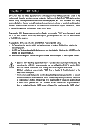
...certain system features. Refer to Chapter 5, "Troubleshooting," for how to clear the CMOS values.) - 29 - BIOS Setup To upgrade the BIOS, use either the GIGABYTE Q-Flash or @BIOS utility. • Q-Flash allows the user to quickly and easily upgrade or back up BIOS without entering the operating system. • ...potentially risky, if you do it is a Windows-based utility that you not alter the default settings (unless you can press + in the main menu of BIOS from the Internet and updates the BIOS. If this occurs, try to clear the CMOS values and reset the board to ...
...certain system features. Refer to Chapter 5, "Troubleshooting," for how to clear the CMOS values.) - 29 - BIOS Setup To upgrade the BIOS, use either the GIGABYTE Q-Flash or @BIOS utility. • Q-Flash allows the user to quickly and easily upgrade or back up BIOS without entering the operating system. • ...potentially risky, if you do it is a Windows-based utility that you not alter the default settings (unless you can press + in the main menu of BIOS from the Internet and updates the BIOS. If this occurs, try to clear the CMOS values and reset the board to ...

Manual
Page 31
...Item Help block on the right side of the submenu. • If you do not find the settings you enter the BIOS Setup program, the Main Menu (as usual, select the Load Optimized Defaults item to set your system to its defaults. • The BIOS Setup menus described in a submenu..., Hard Disk Type... BIOS Setup BIOS Setup Program Function Keys Move the selection bar to select an item Execute command or enter the submenu Main Menu: Exit the BIOS Setup program Submenus: Exit current submenu Increase the numeric value or make changes Decrease the numeric value or make changes ...
...Item Help block on the right side of the submenu. • If you do not find the settings you enter the BIOS Setup program, the Main Menu (as usual, select the Load Optimized Defaults item to set your system to its defaults. • The BIOS Setup menus described in a submenu..., Hard Disk Type... BIOS Setup BIOS Setup Program Function Keys Move the selection bar to select an item Execute command or enter the submenu Main Menu: Exit the BIOS Setup program Submenus: Exit current submenu Increase the numeric value or make changes Decrease the numeric value or make changes ...
Manual
Page 35
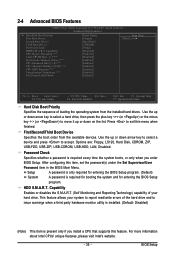
... down arrow key to select a device and press to exit this item, set the password(s) under the Set Supervisor/User Password item in the BIOS Main Menu. BIOS Setup
... down arrow key to select a device and press to exit this item, set the password(s) under the Set Supervisor/User Password item in the BIOS Main Menu. BIOS Setup

Manual
Page 49
... the CMOS. This exits the BIOS Setup without saving the changes made in BIOS Setup to the BIOS Setup Main Menu. - 49 - BIOS Setup Press or to return to the BIOS Setup Main Menu. 2-14 Exit Without Saving CMOS Setup Utility-Copyright (C) 1984-2007 Award Software ` Standard CMOS Features Load Fail-Safe...
... the CMOS. This exits the BIOS Setup without saving the changes made in BIOS Setup to the BIOS Setup Main Menu. - 49 - BIOS Setup Press or to return to the BIOS Setup Main Menu. 2-14 Exit Without Saving CMOS Setup Utility-Copyright (C) 1984-2007 Award Software ` Standard CMOS Features Load Fail-Safe...

Manual
Page 61
... BIOS. Step 1: 1. Step 2: The process of Q-Flash, use the up or down arrow key to select Update BIOS from Drive and press . • The Save Main BIOS to Drive option allows you to save the BIOS file to a floppy disk. Save BIOS to Drive PleKaLse:Mproevses any key to return to... a hard drive in RAID/AHCI mode or a hard drive attached to an independent IDE/SATA controller, use the key during the POST to the main menu. In the main menu of the system reading the BIOS file from Drive Sa0vefilBeI(Os)SfotounDdrive KL:Move ESC:Reset :Power Off Total size : 0 Free size...
... BIOS. Step 1: 1. Step 2: The process of Q-Flash, use the up or down arrow key to select Update BIOS from Drive and press . • The Save Main BIOS to Drive option allows you to save the BIOS file to a floppy disk. Save BIOS to Drive PleKaLse:Mproevses any key to return to... a hard drive in RAID/AHCI mode or a hard drive attached to an independent IDE/SATA controller, use the key during the POST to the main menu. In the main menu of the system reading the BIOS file from Drive Sa0vefilBeI(Os)SfotounDdrive KL:Move ESC:Reset :Power Off Total size : 0 Free size...
Manual
Page 63
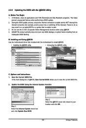
...BIOS utility. • Accessing the @BIOS utility. Do not use the C.O.M. (Corporate Online Management) function when using @BIOS. 4. Click Start>All Programs>GIGABYTE> @BIOS>@BIOS C. During the BIOS update process, ensure the Internet connection is stable and do so may result in a corrupted BIOS or a system that... file. 2. Installing and Using @BIOS: Use the motherboard driver disk included with the @BIOS Utility A. Save the Current BIOS File In the main dialog box of @BIOS, Save Current BIOS allows you to your location and click OK. - 63 - Before You Begin: 1. In Windows,...
...BIOS utility. • Accessing the @BIOS utility. Do not use the C.O.M. (Corporate Online Management) function when using @BIOS. 4. Click Start>All Programs>GIGABYTE> @BIOS>@BIOS C. During the BIOS update process, ensure the Internet connection is stable and do so may result in a corrupted BIOS or a system that... file. 2. Installing and Using @BIOS: Use the motherboard driver disk included with the @BIOS Utility A. Save the Current BIOS File In the main dialog box of @BIOS, Save Current BIOS allows you to your location and click OK. - 63 - Before You Begin: 1. In Windows,...
Manual
Page 75
...on the CLR_CMOS jumper in Chapter 1. If your motherboard, please go to enter BIOS Setup. A: Make sure your computer. Q: Why is still on GIGABYTE's website. Select "Load Fail-Safe Defaults" (or "Load Optimized Defaults") to restart your speaker is equipped with power/ amplifier. Replace the battery. 4....: Graphics card not inserted properly Continuous short beeps: Power error - 75 - Refer to show the advanced options. In the Main Menu, press + to the steps below: Steps: 1. Press to the Support\Motherboard\FAQ page on . If not, try a speaker with an ...
...on the CLR_CMOS jumper in Chapter 1. If your motherboard, please go to enter BIOS Setup. A: Make sure your computer. Q: Why is still on GIGABYTE's website. Select "Load Fail-Safe Defaults" (or "Load Optimized Defaults") to restart your speaker is equipped with power/ amplifier. Replace the battery. 4....: Graphics card not inserted properly Continuous short beeps: Power error - 75 - Refer to show the advanced options. In the Main Menu, press + to the steps below: Steps: 1. Press to the Support\Motherboard\FAQ page on . If not, try a speaker with an ...

Manual
Page 76
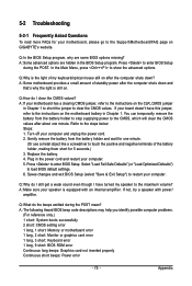
Is the power connector of the CPU cooler connected to enter BIOS Setup. Connect the ATX main power cable and the 12V power cable. Secure the CPU No cooler on the power to the motherboard. The problem is attached to the CPU ... changes and exit BIOS Setup. START Turn off the power. Remove all peripherals, connecting cables, and power cord etc. Yes Insert the graphics card. A (Continued...) GA-945PL-S3G Motherboard - 76 -
Is the power connector of the CPU cooler connected to enter BIOS Setup. Connect the ATX main power cable and the 12V power cable. Secure the CPU No cooler on the power to the motherboard. The problem is attached to the CPU ... changes and exit BIOS Setup. START Turn off the power. Remove all peripherals, connecting cables, and power cord etc. Yes Insert the graphics card. A (Continued...) GA-945PL-S3G Motherboard - 76 -