
Manual
Page 4
...GA-945GZM-S2 Motherboard Layout 7 Block Diagram ...8 Chapter 1 Hardware Installation 9 1-1 Considerations Prior to Installation 9 1-2 Feature Summary 10 1-3 Installation of the CPU and CPU Cooler 12 1-3-1 Installation of the CPU 12 1-3-2 Installation of the CPU Cooler 13 1-4 Installation of Memory 14 1-5 Installation of Expansion Cards 15 1-6 I/O Back Panel Introduction 17 1-7 Connectors Introduction 18 Chapter 2 BIOS... Setup 29 The Main Menu (For example: BIOS Ver. : FHa 30 2-1 Standard CMOS Features 32 2-2 Advanced BIOS Features 34 2-3 ...
...GA-945GZM-S2 Motherboard Layout 7 Block Diagram ...8 Chapter 1 Hardware Installation 9 1-1 Considerations Prior to Installation 9 1-2 Feature Summary 10 1-3 Installation of the CPU and CPU Cooler 12 1-3-1 Installation of the CPU 12 1-3-2 Installation of the CPU Cooler 13 1-4 Installation of Memory 14 1-5 Installation of Expansion Cards 15 1-6 I/O Back Panel Introduction 17 1-7 Connectors Introduction 18 Chapter 2 BIOS... Setup 29 The Main Menu (For example: BIOS Ver. : FHa 30 2-1 Standard CMOS Features 32 2-2 Advanced BIOS Features 34 2-3 ...
Manual
Page 5
Channel Audio Function Introduction 62 4-2 Troubleshooting 67 - 5 - Chapter 3 Install Drivers 51 3-1 Install Chipset Drivers 51 3-2 SoftwareApplications 52 3-3 Driver CD Information 52 3-4 Hardware Information 53 3-5 Contact Us ...53 Chapter 4 Appendix 55 4-1 Unique Software Utilities 55 4-1-1 EasyTune 5 Introduction 55 4-1-2 Xpress Recovery2 Introduction 56 4-1-3 Flash BIOS Method Introduction 58 4-1-4 2- / 4- / 6- / 8-
Channel Audio Function Introduction 62 4-2 Troubleshooting 67 - 5 - Chapter 3 Install Drivers 51 3-1 Install Chipset Drivers 51 3-2 SoftwareApplications 52 3-3 Driver CD Information 52 3-4 Hardware Information 53 3-5 Contact Us ...53 Chapter 4 Appendix 55 4-1 Unique Software Utilities 55 4-1-1 EasyTune 5 Introduction 55 4-1-2 Xpress Recovery2 Introduction 56 4-1-3 Flash BIOS Method Introduction 58 4-1-4 2- / 4- / 6- / 8-

Manual
Page 7
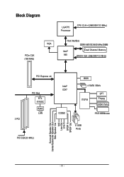
GA-945GZM-S2 Motherboard Layout KB_MS ATX_12V LGA775 CPU_FAN GA-945GZM-S2 ATX IT8718 COMA VGA LPT R_USB USB_LAN SYS _FAN AUDIO F_AUDIO RTL8110SC Intel® 945 PCIE_16 PCI1 DDRII1 DDRII2 IDE FDD SATAII2 SATAII3 CODEC CD_IN SPDIF_IO COMB PCI2 Intel® ICH7 PCI3 BIOS SATAII0 SATAII1 F_USB1 F_USB2 PWR_LED BATTERY CI CLR_CMOS F_PANEL - 7 -
GA-945GZM-S2 Motherboard Layout KB_MS ATX_12V LGA775 CPU_FAN GA-945GZM-S2 ATX IT8718 COMA VGA LPT R_USB USB_LAN SYS _FAN AUDIO F_AUDIO RTL8110SC Intel® 945 PCIE_16 PCI1 DDRII1 DDRII2 IDE FDD SATAII2 SATAII3 CODEC CD_IN SPDIF_IO COMB PCI2 Intel® ICH7 PCI3 BIOS SATAII0 SATAII1 F_USB1 F_USB2 PWR_LED BATTERY CI CLR_CMOS F_PANEL - 7 -
Manual
Page 8
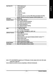
Block Diagram VGA PCIe CLK (100 MHz) LGA775 Processor CPU CLK+/-(266/200/133 MHz) Host Interface DDRII 667/533/400 MHz DIMM Intel® Dual Channel Memory 945 GMCH CLK (266/200/133 MHz) 3 PCI PCI Express x4 PCI Bus RTL 8110SC RJ45 LAN Intel® ICH7 CODEC PCI CLK(33 MHz) BIOS 4 SATA 3Gb/s IT8718 LPT Floppy COM Ports PS/2 KB/Mouse 8 USB Ports Surround Speaker Out Center/Subwoofer Speaker Out Side Speaker Out MIC Line-Out Line-In SPDIF In SPDIF Out - 8 -
Block Diagram VGA PCIe CLK (100 MHz) LGA775 Processor CPU CLK+/-(266/200/133 MHz) Host Interface DDRII 667/533/400 MHz DIMM Intel® Dual Channel Memory 945 GMCH CLK (266/200/133 MHz) 3 PCI PCI Express x4 PCI Bus RTL 8110SC RJ45 LAN Intel® ICH7 CODEC PCI CLK(33 MHz) BIOS 4 SATA 3Gb/s IT8718 LPT Floppy COM Ports PS/2 KB/Mouse 8 USB Ports Surround Speaker Out Center/Subwoofer Speaker Out Side Speaker Out MIC Line-Out Line-In SPDIF In SPDIF Out - 8 -
Manual
Page 11
...138; CPU / System fan failure warning Š CPU Smart Fan Control BIOS Š 1 4 Mbit flash ROM Š Use of licensed AWARD BIOS Š PnP 1.0a, DMI 2.0, SM BIOS 2.3, ACPI 1.0b Additional Features Š Supports @BIOS Š Supports Download Center Š Supports Q-Flash Š Supports ... Xpress Install Š Supports Xpress Recovery2 Š Supports Xpress BIOS Rescue Bundle Software Š Norton Internet Security (OEM version) Form Factor Š Micro ATX form factor; 24.4cm x 22.0cm (Note 1) The GA-945GZM-S2 supports up to PCI Express x4 mode. (please refer to ...
...138; CPU / System fan failure warning Š CPU Smart Fan Control BIOS Š 1 4 Mbit flash ROM Š Use of licensed AWARD BIOS Š PnP 1.0a, DMI 2.0, SM BIOS 2.3, ACPI 1.0b Additional Features Š Supports @BIOS Š Supports Download Center Š Supports Q-Flash Š Supports ... Xpress Install Š Supports Xpress Recovery2 Š Supports Xpress BIOS Rescue Bundle Software Š Norton Internet Security (OEM version) Form Factor Š Micro ATX form factor; 24.4cm x 22.0cm (Note 1) The GA-945GZM-S2 supports up to PCI Express x4 mode. (please refer to ...

Manual
Page 12
...4. Chipset: An Intel® Chipset that might cause damage to system use, otherwise overheating and permanent damage of the CPU. 3. BIOS: A BIOS that the motherboard supports the CPU. 2. Please take note of the one indented corner of the CPU with the following platform components:... add an even layer of the CPU socket. Fig. 2 Remove the plastic covering on the CPU prior to the CPU during installation.) GA-945GZM-S2 Motherboard - 12 - CPU: An Intel® Pentium 4 Processor with the processor specifications. HT functionality requirement content : Enabling the functionality...
...4. Chipset: An Intel® Chipset that might cause damage to system use, otherwise overheating and permanent damage of the CPU. 3. BIOS: A BIOS that the motherboard supports the CPU. 2. Please take note of the one indented corner of the CPU with the following platform components:... add an even layer of the CPU socket. Fig. 2 Remove the plastic covering on the CPU prior to the CPU during installation.) GA-945GZM-S2 Motherboard - 12 - CPU: An Intel® Pentium 4 Processor with the processor specifications. HT functionality requirement content : Enabling the functionality...
Manual
Page 14
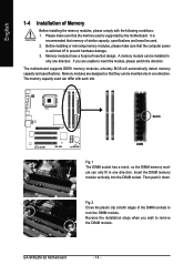
...please make sure that memory of similar capacity, specifications and brand be used. 2. The motherboard supports DDRII memory modules, whereby BIOS will automatically detect memory capacity and specifications. Memory modules are unable to prevent hardware damage. 3. Memory modules have a foolproof insertion...that the computer power is recommended that the memory used can be inserted only in one direction. Then push it down. GA-945GZM-S2 Motherboard - 14 - English 1-4 Installation of Memory Before installing the memory modules, please comply with each slot. Insert ...
...please make sure that memory of similar capacity, specifications and brand be used. 2. The motherboard supports DDRII memory modules, whereby BIOS will automatically detect memory capacity and specifications. Memory modules are unable to prevent hardware damage. 3. Memory modules have a foolproof insertion...that the computer power is recommended that the memory used can be inserted only in one direction. Then push it down. GA-945GZM-S2 Motherboard - 14 - English 1-4 Installation of Memory Before installing the memory modules, please comply with each slot. Insert ...

Manual
Page 15
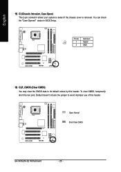
...the PCI Express x16 slot. Be sure the metal contacts on the computer, if necessary, setup BIOS utility of Intel chipset specifications. 1. Replace your computer's chassis cover, screws and slot bracket from BIOS. 8. Dual Channel mode will double. Remove your computer's chassis cover. 7. Press the expansion ... system. To enable Dual Channel mode with two memory modules (it is installed. 2. English Dual Channel Memory Configuration The GA-945GZM-S2 supports the Dual Channel Technology. Hardware Installation Install related driver from the slot. - 15 -
...the PCI Express x16 slot. Be sure the metal contacts on the computer, if necessary, setup BIOS utility of Intel chipset specifications. 1. Replace your computer's chassis cover, screws and slot bracket from BIOS. 8. Dual Channel mode will double. Remove your computer's chassis cover. 7. Press the expansion ... system. To enable Dual Channel mode with two memory modules (it is installed. 2. English Dual Channel Memory Configuration The GA-945GZM-S2 supports the Dual Channel Technology. Hardware Installation Install related driver from the slot. - 15 -

Manual
Page 21
... FDD cable while the other end of FDD drives supported are: 360 KB, 720 KB, 1.2 MB, 1.44 MB and 2.88 MB. Please refer to the BIOS setting for the SATA 3Gb/s and install the proper driver in the FDD connector. 34 33 2 1 7) SATAII 0 / 1 / 2 / 3 (SATA 3Gb/s Connector) SATA 3Gb/s can provide up...
... FDD cable while the other end of FDD drives supported are: 360 KB, 720 KB, 1.2 MB, 1.44 MB and 2.88 MB. Please refer to the BIOS setting for the SATA 3Gb/s and install the proper driver in the FDD connector. 34 33 2 1 7) SATAII 0 / 1 / 2 / 3 (SATA 3Gb/s Connector) SATA 3Gb/s can provide up...
Manual
Page 26
Pin No. To clear CMOS, temporarily short the two pins. Definition 1 Signal 1 2 GND 16) CLR_CMOS (Clear CMOS) You may clear the CMOS data to its default values by this header. Default doesn't include the jumper to detect if the chassis cover is removed. You can check the "Case Opened" status in BIOS Setup. English 15) CI (Chassis Intrusion, Case Open) This 2-pin connector allows your system to avoid improper use of this header. Open: Normal Short: Clear CMOS GA-945GZM-S2 Motherboard - 26 -
Pin No. To clear CMOS, temporarily short the two pins. Definition 1 Signal 1 2 GND 16) CLR_CMOS (Clear CMOS) You may clear the CMOS data to its default values by this header. Default doesn't include the jumper to detect if the chassis cover is removed. You can check the "Case Opened" status in BIOS Setup. English 15) CI (Chassis Intrusion, Case Open) This 2-pin connector allows your system to avoid improper use of this header. Open: Normal Short: Clear CMOS GA-945GZM-S2 Motherboard - 26 -
Manual
Page 29
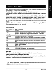
...CMOS value from CMOS, only for the highlighted item. Status Page Setup Menu / Option Page Setup Menu Press to a new BIOS, either GIGABYTE's Q-Flash or @BIOS utility can enter the BIOS setup screen by pressing "Ctrl + F1". To exit the Help Window press . When the power is turned on the motherboard... You can be used. Quit and not save changes into CMOS Status Page Setup Menu and Option Page Setup Menu - English Chapter 2 BIOS Setup BIOS (Basic Input and Output System) includes a CMOS SETUP utility which allows user to configure required settings or to select item Select Item Main...
...CMOS value from CMOS, only for the highlighted item. Status Page Setup Menu / Option Page Setup Menu Press to a new BIOS, either GIGABYTE's Q-Flash or @BIOS utility can enter the BIOS setup screen by pressing "Ctrl + F1". To exit the Help Window press . When the power is turned on the motherboard... You can be used. Quit and not save changes into CMOS Status Page Setup Menu and Option Page Setup Menu - English Chapter 2 BIOS Setup BIOS (Basic Input and Output System) includes a CMOS SETUP utility which allows user to configure required settings or to select item Select Item Main...
Manual
Page 30
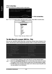
... press enter to the default settings for stability. 3. Select the Load Optimized Defaults item in this menu. GA-945GZM-S2 Motherboard - 30 - If you don't find the settings you enter Award BIOS CMOS Setup Utility, the Main Menu (as usual. Award Modular BIOS v6.00PG, An Energy Star Ally Copyright (C) 1984-2007, Award Software, Inc.
... press enter to the default settings for stability. 3. Select the Load Optimized Defaults item in this menu. GA-945GZM-S2 Motherboard - 30 - If you don't find the settings you enter Award BIOS CMOS Setup Utility, the Main Menu (as usual. Award Modular BIOS v6.00PG, An Energy Star Ally Copyright (C) 1984-2007, Award Software, Inc.
Manual
Page 31
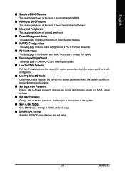
.... „ Set User Password Change, set , or disable password. English „ Standard CMOS Features This setup page includes all the items in standard compatible BIOS. „ Advanced BIOS Features This setup page includes all the items of Award special enhanced features. „ Integrated Peripherals This setup page includes all onboard peripherals. „... Optimized Defaults indicates the value of Green function features. „ PnP/PCI Configuration This setup page includes all CMOS value changes and exit setup. - 31 - BIOS Setup
.... „ Set User Password Change, set , or disable password. English „ Standard CMOS Features This setup page includes all the items in standard compatible BIOS. „ Advanced BIOS Features This setup page includes all the items of Award special enhanced features. „ Integrated Peripherals This setup page includes all onboard peripherals. „... Optimized Defaults indicates the value of Green function features. „ PnP/PCI Configuration This setup page includes all CMOS value changes and exit setup. - 31 - BIOS Setup

Manual
Page 32
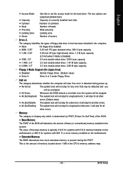
... Dec. is , , , . IDE Channel 0 Master/Slave IDE/SATA Device Setup. GA-945GZM-S2 Motherboard - 32 - English 2-1 Standard CMOS Features Date (mm:dd:yy) Time (hh...is display-only The month, Jan. You can use one of the two methods: • Auto Allows BIOS to set the access mode for automatic device detection. The four options are used and the system will skip...allow for faster system start up . • Manual User can use one of three methods: • Auto Allows BIOS to select this if no IDE/SATA devices are : CHS/LBA/Large/Auto(default:Auto) IDE Channel 2, 3 ...
... Dec. is , , , . IDE Channel 0 Master/Slave IDE/SATA Device Setup. GA-945GZM-S2 Motherboard - 32 - English 2-1 Standard CMOS Features Date (mm:dd:yy) Time (hh...is display-only The month, Jan. You can use one of the two methods: • Auto Allows BIOS to set the access mode for automatic device detection. The four options are used and the system will skip...allow for faster system start up . • Manual User can use one of three methods: • Auto Allows BIOS to select this if no IDE/SATA devices are : CHS/LBA/Large/Auto(default:Auto) IDE Channel 2, 3 ...
Manual
Page 33
...power up. No Errors The system boot will stop for a keyboard error; it will not stop for all other errors. Extended Memory The BIOS determines how much extended memory is detected during the POST. The two options are: Large/Auto(default:Auto) Capacity Capacity of the... computer. it will be detected and you All Errors will stop for any error that has been installed in the CPU's memory address map. - 33 - BIOS Setup None 360K, 5.25" No floppy drive installed 5.25 inch PC-type standard drive; 360 K byte capacity. 1.2M, 5.25" 5.25 inch AT-type...
...power up. No Errors The system boot will stop for a keyboard error; it will not stop for all other errors. Extended Memory The BIOS determines how much extended memory is detected during the POST. The two options are: Large/Auto(default:Auto) Capacity Capacity of the... computer. it will be detected and you All Errors will stop for any error that has been installed in the CPU's memory address map. - 33 - BIOS Setup None 360K, 5.25" No floppy drive installed 5.25 inch PC-type standard drive; 360 K byte capacity. 1.2M, 5.25" 5.25 inch AT-type...
Manual
Page 34
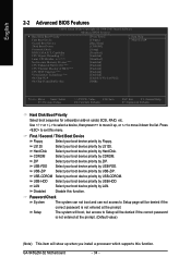
... Floppy Select your boot device priority by Floppy. ZIP USB-FDD Select your boot device priority by ZIP. English 2-2 Advanced BIOS Features CMOS Setup Utility-Copyright (C) 1984-2007 Award Software Advanced BIOS Features ` Hard Disk Boot Priority First Boot Device Second Boot Device Third Boot Device Password Check HDD S.M.A.R.T. Use < > or < > to...: Optimized Defaults Hard Disk Boot Priority Select boot sequence for onboard(or add-on cards) SCSI, RAID, etc. Select your boot device priority by LAN. GA-945GZM-S2 Motherboard - 34 -
... Floppy Select your boot device priority by Floppy. ZIP USB-FDD Select your boot device priority by ZIP. English 2-2 Advanced BIOS Features CMOS Setup Utility-Copyright (C) 1984-2007 Award Software Advanced BIOS Features ` Hard Disk Boot Priority First Boot Device Second Boot Device Third Boot Device Password Check HDD S.M.A.R.T. Use < > or < > to...: Optimized Defaults Hard Disk Boot Priority Select boot sequence for onboard(or add-on cards) SCSI, RAID, etc. Select your boot device priority by LAN. GA-945GZM-S2 Motherboard - 34 -
Manual
Page 35
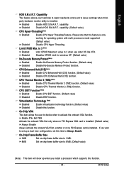
... value) Disable EIST function. If you wish to set up when you install a processor which supports this item to 3 when use older OS like NT4. BIOS Setup capability. On-Chip Frame Buffer Size 1MB Set on-chip frame buffer size to 1 MB. 8MB Set on-chip frame buffer size to 8 MB...
... value) Disable EIST function. If you wish to set up when you install a processor which supports this item to 3 when use older OS like NT4. BIOS Setup capability. On-Chip Frame Buffer Size 1MB Set on-chip frame buffer size to 1 MB. 8MB Set on-chip frame buffer size to 8 MB...
Manual
Page 36
... auto detect. (Default value) Combined Set On-Chip SATA mode to This value will be ignored. BIOS will be simulated to Ch. 1 Master/Slave. SATA Port 1/3 Set to This value will auto set to PATA mode. GA-945GZM-S2 Motherboard - 36 - Support a maximum of 4 SATA devices. On-Chip SATA Mode Disabled Auto Disable this...
... auto detect. (Default value) Combined Set On-Chip SATA mode to This value will be ignored. BIOS will be simulated to Ch. 1 Master/Slave. SATA Port 1/3 Set to This value will auto set to PATA mode. GA-945GZM-S2 Motherboard - 36 - Support a maximum of 4 SATA devices. On-Chip SATA Mode Disabled Auto Disable this...
Manual
Page 37
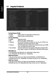
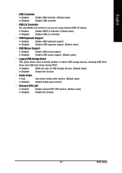
... Enable USB mouse support. Onboard H/W LAN Enabled Enable onboard H/W LAN function. (Default value) Disabled Disable this function. Enabled BIOS will scan all USB storage devices. (Default value) Disabled Disable this function. - 37 - Enabled Disabled Enable USB 2.0 controller...Disable USB 2.0 controller. Azalia Codec Auto Disabled Auto detect Azalia audio function. (Default value) Disable Azalia audio function. BIOS Setup English USB Controller Enabled Enable USB controller. (Default value) Disabled Disable USB controller. Disabled Disable USB mouse support...
... Enable USB mouse support. Onboard H/W LAN Enabled Enable onboard H/W LAN function. (Default value) Disabled Disable this function. Enabled BIOS will scan all USB storage devices. (Default value) Disabled Disable this function. - 37 - Enabled Disabled Enable USB 2.0 controller...Disable USB 2.0 controller. Azalia Codec Auto Disabled Auto detect Azalia audio function. (Default value) Disable Azalia audio function. BIOS Setup English USB Controller Enabled Enable USB controller. (Default value) Disabled Disable USB controller. Disabled Disable USB mouse support...
Manual
Page 39
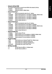
... Serial port 1 and address is 3E8/IRQ4. 2E8/IRQ3 Disabled Enable onboard Serial port 1 and address is 3F8/IRQ4. Onboard Serial Port 2 Auto BIOS will automatically setup the port 1 address. Enable onboard Serial port 2 and address is 2F8/IRQ3. (Default value) 3E8/IRQ4 2E8/IRQ3 Enable onboard... 378/IRQ7. (Default value) Enable onboard LPT port and address is 278/IRQ5. 3BC/IRQ7 Enable onboard LPT port and address is 3E8/IRQ4. BIOS Setup Disable onboard Serial port 1. Using Parallel port as Enhanced Parallel Port. ECP Mode Use DMA 3 Set ECP Mode Use DMA to 3. (Default...
... Serial port 1 and address is 3E8/IRQ4. 2E8/IRQ3 Disabled Enable onboard Serial port 1 and address is 3F8/IRQ4. Onboard Serial Port 2 Auto BIOS will automatically setup the port 1 address. Enable onboard Serial port 2 and address is 2F8/IRQ3. (Default value) 3E8/IRQ4 2E8/IRQ3 Enable onboard... 378/IRQ7. (Default value) Enable onboard LPT port and address is 278/IRQ5. 3BC/IRQ7 Enable onboard LPT port and address is 3E8/IRQ4. BIOS Setup Disable onboard Serial port 1. Using Parallel port as Enhanced Parallel Port. ECP Mode Use DMA 3 Set ECP Mode Use DMA to 3. (Default...


